Table of Contents
Advertisement
Quick Links
One Technology Way • P.O. Box 9106 • Norwood, MA 02062-9106, U.S.A. • Tel: 781.329.4700 • Fax: 781.461.3113 •
Evaluating the
FEATURES
4 analog inputs
8 analog outputs
Stereo S/PDIF input and output
Self boot EEPROM
Headers for interfacing to off board peripherals
EVALUATION KIT CONTENTS
EVAL-ADAU1467Z evaluation board
EVAL-ADUSB2EBZ
(USBi) communications adapter
USB cable with Mini-B plug
6 V ac to dc power supply
HARDWARE REQUIRED
PC running Windows XP, Windows Vista, or Windows 7
Analog, stereo audio source with an output cable terminated
with a 3.5 mm (1/8 inch) plug (for the analog input)
Headphones, desktop speakers, or audio input with a cable
terminated with a 3.5 mm (1/8 inch) plug (for the analog
output)
S/PDIF audio source and receiver, each with optical cables
terminated with TOSLINK connectors (for digital
input/output)
SOFTWARE REQUIRED
SigmaStudio
software, available for download from the
SigmaStudio
product page
DOCUMENTS NEEDED
ADAU1467
data sheet
AD1937
data sheet
Mic Canvas user guide
AN-1006 Application Note
PLEASE SEE THE LAST PAGE FOR AN IMPORTANT
WARNING AND LEGAL TERMS AND CONDITIONS.
www.analog.com
ADAU1463
and
ADAU1467 SigmaDSP
Rev. A (Draft) | Page 1 of 55
EVAL-ADAU1467Z
Audio Processors
GENERAL DESCRIPTION
This user guide details the design, setup, and operation of the
EVAL-ADAU1467Z evaluation board. This board is suitable for
the evaluation of, and software development for, the
and
ADAU1463
SigmaDSP® processors. Note that the
and the
ADAU1463
are functionally identical; however, the
ADAU1467
has more program and data memory than the
ADAU1463. When using this evaluation board to evaluate the
ADAU1463, select the
ADAU1463
section) rather than the ADAU1467, as shown in Figure 11.
Performing this action informs the compiler to limit the amount of
memory allocated to match the ADAU1463. All other procedures
and instructions in this user guide are identical for the
ADAU1463
and ADAU1467.
This evaluation board provides access to the digital serial audio
ports of the ADAU1467. Four analog inputs and eight analog
outputs are provided by the
evaluation kit. Switches enable the evaluation of alternate
features provided by many of the pins with multiplexed
functionality, and numerous headers provide access to serial
audio ports and the master and slave control ports. These
selectable modes and headers make the EVAL-ADAU1467Z
well suited to prototyping larger application circuits, as well as
initial device evaluation. The
using Analog Devices, Inc., SigmaStudio® software, which
interfaces to the evaluation board via a USB interface (USBi).
The on-board, electronically erasable programmable read only
memory (EEPROM) can be programmed for self boot mode.
The evaluation board is powered by a 6 V dc supply, which is
regulated to the voltages required on the board. The printed
circuit board (PCB) is a 4-layer design with a ground plane and a
power plane on the inner layers. The evaluation board includes
connectors for external analog inputs and outputs and optical
Sony/Philips Digital Interface (S/PDIF) interfaces. The master
clock is provided by the integrated oscillator circuit and the on-
board 12.288 MHz passive crystal.
For full details, see the
ADAU1467
which must be used in conjunction with this user guide when
using the evaluation board.
UG-1134
ADAU1467
ADAU1467
block (see the
SigmaStudio
AD1937
codec included in the
ADAU1467
core is programmed
and
AD1937
data sheets,
Advertisement
Table of Contents

Related Manuals for Analog Devices SigmaDSP ADAU1463


Summary of Contents for Analog Devices SigmaDSP ADAU1463
-
Page 1: Features
The ADAU1467 core is programmed SigmaStudio software, available for download from the using Analog Devices, Inc., SigmaStudio® software, which SigmaStudio product page interfaces to the evaluation board via a USB interface (USBi). The on-board, electronically erasable programmable read only DOCUMENTS NEEDED memory (EEPROM) can be programmed for self boot mode. -
Page 2: Table Of Contents
UG-1134 EVAL-ADAU1467Z TABLE OF CONTENTS Features ....................1 AD1937 Codec ................14 Evaluation Kit Contents ..............1 Serial Audio Data Input and Output ........17 Hardware Required ................1 Multipurpose Pins (MPx) ............17 Software Required ................1 Status LEDs ................. 18 Documents Needed ................ -
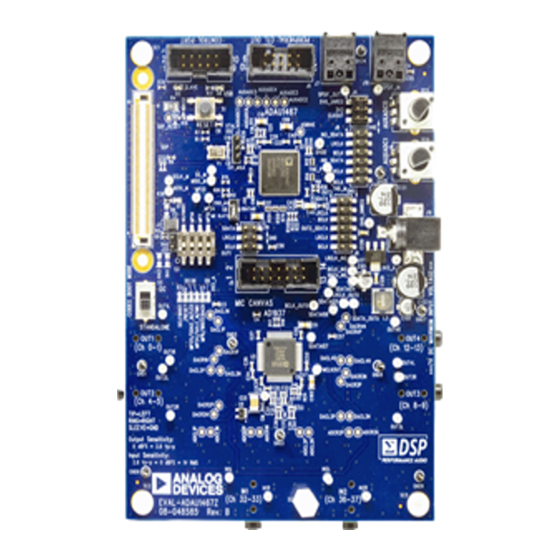
Page 3: Eval-Adau1467Z Evaluation Board Photograph
EVAL-ADAU1467Z UG-1134 EVAL-ADAU1467Z EVALUATION BOARD PHOTOGRAPH Figure 1. Rev. A (Draft) | Page 3 of 55... -
Page 4: Setting Up The Evaluation Board
A full version of SigmaStudio, which includes a library of DSP building blocks and the required USBi drivers, is available for download from the SigmaStudio software page on the Analog Devices website at www.analog.com/SigmaStudio. INSTALLING THE SigmaStudio... -
Page 5: Powering Up The Evaluation Board
EVAL-ADAU1467Z UG-1134 POWERING UP THE EVALUATION BOARD Power is supplied to the evaluation board using a dc power supply with a female positive center plug. The plug has a 2.1 mm inner diameter, a 5.5 mm outer diameter, and a 9.5 mm length (see Figure 4). -
Page 6: Connecting The Audio Cables
UG-1134 EVAL-ADAU1467Z CONNECTING THE AUDIO CABLES To connect the audio cables to the evaluation board, take the following steps: Connect a stereo audio source to J14 (IN1) with a standard 3.5 mm (1/8 inch) stereo tip, ring, sleeve (TRS) audio cable. The audio signals must be single-ended and line level, with a maximum voltage of 2.8 V p-p (1.0 V ). - Page 7 EVAL-ADAU1467Z UG-1134 OUT1 Figure 9. Location of Stereo Output OUT1 (J12) and Stereo Input IN1 (J14) Rev. A (Draft) | Page 7 of 55...
-
Page 8: Setting Up Communications In Sigmastudio
UG-1134 EVAL-ADAU1467Z SETTING UP COMMUNICATIONS IN SigmaStudio To set up communications in SigmaStudio, take the following steps: Start the SigmaStudio software by double clicking the shortcut on the desktop or by finding and executing the executable file in Windows Explorer. To create a new project, select New Project from the File menu or press CTRL + N. -
Page 9: Creating A Basic Signal Flow
EVAL-ADAU1467Z UG-1134 CREATING A BASIC SIGNAL FLOW To create a signal processing flow, take the following steps: Click the Schematic tab near the top of the window (see Figure 15). Figure 15. Schematic Tab Figure 17. Input Block To add the appropriate elements to the project space, click Add two Output blocks as follows, ensuring that these and drag the elements from the Tree ToolBox on the left of blocks are assigned to Channel 0 and Channel 1:... - Page 10 UG-1134 EVAL-ADAU1467Z Figure 22. Growing the Volume Control to Two Channels Figure 20. Connected Signal Flow with Stereo Input and Stereo Output Connect the blocks as shown in Figure 23. The default register settings in SigmaStudio are configured to match the hardware of the EVAL-ADAU1467Z, including the signal routing between the ADAU1467 and the...
-
Page 11: Downloading The Program To The Dsp
EVAL-ADAU1467Z UG-1134 DOWNLOADING THE PROGRAM TO THE DSP To compile and download the code to the digital signal processor (DSP), click the Link/Compile/Download button in the main toolbar of SigmaStudio (see Figure 24). Alternatively, press F7. Figure 24. Link/Compile/Download Button After the code downloads to the DSP, the following events occur in order: If the compiler completes compiling the project, the... - Page 12 UG-1134 EVAL-ADAU1467Z Figure 29. Adding a Channel to the Filter Connect the filter in series between the Input block and the Single Volume blocks so that the filter can be applied to the signals passing through the DSP. The completed signal flow resembles Figure 30.
- Page 13 EVAL-ADAU1467Z UG-1134 Click the Probe button on the Probe block to open the simulation window. Click the Stimulus button on the Stimulus block to begin the simulation. Move the slider on the Medium-Size Eq block to control the filter gain. Click on the blue icon at the top of the filter block to change other parameters of the filter.
-
Page 14: Evaluation Board Features
UG-1134 EVAL-ADAU1467Z EVALUATION BOARD FEATURES The EVAL-ADAU1467Z provides access to the master and slave To generate a reset in software, right click in the empty white control ports, multipurpose pins, auxiliary ADCs, S/PDIF border of the USB Interface block in the Hardware Configuration interfaces, and serial ports of the ADAU1467 as well as the... - Page 15 EVAL-ADAU1467Z UG-1134 The signals pass through the AD1937 ADCs and then are sent section for the configuration of the to the ADAU1467 serial input ports in I S format. The mapping SDATAIOx pins. of input signals to input channels in SigmaDSP SigmaStudio is shown in Table 1.
- Page 16 UG-1134 EVAL-ADAU1467Z AD1937 CODEC ADAU1467 DAC FRAME SYNC LRCLK_OUT0 DAC BIT CLOCK BCLK_OUT0 ANALOG OUT OUTPUT CHANNELS 0-1 SDATA_OUT0 8-CHANNEL OUTPUT CHANNELS 4-5 SDATAIO5 (4 × I 2 S) OUTPUT CHANNELS 8-9 SDATAIO6 OUTPUT CHANNELS 12-13 SDATAIO7 ADC FRAME SYNC LRCLK_IN2 ANALOG IN ADC BIT CLOCK...
-
Page 17: Serial Audio Data Input And Output
EVAL-ADAU1467Z UG-1134 SERIAL AUDIO DATA INPUT AND OUTPUT Figure 42. Power and CLKOUT Header, J8 Input Serial Port 0 and Input Serial Port 3 are available on Header J8. Output Serial Port 2 and Output Serial Port 3 are available on Header J9. These headers are standard, two column headers with 0.1 inch (2.54 mm) spacing. -
Page 18: Status Leds
UG-1134 EVAL-ADAU1467Z To configure the operation of the multipurpose pins, navigate to the MULTIPURPOSE tab in the Hardware Configuration tab SigmaStudio (see Figure 45). Figure 45. Multipurpose Pin Configuration in SigmaStudio Figure 46. Multipurpose Pin Function Selection Switch, S8 Figure 44. Self Boot Slide Switch, S3 Table 3. -
Page 19: Auxiliary Adc Pins
EVAL-ADAU1467Z UG-1134 and physical way to control parameters such as gain, filter corner frequency, slew rate, and compression level. Figure 47. Status LEDs AUXILIARY ADC PINS ADAU1467 has a 10-bit, successive approximation Figure 49. Potentiometers Connected to AUXADC0 and AUXADC1 register (SAR) ADC multiplexed across six input channels. - Page 20 UG-1134 EVAL-ADAU1467Z Setting Up Communications in SigmaStudio section. The arithmetic shift block performs a bitwise right shift Add an input and two output blocks as described in the or left shift. Click the blue button to select the direction. Creating a Basic Signal Flow section. Ensure the block is performing a left shift.
- Page 21 EVAL-ADAU1467Z UG-1134 Wire the blocks together as shown in Figure 56. Note that the position of blocks in the diagram does not matter. Click the Link/Compile/Download button (see Figure 24) or press F7 to compile the signal flow and download it to the hardware.
-
Page 22: S/Pdif Input And Output
UG-1134 EVAL-ADAU1467Z Figure 56. Completed Signal Flow with DSP Readback S/PDIF INPUT AND OUTPUT S/PDIF OUT S/PDIF IN The EVAL-ADAU1467Z evaluation board has two optical S/PDIF interfaces. One interface is an input that converts the optical signal to an electrical signal, which is sent to the ADAU1467 S/PDIF receiver (the SPDIFIN pin). - Page 23 EVAL-ADAU1467Z UG-1134 ADAU1467 S/PDIF receiver accepts signals with sample To access the SPDIF tab, click the right arrow to scroll rates between 18 kHz and 192 kHz. Because the incoming signal (see Figure 61).Then, click the SPDIF tab (see Figure 62). is asynchronous to the system sample rate, an asynchronous There are several register control tabs listed across the sample rate converter (ASRC) must be used to convert the...
- Page 24 UG-1134 EVAL-ADAU1467Z Click the ROUTING_MATRIX tab (see Figure 66) to From the dropdown menu that appears, select From allow the configuration of the routing matrix. DSP to choose the signal coming from the DSP core (see Figure 70). Figure 66. Selecting the ROUTING_MATRIX Tab To configure the S/PDIF receiver signal routing, click the first asynchronous sample rate converter, ASRC 0 (see Figure 67) and configure ASRC 0 using the dropdown menus...
- Page 25 EVAL-ADAU1467Z UG-1134 Add two S/PDIF outputs to the project as follows: From the IO > SPDIF > Output folder, click Spdif Output (see Figure 74) and drag it into the project space to the right of the toolbox. Figure 74. S/PDIF Output Block Selection Repeat the previous step to add another Spdif Output block.
-
Page 26: Self Boot
UG-1134 EVAL-ADAU1467Z SELF BOOT A 1 Mb, 20 MHz, SPI, serial EEPROM memory is included on the EVAL-ADAU1467Z evaluation board. The ADAU1467 capable of booting and executing a program without help from an external microcontroller. This feature allows any project developed within SigmaStudio to execute when the... - Page 27 EVAL-ADAU1467Z UG-1134 Figure 79. Writing to the EEPROM Through the ADAU1467 Master SPI Port Figure 80. External Memory Erase and Overwrite Warning Window An EEPROM Properties dialog box appears. Enter the appropriate values into the text fields as shown in Figure 81, then click OK.
-
Page 28: Slave Control Port
UG-1134 EVAL-ADAU1467Z To execute a self boot operation, take the following steps: Set the self boot switch (S2) to enabled. Press and release the RESET push-button (S1). A self boot operation is then performed, and the ADAU1467 runs the program stored in the EEPROM. SLAVE CONTROL PORT The Control Port header (J1) is a 10-pin header designed to work with the... -
Page 29: Evaluation Board Hardware
EVAL-ADAU1467Z UG-1134 EVALUATION BOARD HARDWARE IC DESCRIPTIONS Table 5. IC Descriptions Reference Functional Name Description Clock buffer, 1:9 Buffers the master clock signal (MCLK) for distribution to multiple ICs and to headers. ADAU1467 SigmaDSP audio processor Acts as an audio hub for all audio inputs and outputs in the system and performs digital signal processing on those signals. -
Page 30: Evaluation Board Schematics And Artwork
UG-1134 EVAL-ADAU1467Z EVALUATION BOARD SCHEMATICS AND ARTWORK From Mic From From ADCs From SDP Header J8 (CODEC) Canvas Connector Switch S8 Connector (& Header J8) Figure 83. SigmaDSP Audio Processor Schematic Rev. A (Draft) | Page 30 of 55... - Page 31 EVAL-ADAU1467Z UG-1134 Analog Audio Outputs Figure 84. CODEC Schematic Rev. A (Draft) | Page 31 of 55...
- Page 32 UG-1134 EVAL-ADAU1467Z IOVDD AUXADC0 10k0 LINEAR AUXADC1 10k0 LINEAR Figure 85. AUXADCx Potentiometer Schematic IOVDD 2k43 2k43 2k43 MP24 47k0 MC_LED_BLANK MP25 SDATAIO0: MC_XLAT MC_XLAT SDATAIO0 MP6:SS2_M SS2_M Figure 86. Pull-Up Resistors and Configuration Option Switch Schematic 5V00_UNREG ADA4610-1 CM_BIAS U4-A AMP_REF 47.0uF...
- Page 33 EVAL-ADAU1467Z UG-1134 IN1R R101 R100 10µF 4k99 4k99 330pF ADCR1N U12-A 10µF 49R9 – ADCR1N ANALOG INPUT 1 R102 ADA4841-2YRMZ 100pF CHANNELS 32 TO 33 100pF 100k ADCR1P 10µF 4k99 4k99 49R9 ADCR1P RING U12-B – 100R 1.0nF 1.0nF AMP_REF SLEEVE 0.10µF 330pF...
- Page 34 UG-1134 EVAL-ADAU1467Z C138 IN2R R145 R144 C126 10µF 4k99 4k99 330pF ADCR2N C124 R135 U16-A 10µF 49R9 – ADCR2N ANALOG INPUT 2 C127 R136 ADA4841-2YRMZ 100pF CHANNELS 36 TO 37 100pF 100k C121 ADCR2P R129 R123 10µF 4k99 4k99 49R9 ADCR2P RING U16-B...
- Page 35 EVAL-ADAU1467Z UG-1134 33pF 4k99 DACR2N OUT2R U9-B 10k0 10µF 49R9 DACR2N – ANALOG OUTPUT 2 DACR2P CHANNELS 4 TO 5 100k 82pF 10k0 ADA4841-2YRMZ DACR2P RING 4k99 AMP_REF 33pF SLEEVE 33pF 4k99 5V00_UNREG DACL2N OUT2L U9-A 10k0 10µF 49R9 DACL2N –...
- Page 36 UG-1134 EVAL-ADAU1467Z 33pF 4k99 DACR1N OUT4R U8-B 10k0 10µF 49R9 DACR1N – ANALOG OUTPUT 4 R140 DACR1P CHANNELS 12 TO 13 100k 82pF 10k0 ADA4841-2YRMZ DACR1P RING 4k99 AMP_REF 33pF SLEEVE C110 33pF R119 4K99 5V00_UNREG DACL4N OUT4L R116 C136 U13-A R138 10k0...
- Page 37 EVAL-ADAU1467Z UG-1134 MC_LED_BLANK IOVDD MC_MIC_POWER MC_XLAT BCLK_IN1 MC_TDM8_SDATAIO1_MP17 SDATA_IN1 LRCLK_IN1 MC_LED_SDATA_SDATAIO3_MP19 MC_LED_SCLK_SDATAIO2_MP18 Figure 96. Microphone Canvas Header Schematic IOVDD 0.10µF 0.10µF 0.10µF 0.10µF 0.10µF 0.10µF 0.10µF 0.10µF Figure 97. Plane Stitching Bypass Capacitor Schematic 5V0_UNREG 5V00_UNREG 3V3_A 3V3_A IOVDD ADP3338-3.3V C131 C130 C129...
- Page 38 UG-1134 EVAL-ADAU1467Z IOVDD I/O SUPPLY FOR TARGET SLAVE BOARD EI3 1A MASTER 0R00 OPEN 1206 USB 5V 5V00_UNREG CLKOUT2 DAU_MCLK OPEN USB 5V HIROSE_FX8-120P-SV1(91) 120 PIN_HEADER SPORT1_CLK BCLK_OUT1 SPORT1_D0 SDATA_IN0 SPORT1_FS LRCLK_OUT1 LRCLK_IN0 SPORT0_FS SPORT0_D0 SDATA_OUT1 BCLK_IN0 SPORT0_CLK SS_M MOSI_M MISO_M SCLK_M MP25...
- Page 39 EVAL-ADAU1467Z UG-1134 IOVDD I/O SUPPLY FROM MASTERBOARD EI3 1A SLAVE OPEN 0805 0805 OPEN USB 5V 33R2 5V00_UNREG SDP_MCLK_IN DAU_MCLK 0805 OPEN USB 5V 47µF HIROSE_FX8-120S-SV(21) 120PIN SOCKET SPORT1_CLK BCLK_IN0 SPORT1_D0 SDATA_OUT1 SDP_TDM8 SPORT1_D1 SPORT1_FS LRCLK_IN0 LRCLK_OUT1 SPORT0_D1 SPORT0_FS SDATA_IN0 SPORT0_D0 BCLK_OUT1 SPORT0_CLK...
- Page 40 UG-1134 EVAL-ADAU1467Z IOVDD 0.10µF SS_M MISO_M 10k0 SS_M MOSI_M SCLK_M MISO_M HOLD SCLK_M MOSI_M 25AA1024_1MBIT_SPI_EEPROM Figure 102. Self-Boot SPI Memory Schematic IOVDD MP15 MP14 SELFBOOT 4-POS DIP SWITCH 10k0 10k0 10k0 10k0 Figure 103. Self-Boot, MP15, MP7, and MP14 DIP Switch Schematic SDATA_IN3 SDATA_OUT3 LRCLK_IN3...
- Page 41 EVAL-ADAU1467Z UG-1134 IOVDD USB 5 VOLTS 10k0 MISO USB_RESET 1k00 SCLK MOSI HEADER_10WAY_POL CONNECTED Figure 105. Slave Control Port Input Header (USBi) Schematic IOVDD SPDIF_OUT SPDIF_IN C128 SPDIFOUT VOUT SPDIFIN 0.10µF 0.10µF Figure 106. TOSLINK Optical Input/Output Connector Schematic Rev. A (Draft) | Page 41 of 55...
- Page 42 UG-1134 EVAL-ADAU1467Z MC_MIC_POWER U7-B 475R INV_MIC_PWR U7-F 475R WRITEBACK IOVDD 0.10µF 475R 3V3_A U7-A IOVDD U7-D 475R SELFBOOT U7-C 475R RESET U7-E 475R USB_RESET 74ACT04SC_HEXINVERTER Figure 107. Status LEDs and Inverter Schematic 5V00_UNREG 100k RESET 0.10µF WRITEBACK ADM811MARTZ THRESHOLD VOLTAGE: 100k 4.38VDC Figure 108.
- Page 43 EVAL-ADAU1467Z UG-1134 Figure 109. EVAL-ADAU1467Z Layout, Top Assembly and Silkscreen Rev. A (Draft) | Page 43 of 55...
- Page 44 UG-1134 EVAL-ADAU1467Z Figure 110. EVAL-ADAU1467ZLayout, Top Copper Rev. A (Draft) | Page 44 of 55...
- Page 45 EVAL-ADAU1467Z UG-1134 Figure 111. EVAL-ADAU1467Z Layout, Layer 2 (Ground) Rev. A (Draft) | Page 45 of 55...
- Page 46 UG-1134 EVAL-ADAU1467Z Figure 112. EVAL-ADAU1467Z Layout, Layer 3 (Signal/Power) Rev. A (Draft) | Page 46 of 55...
- Page 47 EVAL-ADAU1467Z UG-1134 Figure 113. EVAL-ADAU1467Z Layout, Layer 4 (Power) Rev. A (Draft) | Page 47 of 55...
- Page 48 UG-1134 EVAL-ADAU1467Z Figure 114. EVAL-ADAU1467Z Layout, Layer 5 (Ground) Rev. A (Draft) | Page 48 of 55...
- Page 49 EVAL-ADAU1467Z UG-1134 Figure 115. EVAL-ADAU1467Z Layout, Bottom Copper Rev. A (Draft) | Page 49 of 55...
- Page 50 UG-1134 EVAL-ADAU1467Z Figure 116. EVAL-ADAU1467Z Layout, Bottom Assembly (Viewed from Above) Rev. A (Draft) | Page 50 of 55...
-
Page 51: Ordering Information
EVAL-ADAU1467Z UG-1134 ORDERING INFORMATION BILL OF MATERIALS Table 7. Reference Designator Description Manufacturer Part Number C1, C3 to C7, C9, C11, C12, Multilayer ceramic capacitors, 16 V, X7R Murata ENA GRM155R71C104KA88D C14, C17, C20, C22, C24, C26, (0402), 0.10 µF C27 to C29, C40, C41, C43, C45, C47, C50, C52, C55 to C60, C64, C65, C72, C75 to... - Page 52 UG-1134 EVAL-ADAU1467Z Reference Designator Description Manufacturer Part Number 3-position session initiation protocol (SIP) Sullins PBC03SAAN or cut header, 3-jumper PBC36SAAN 14-way shroud polarized header, 2 × 7 N2514-6002RB TOSLINK, 16 Mpbs, optical transmitter Everlight Americas PLT133/T10W 16-way unshrouded, 2 × 8 PBC08DAAN, or cut PBC36DAAN 14-way unshrouded header, 2 ×...
- Page 53 IC clock buffer 1:9, 16-lead SOIC On Semiconductor PCS2I2309NZG16SR SPI EEPROM, 128k × 8 (1 Mbit), 20 MHz Microchip 25AA1024-I/SM High accuracy, low dropout, 3.3 V dc voltage Analog Devices ADP3338AKCZ-3.3-R7 regulator 300 MHz, SigmaDSP Analog Devices ADAU1467WBCPZ 4 ADC/8 DAC with phase-locked loop (PLL),...
-
Page 54: Related Links
UG-1134 EVAL-ADAU1467Z Reference Designator Description Manufacturer Part Number C69, C70, C78, C85, C106 to Multilayer ceramic capacitors, 50 V, NP0 Murata ENA GRM1555C1H820JA01D C108, C123 (0402), 82 pF C8, C10 Multilayer ceramic capacitors, 50 V, NP0 Murata ENC GRM1555C1H220JA01D (0402), 22 pF C83, C84 Aluminum electrolytic capacitors, 105°C, Panasonic EC... - Page 55 (“Agreement”) unless you have purchased the Evaluation Board, in which case the Analog Devices Standard Terms and Conditions of Sale shall govern. Do not use the Evaluation Board until you have read and agreed to the Agreement. Your use of the Evaluation Board shall signify your acceptance of the Agreement. This Agreement is made by and between you (“Customer”) and Analog Devices, Inc.
Need help?
Do you have a question about the SigmaDSP ADAU1463 and is the answer not in the manual?
Questions and answers