Table of Contents
Advertisement
Quick Links
BPS-4H (High Temperature)
This manual contains information necessary for the safe and proper use of the BPS-4H. Included are specifications
for the standard configurations of the pump system and instructions regarding its use, installation, operation,
adjustment, inspection and maintenance. For special configurations of the pump system refer to accompanying
information. If the system must be configured for other parameter settings, then the Levitronix
according manual Levitronix
to ensure the safe and effective use of this product. After reading this manual, please store the manual where the
personnel responsible for operating the pump system can readily refer to it at any time.
PL-2009-03, Rev04, DCO# 21-101
3.2 bar
50 liters/min
USER MANUAL
Doc.# PL-4046-00) is necessary. Familiarize yourself with the contents of the manual
User Manual for BPS-4H (High Temp.)
(46.4 psi)
(13.2 gallons/min)
®
Service Software (with
www.levitronix.com
First Release: 21-May-2012
Last Update: 28-Apr-2021
Advertisement
Table of Contents

Related Manuals for Levitronix BPS-4H Series


Summary of Contents for Levitronix BPS-4H Series
- Page 1 For special configurations of the pump system refer to accompanying ® information. If the system must be configured for other parameter settings, then the Levitronix Service Software (with ...
-
Page 2: Table Of Contents
Mechanical Installation of Adaptor Cables....................27 OPERATION ................................28 Overview of Main Operation Modes ......................28 System Operation with the LUI-A Levitronix User Interface ..............28 System Operation with PLC-A PLC Interface-Module ................29 INSPECTION AND MAINTENANCE ......................... 31 Regular Check of Pump Head and Motor Screws ................... 31 Replacement Interval of the Impeller ...................... -
Page 3: Safety Precautions
User Manual for BPS-4H (High Temp.) www.levitronix.com 1 Safety Precautions CAUTION ® Do not under any circumstances open the controller or motor. Levitronix does not assume responsibility for any damage, which occurs under such circumstances. CAUTION High magnetic field strength of pump impeller. -
Page 4: Specifications
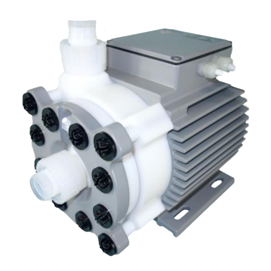
User Manual for BPS-4H (High Temp.) www.levitronix.com 2 Specifications 2.1 Specifications of Components Figure 1 shows the main system components (motor, controllers, and pump head) and Figure 2 illustrates the accessories. Figure 1: Pump system with standard components Figure 2: Pump system accessories... - Page 5 User Manual for BPS-4H (High Temp.) www.levitronix.com System Name Article # Pump Head Motor Controller Note BPS-4H.1 100-90688 BSM-4.10-05 Adaptor/Extension (0.5 - 10m) cables according to Table 3 have to CP-4.25 LC325P be ordered as separate article with specified length.
-
Page 6: Standard System Configurations
Figure 4. Levitronix provides either turnkey solutions for closed-loop flow control or helps to design your own flow control system. In addition to the flow control function, the Levitronix control firmware comes with several condition monitoring features to monitor the integrity of the fluid circuit. Levitronix flow control systems can generate alarms for preventive filter exchange, no-flow conditions or line clogging. -
Page 7: System Configuration For Pumping Acid/Gas Mixtures
) or SPM (H ) the risk of priming loss by bubble collection in the pump head can be addressed with the setup illustrated in Figure 5. ® Contact Levitronix for more information on this operation mode. Aspirator Air Out... -
Page 8: System Electronics
User Manual for BPS-4H (High Temp.) www.levitronix.com 2.4 System Electronics Figure 6: Block diagram and wiring pattern of the BPS-4 electronics for speed control - PLC configuration for standard firmware with speed control - For other configurations of PLC Inputs and Outputs refer to corresponding firmware documentation... -
Page 9: Flow/Pressure Curves
User Manual for BPS-4H (High Temp.) www.levitronix.com 2.5 Flow/Pressure Curves [gallons/min] 4500 rpm Specific gravity = 1.8 g/cm Viscosity = ~5 cP Liquid Temp.: 150 4200 rpm Liquid: Sulfuric Acid 96% 4000 rpm [bar] [psi] 3500 rpm 3000 rpm 2000 rpm [liters/min] Figure 7: Pressure/flow rate chart for sulfuric acid (96%) at 150°C... -
Page 10: Maximum Static Pressure For Pump Head
User Manual for BPS-4H (High Temp.) www.levitronix.com [gallons/min] Specific gravity = 1 g/cm Viscosity = 0.7 cP 6500 rpm Liquid Temp.: 40 C Liquid: H 6000 rpm 5500 rpm [psi] [bar] 5000 rpm 4000 rpm 3000 rpm [liters/min] Figure 9: Pressure/flow rate chart for water at 40°C (Typical curves measured with pump head CP-4.25.) -
Page 11: Basic Dimensions Of Main Components
User Manual for BPS-4H (High Temp.) www.levitronix.com 2.7 Basic Dimensions of Main Components Cooling Circuit INLET Pillar Super 300 ¼” Inlet/Outlet Fittings Pillar Super 300 1” Pump/Motor Screws Stainless Steel + PTFE 4 pcs. M8x30 mm Torque Spec.: 1.2 Nm Suction Port Pillar Super 300 ¼”... - Page 12 User Manual for BPS-4H (High Temp.) www.levitronix.com Pump head CP-4.36 is Inlet/Outlet Fittings without suction port. Pillar Super 300 1” Cooling Circuit INLET Suction Port Pillar Super 300 ¼” Pillar Super 300 ¼” Pump/Motor Screws: Stainless Steel 4 pcs. M8x80 mm Torque Spec.: 17 Nm...
- Page 13 User Manual for BPS-4H (High Temp.) www.levitronix.com Cable Cable OD Cable OD Minimum Bending Radius Minimum Bending Radius Jacket Motor Sensor Motor Power Permanent Installation Sometimes Moved 6.60 mm 8.40 mm 7x cable OD 15 x cable OD 7.20 mm 10.0 mm...
-
Page 14: Engineering Information
User Manual for BPS-4H (High Temp.) www.levitronix.com 3 Engineering Information 3.1 Sealing and Material Concept Figure 15: Sealing and material concept of the BSM-4.10 motor with CP-4.25 pump head Item System Materials Component Description Pump casing (lid and bottom) PTFE ... - Page 15 User Manual for BPS-4H (High Temp.) www.levitronix.com Figure 16: Sealing and material concept of the BSM-4.11 motor with CP-4.34/36 pump heads Item System Materials Component Description Pump casing (lid and bottom) PTFE Primary static seal of housing 3 pin housing press seal (part of the lid structure)
-
Page 16: Power Consumption
User Manual for BPS-4H (High Temp.) www.levitronix.com 3.2 Power Consumption [gallons/min] 1000 4500 rpm Specific gravity = 1.8 g/cm Viscosity = ~ 5 cP 4000 rpm Ambient Temp. : 25 C Liquid: Sulfuric Acid (96%) 3000 rpm [Watts] 2000 rpm [liters/min] Figure 17: Power Consumption of LC325P Controller for pumping sulfuric acid (96%) at 150°C... -
Page 17: Thermal Management
User Manual for BPS-4H (High Temp.) www.levitronix.com 3.4 Thermal Management 3.4.1 Motor Temperature For pumping liquids at temperatures up to 150°C the motor must be cooled. The integrated water cooling loop shall be used for that. Figure 20 shows the pressure/flow characteristic of the cooling circuit. In general, a water cooling flow of 0.5 - 1 l/min with temperature of 15 - 25°C shall be applied to get workable motor... - Page 18 User Manual for BPS-4H (High Temp.) www.levitronix.com The above curves are temperature measurements of inside the motor at certain pump liquid, cooling liquid and ambient temperatures. Equation (Eq. 1) shows how to calculate the motor temperature for other liquid and ambient temperatures based on these curves.
-
Page 19: Controller Temperature
User Manual for BPS-4H (High Temp.) www.levitronix.com 3.4.2 Controller Temperature The LC325P has internal fans for cooling. Depending on the ambient temperature and the placement of the controller additional cooling may be required (see Figure 22). To improve cooling of the controller, place the device into a moving air stream. -
Page 20: Hydraulic Circuit Design
Figure 23: Avoidance of stress forces and torques at the inlet and outlet of the pump head ® Contact the Levitronix Technical Service department (see Section 8) for more detailed considerations and support on the design of the hydraulic circuit. -
Page 21: Installation
Torque spec. for tightening of connector screws on motor side: Min. = 0.4 Nm, Max. = 0.6 Nm “USER INTERFACE” connector Digital and analog I/Os. Interface for Levitronix PLC-interface-module. Torque spec. for tightening of connector screws on motor side: Min. = 0.4 Nm, Max. = 0.6 Nm “RS232”... -
Page 22: Installation Instructions
User Manual for BPS-4H (High Temp.) www.levitronix.com 4.1.2 Installation Instructions WARNING Hazardous voltage may be present. Always isolate the electrical power supply before making or changing connections to the unit. To remove the power, it is recommended to use an over-current or circuit breaker in close proximity to the controller. - Page 23 User Manual for BPS-4H (High Temp.) www.levitronix.com Figure 25: AC power input and protective earth of LC325 controller left: pins of power input connector right: protective earth connection on DIN-rail screws Slots not Slots Aligned visible! and visible!! Figure 26: Correct (left) and incorrect (right) alignment of “POWER OUTPUT” connector...
-
Page 24: Electrical Installation Of The Plc-A Plc-Interface Module
User Manual for BPS-4H (High Temp.) www.levitronix.com 4.2 Electrical Installation of the PLC-A PLC-Interface Module 4.2.1 Overview To operate the pump system in the standard configuration with a PLC, a minimum set of two digital inputs and one analog input is needed. The digital and analog outputs can be used to monitor the pump status and operating parameters. -
Page 25: Installation Instructions
User Manual for BPS-4H (High Temp.) www.levitronix.com 4.2.2 Installation Instructions WARNING Hazardous voltage may be present. Always isolate the electrical power supply before making or changing connections to the unit. 1. Make sure the PLC-Interface Module is not connected to the controller. -
Page 26: Mechanical Installation Of The Pump Head With Motor
User Manual for BPS-4H (High Temp.) www.levitronix.com 4.3 Mechanical Installation of the Pump Head with Motor ▪ For mounting of the motor use 4 M8 screws through the holes in the mounting foot located on the motor as illustrated in Figure 11. As an alternative for mounting the motor the 4 tapped holes (size M6) in the bottom of the motor as shown in Figure 11 can be used. -
Page 27: Mechanical Installation Of Adaptor Cables
User Manual for BPS-4H (High Temp.) www.levitronix.com 4.5 Mechanical Installation of Adaptor Cables For connecting the motor to the controller the adaptor cables MCAP-4.x (for power cable) and MCAS-3.x (for sensor cable) shall be used (see Table 3 for adaptor cables). For the cables which use an M23 threaded metallic Hummel connector type, check the connection according to the following pictures: ... -
Page 28: Operation
If process parameters like flow or pressure have to be controlled precisely, the system can be configured according to Figure 4 with an external pressure or flow-sensor. 5.2 System Operation with the LUI-A Levitronix User Interface ®... -
Page 29: System Operation With Plc-A Plc Interface-Module
Please refer to the separate firmware documentation. ▪ Figure 31 shows the state diagram for pump operation with the PLC-Interface Module. ▪ In the “Off” state the system can be operated via RS-232 (handheld Levitronix User Interface or ® Levitronix Service Software) without affecting the PLC-Interface Module state diagram. - Page 30 State “Off”: The pump system is switched off and the motor has no power. In this state, the Manual User Interface LUI-A ® is enabled or the Levitronix Service Software has full control. State “ON” (speed control mode): The pump system is switched ON and the impeller is rotating with the referenced speed. The motor has electrical power when in this state.
-
Page 31: Inspection And Maintenance
User Manual for BPS-4H (High Temp.) www.levitronix.com 6 Inspection and Maintenance 6.1 Regular Check of Pump Head and Motor Screws If dynamic pressure conditions, pressure hammering effects and/or liquid temperature cycles occur frequently, a periodic check of the torque of the motor and pump head screws is recommended. As a guideline the Table 13 can be used. -
Page 32: Replacement Interval Of The Impeller
The impeller has a limited lifetime depending on the chemical type, concentration and temperature of the fluid which is pumped. Therefore, a preventive periodical exchange of the impeller is recommended. Contact the Levitronix Technical Service Department (see Section 8) for further information on replacement times. 6.3 Impeller Replacement Procedure for Pump Head CP-4.25 6.3.1 Preparation... -
Page 33: Instructions For Replacement
Casing Lid (a) and the Sealing O- Use the correct O-ring type for your process. If Ring (B) from the pump head. necessary, consult the Levitronix Technical Service Department. Do NOT twist or roll the O-ring as this may cause leaking to occur. -
Page 34: Impeller Replacement Procedure For Pump Head Cp-4.34/36
Figure 34 should be read carefully before starting the exchange of prepared. Pump head specific impeller exchange the impeller. kits, which contain these parts and tools, are ® available at Levitronix Impeller Exchange WARNING Housing Tool IET-3.1 Removal Tool HRT-4.1... - Page 35 User Manual for BPS-4H (High Temp.) www.levitronix.com Instructions for Impeller Replacement 6. Add the 4 Screw Protection Pipes (e) into the 1. Power down the pump system and remove the AC according sinkholes of the Casing Bottom (c). Then fit power.
-
Page 36: Troubleshooting
7.2 Troubleshooting using the Levitronix User Interface LUI-A The Levitronix Handheld User Interface does not display warnings. In case of an error the pump stops and the handheld displays a specific error message. It is also possible to read the last error that stopped the pump. -
Page 37: Technical Support
User Manual for BPS-4H (High Temp.) www.levitronix.com 8 Technical Support For troubleshooting, support and detailed technical information contact Levitronix Technical Service Department: Levitronix Technical Service Department Technoparkstr. 1 CH-8005 Zurich Switzerland Phone for US: 888-569 07 18 Phone for outside US:... -
Page 38: Appendix
User Manual for BPS-4H (High Temp.) www.levitronix.com 9 Appendix 9.1 Regulatory Status 9.1.1 CE Marking The Bearingless Pump System BPS-4H, in its various configurations, is in conformity with the essential requirements of the Machinery Directive 2006/42/EC (according to Annex II under A) and the essential requirements of the Low Voltage Directive 2014/35/EC. -
Page 39: Symbols And Signal Words
User Manual for BPS-4H (High Temp.) www.levitronix.com 9.2 Symbols and Signal Words Symbol / Description Type Source Signal Word Indication of an imminently hazardous situation that, if DANGER not avoided, will result in death or severe injury. Signal word SEMI S1-0701 Limited to the most extreme situation.
Need help?
Do you have a question about the BPS-4H Series and is the answer not in the manual?
Questions and answers