Table of Contents
Advertisement
Quick Links
Advertisement
Table of Contents

Related Manuals for MTS Sensors Temposonics G Series


Summary of Contents for MTS Sensors Temposonics G Series
- Page 1 Magnetostrictive Linear Position Sensors GTE Analog Operation Manual...
-
Page 2: Table Of Contents
Temposonics GTE Analog ATEX / NEC / CEC ® Operation Manual Table of contents 1. Introduction ..............................3 1.1 Purpose and use of this manual ................................3 1.2 Used symbols and warnings ..................................3 2. Safety instructions ............................. 3 2.1 Intended use ......................................3 2.2 Forseeable misuse ..................................... -
Page 3: Introduction
This product may be used only for the applications defined under item 1 and only in conjunction with the third-party devices and components recommended or approved by MTS Sensors. As a prerequisite of proper and safe operation the product requires correct transport, storage, mounting and commissioning and must be operat ed with utmost care. -
Page 4: Installation, Commissioning And Operation
(VDE 0100 part 540; IEC 364-5-54). range of –20 °C (–4 °F) to +75 °C (+167 °F). 5. Sensors from MTS Sensors are approved only for the intended 14. Use only approved power supplies of Category II according use in industrial environments (see chapter “2.1 Intended use”... -
Page 5: Safety Instructions For Use In Explosion-Hazardous Areas
For pigtail cables, place the cable ends in a static shielding bag for electrostatic discharge (ESD) protection. Fill the outer packaging around the sensor completely to prevent damage during transport. 2/ See also applicable MTS Sensors terms of sales and delivery on: www.mtssensors.com... -
Page 6: Identification
Temposonics GTE Analog ATEX / NEC / CEC ® Operation Manual 3. Identification 3.1 Order code of Temposonics ® optional c Connection type a Sensor model E Embedded pressure-fi t fl ange Ø 60 mm (2.36 in.) 1 1 m/3 ft. TPV cable (part no. 530 162) 3 3 m/10 ft. -
Page 7: Nameplate
Temposonics GTE Analog ATEX / NEC / CEC ® Operation Manual 3.2 Nameplate Stroke length (e.g. 105 mm) Connection type USA: Tel. +1 800-633-7609 Germany: Tel. +49 2351-95870 Operating voltage Sensor model Output Part no. GTE0105MB011A0-EX In: 24 VDC Production no. S/N: 9048532 Out: 4-20 mA Class I Zone 2 AEx/Ex nA IIC T4 Gc... -
Page 8: Product Description And Commissioning
This means that part of the mechanical protection is done by the hydraulic cylinder rather than by the sensor itself. Principle of operation and system construction The absolute, linear position sensors provided by MTS Sensors rely on the company’s proprietary Temposonics magnetostrictive ®... -
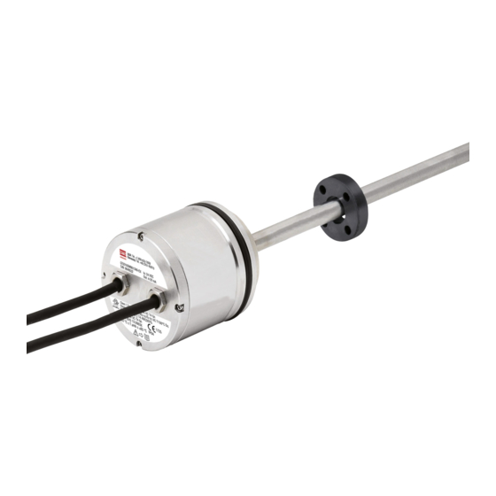
Page 9: Gte
Temposonics GTE Analog ATEX / NEC / CEC ® Operation Manual 4.2 Styles and installation of Temposonics ® GTE Analog ATEX / NEC / CEC Sensor electronics housing Null zone Stroke length Dead zone 56.8 37.5 50…2540 63.5 (1.1) (2.24) (1.48) (2…100) (2.5) -
Page 10: Frequently Ordered Accessories
Temposonics GTE Analog ATEX / NEC / CEC ® Operation Manual 4.4 Frequently ordered accessories – Additional options available in our Accessories Guide 551444 Position magnets Magnet spacer Ø 32.8 Ø 32.8 Ø 31.8 (Ø 1.29) Ø 25.4 Ø 4.3 (Ø... -
Page 11: Safety Screw
Temposonics GTE Analog ATEX / NEC / CEC ® Operation Manual 6. Inspection, maintenance, others 5.3 Safety screw A M5×10 set screw to ISO 4026 with flat point should be used. This 6.1 Assembly, disassembly safety screw is only required for blocking the sensor housing in axial direction and needs to butt only against the groove, i.e. -
Page 12: Technical Data Temposonics ® Gte Analog Atex / Nec / Cec
Temposonics GTE Analog ATEX / NEC / CEC ® Operation Manual 7. Technical data Temposonics GTE Analog ATEX / NEC / CEC ® Output Voltage 0…10 VDC, 10…0 VDC, −10…+10 VDC, +10…−10 VDC (minimum controller load: > 5k Ω) Current 4…20 mA, 20…4 mA, 0…20 mA, 20…0 mA (minimum/maximum load: 0/500 Ω) Measured value... -
Page 13: Certifications
Temposonics GTE Analog ATEX / NEC / CEC ® Operation Manual 8. Certifications Certifi cation required GTE-xxxxx-Bxx-1-xx-EX (+24 VDC (–15/+20 %)) IECEx / ATEX Ex nA IIC T4 Gc (IECEx: Global market; Zone 2 ATEX: Europe) −40 °C ≤ Ta ≤ +75 °C (−40 °F ≤ Ta ≤ +167 °F) Class I/II/III Div 2 T4 (USA) Groups ABCDEFG... -
Page 14: Appendix
Don’t specify chemical formulas. In the event of suspected penetration of substances into the sensor, Please include safety data sheets of the substances, if applicable. consult MTS Sensors to determine measures to be taken before shipment. Short description of malfunction:... - Page 15 MTS, Temposonics and Level Plus are registered trademarks of MTS Systems Corporation in the United States; MTS SENSORS and the MTS SENSORS logo are trademarks of MTS Systems Corporation within the United States. These trademarks may be protected in other countries. All other trademarks are the property of their respective owners. Copyright © 2021 MTS Systems Corporation. No license of any intellectual property rights is granted.
Need help?
Do you have a question about the Temposonics G Series and is the answer not in the manual?
Questions and answers