Table of Contents
Advertisement
Quick Links
Advertisement
Table of Contents

Related Manuals for Valleylab Force 2


Summary of Contents for Valleylab Force 2
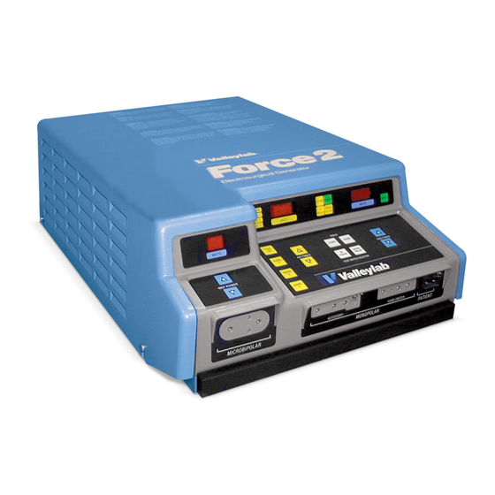
- Page 1 User’s Guide Force ™ Electrosurgical Generator...
-
Page 2: Foreword
Force™ 2, PolyHesive™ and REM™ are trademarks of Valleylab. ® Teflon is a registered trademark of E.I. DuPont de Nemours & Co. The Force 2 is protected by one or more of the following U.S. patents and their foreign counterparts: 4,632,109, 4,658,819, 4,658,820, 4,827,927, 5,190,517. Manufactured by:... -
Page 3: Introduction
Introduction The Force 2 PCH generators are designed to provide the three most significant electrosurgical effects: cutting, desiccation, and fulguration. The Force 2 generator provides both monopolar and microbipolar outputs for electrosurgery. The monopolar outputs are designed with the capability of delivering smooth cutting, cutting with increasing degrees of hemostasis, desiccation, and fulguration with minimum cutting. -
Page 4: Conventions Used In This Guide
To reduce the risk of electric shock, do not remove cover. Refer servicing to qualified service personnel. The generator is high frequency isolated per IEC 60601-2-2 DANGER Explosion Hazard: Do not use in the presence of flammable anaesthetics. Force 2 User’s Guide... -
Page 5: Valleylab Service Centers
Ph: 39 02 212181 Quebec, CANADA H4R 2A2 Fax: 39 02 2640059 Ph: 514-334 -7602 Fax: 514-331-5983 Tyco Healthcare Spain S.L. C/Fructuos Gelabert, 6 – 8 planta 8a, 08970 – Saint Joan DESPI Barcelona SPAIN Ph: 34-93-680-3370 Fax: 34-93-680-2457 Force 2 User’s Guide... -
Page 6: Table Of Contents
Section 2. Installation Inspect the Generator Responsibility of the Manufacturer Preparing the Generator for Use Power Requirements Check the Power Connector Ensure Proper Grounding Routine Maintenance Cleaning Instructions Section 3. Description of Controls, Indicators, and Receptacles Controls Indicators Force 2 User’s Guide... - Page 7 Alarms Receptacles Rear Panel Functions Section 4. Instructions for Use Setting Up the Force 2 Generator for Surgery Common Generator/Accessory Setups During Surgery Monopolar Electrosurgery Microbipolar Electrosurgery Recommendations During Surgery Typical Power Settings Low Power Settings Low Voltage Coag Changing Power Settings...
- Page 8 Force 2-2 PCH Generator Force 2-8 PCH Generator High Frequency Risk Parameters Low Frequency Leakage (50-60 Hz) Force 2-2 PCH Generator Force 2-8 PCH Generator (IEC 60601-1, Section 19 for Class 1 Equipment) REM Contact Quality Monitor Audio Volume Approximate Weight...
-
Page 9: Section 1. Patient And Operating Room Safety
Force 2 User’s Guide... - Page 10 Valleylab recommends against the use of laparoscopic surgery on pregnant patients. Do not use electrosurgical equipment unless properly trained to use it in the specific procedure being undertaken.
-
Page 11: Fire Hazard With Oxygen Circuit Connections
Protective impedances (resistors or RF inductors) installed in the monitoring leads may reduce the risk of such burns. Consult the hospital biomedical engineer for further information. Force 2 User’s Guide... -
Page 12: Ensure Proper Connections
• In addition, place patient return electrodes according to the manufacturer's instructions. Potential for alternate site burns increases if the return electrode is compromised. Valleylab recommends the use of REM patient return electrodes and Valleylab generators with the REM System. Ensure Proper Connections... -
Page 13: Before Surgery
Do not reuse or resterilize accessories labeled "disposable" or "single use only." Patient Return Electrodes Valleylab recommends the use of REM patient return electrodes and Valleylab generators with the REM system. Warning The safe use of monopolar electrosurgery requires proper placement of the patient return electrode. -
Page 14: Generator
(s-cord) to direct the current back to the generator, you must also use a Valleylab E0507-B adapter. To avoid a REM alarm, you must use a REM patient return electrode with the E0507-B adapter. -
Page 15: During Surgery
Do not activate the generator until the forceps have made contact with the patient. Product damage may occur. Suction Coagulators Warning To avoid the possibility of a burn to the surgeon, always place the generator in the standby mode prior to bending or reshaping the coagulator suction tube. Force 2 User’s Guide... -
Page 16: Active Accessories
Caution Studies have shown that smoke generated during electrosurgical procedures can be potentially harmful to surgical personnel. These studies recommend using surgical masks and ventilating the smoke by using a surgical smoke evacuator or other means. Force 2 User’s Guide... -
Page 17: Patient Return Electrodes
(cut mode) to lessen the potential for the creation of capacitive currents. • Carefully insert and withdraw active electrodes from cannulas to avoid possible damage to the devices and/or injury to the patient. Force 2 User’s Guide... -
Page 18: After Surgery
Do not reuse or resterilize accessories labeled "disposable" or "single use only." Notice Do not clean the generator with abrasive cleaning or disinfectant compounds, solvents, or other materials that could scratch the panels or damage the generator. 1-10 Force 2 User’s Guide... -
Page 19: Section 2. Installation
Valleylab • electrical installation of the relevant room complies with local codes and regulatory requirements such as IEC and BSI • equipment is used in accordance with the Valleylab instructions for use Force 2 User’s Guide... -
Page 20: Preparing The Generator For Use
The Force 2-8 PCH Electrosurgical Generator is designed to operate at 220-240 Vac nominal, 50-60 Hz. Check the Power Connector The Force 2 generator is supplied with a hospital grade power cord and a three-prong power connector. If using the generator in an operating room with another type of receptacle: •... -
Page 21: Ensure Proper Grounding
Ensure Proper Grounding Important It is the user's responsibility to To ensure patient safety, the Force 2 generator must be properly grounded. ensure that the electrical installation The ground wire in the power cord connects to the unit chassis and of the relevant room complies with ensures that no dangerous currents flow from the unit in the event of... - Page 22 Notes Force 2 User’s Guide...
-
Page 23: Section 3. Description Of Controls, Indicators, And Receptacles
Receptacles The controls, indicator, and receptacles for accessories are located on the front panel of the Force 2 Unit. This section describes each component of the unit and its function. Detailed procedures for setting up the unit are in Section 4. - Page 24 PCH Generator Front View PCH Generator Rear View MONOPOLAR FOOTSWITCH 250V, F8.0A - (110-120) FOREIGN EQUIVALENTS AND BIPOLAR 250V, F6.3A - (220-240) U.S. PATENTS: 4416276, 4416277, FOOTSWITCH 4632109, 4658819, 4658820, WARNING: RISK OF FIRE. 4827927 REPLACE FUSE AS MARKED. Force 2 User’s Guide...
-
Page 25: Controls
– Press this button to select cut with minimum hemostasis. Blend 1 – Press this button to select cut with moderate hemostasis. Blend 2 – Press this button to select cut with maximum hemostasis. Blend 3 Force 2 User’s Guide... -
Page 26: Indicators
– This indicator illuminates and the alarm tone sounds Remote Indicator once when the power control feature activates. When this indicator illuminates, power changes can be made using the power control handswitching pencil. Force 2 User’s Guide... -
Page 27: Alarms
– This receptacle accepts the three-pin Monopolar Active Receptacle (Handswitch) handswitching active accessories and the Valleylab power control pencil. Power output from this receptacle is activated only by using the handswitch mechanism. No power is available through use of the footswitch. -
Page 28: Rear Panel Functions
– Press the toggle upward to turn power on and down to shut On/Off Switch power off. The Force 2 generator uses a universal type power entry module but is not voltage selectable. Line fuse replacement is the following: 250V... -
Page 29: Section 4. Instructions For Use
Biomedical Department. 3. If necessary, connect the footswitch to the generator rear panel. You can connect a Valleylab monopolar two-pedal footswitch and/or a bipolar single-pedal footswitch to the generator rear panel. Connect the monopolar footswitch to the Monopolar Footswitch receptacle. - Page 30 To safely shunt the current to the generator, use a shunt cord that requires a special Valleylab adapter, and use a REM patient return electrode. Capacitive pads – Do not use capacitive pads because of the potential of high impedance at the patient and return pad interface.
- Page 31 Setting Up the Force 2 Generator for Surgery Warning The Accessory receptacle is designed for connecting either a handswitch (three- pin) or footswitch (one-pin) accessory, but not both at the same time. Connecting more than one accessory to the Accessory receptacle will activate both accessories simultaneously.
-
Page 32: Common Generator/Accessory Setups
Common Generator/Accessory Setups Microbipolar Output REM indicator illuminates but does not affect bipolar operation. Bipolar Handswitching or Footswitching Forceps Monopolar Handswitching Output Patient Return Electrode Handswitching Pencil/Forceps or Power Control Pencil Simultaneous Coag Patient Return Electrode Handswitching Pencil Force 2 User’s Guide... - Page 33 Common Generator/Accessory Setups Monopolar and Bipolar Setup Patient Return Electrode Bipolar Forceps Handswitching Pencil Monopolar Footswitching Output Patient Return Electrode Footswitching Accessory Force 2 User’s Guide...
-
Page 34: During Surgery
Avoid unnecessary and prolonged activation of the generator to reduce the possibility of alternate site burns that may be caused by RF leakage currents. When using multiple accessories, keep the cables separate. To reduce cross coupling, do not twist, bundle, or clamp the cables together. Force 2 User’s Guide... -
Page 35: Typical Power Settings
• Ablative cancer surgery, mastectomies, etc. (cut 180W to 200W; coag 70W to 75W). If the proper setting is not known from personal experience, one should set the generator at a very low setting and cautiously increase power until the desired effect is achieved. Force 2 User’s Guide... -
Page 36: Low Power Settings
Hold the Ready button and press the Coag Power Down button, just as low voltage coag was activated originally. The “L” in the coag power setting display disappears, signalling that the coag mode with the higher voltage (high crest factor) is set for fulguration. Force 2 User’s Guide... -
Page 37: Changing Power Settings
During Surgery Changing Power Settings When the surgeon activates the Force 2 generator, you cannot change the power settings. To change a power setting after the surgeon discontinues activation, press the appropriate Up or Down buttons until the desired setting appears on the power display. -
Page 38: Activating Accessories
Caution Do not activate the generator until the forceps have made contact with the patient. Product damage may occur. 4-10 Force 2 User’s Guide... -
Page 39: Section 5. Operating Room Troubleshooting
Inspect the plug pin to ensure it is not bent or missing. Carefully reinsert the plug into the Patient receptacle. Ensure that the pin goes into the hole and that the plug fully inserts. If the alarm condition is not corrected, proceed to step 2. Force 2 User’s Guide... - Page 40 If the alarm condition is not corrected, place the generator in the standby mode. Unplug the patient return electrode from the generator. Do not remove the return electrode from the patient. Proceed to step 4 or 5. Original application Application 2 Force 2 User’s Guide...
- Page 41 Application 3 Original application Application 2 Use a Multiple Return Adapter. Insert a Valleylab Multiple Return Adapter into the Patient receptacle. Place the generator in the ready mode. Insert the plugs of two patient return electrodes which have already been applied into the adapter. Choose the two return electrodes which are on the most vascularized, convex areas, in closest proximity to the surgical site.
-
Page 42: No Output
(low voltage coag or cut). If interference continues when the generator is activated and while the active electrode is not in contact with the patient, the monitor is responding to radio frequencies. Some manufacturers offer RF choke Force 2 User’s Guide... -
Page 43: Neuromuscular Stimulation
Always monitor pacemaker patients during surgery. Always keep a defibrillator available during electrosurgery on patients with pacemakers. Consult the pacemaker manufacturer for specific recommendations. Force 2 User’s Guide... - Page 44 Notes Force 2 User’s Guide...
-
Page 45: Section 6. The Rem Contact Quality Monitoring System
The REM contact quality monitor is not able to monitor the patient contact area if conventional, single-section patient return electrodes are used. Force 2 User’s Guide... -
Page 46: Adaptive Rem Monitoring
If the patient-to-pad impedance increases 40% above this reference value or above 135 ohms, the REM alarm sounds and the monopolar output is disabled. The adaptive REM system is designed to calibrate itself with respect to each patient. Force 2 User’s Guide... -
Page 47: Appendix A. Technical Specifications
Humidity Range 30% to 75%, noncondensing Atmospheric Pressure 500 to 1060 millibar Storage and Shipping Temperature Range -18°C (0° F) to 70° C (158° F) Humidity Range 10% to 100%, noncondensing Atmospheric Pressure 500 to 2500 millibar Force 2 User’s Guide... -
Page 48: Output Waveform
3.4 @ 100W Blend 2 4000 3.9 @ 100W Blend 3 4000 4.7 @ 100W Coag 7000 8.5 @ 50W Low Voltage Coag 4000 4.7 @ 99W Bipolar 1200 2.0 @ 40W Output Configuration Isolated output. Force 2 User’s Guide... -
Page 49: Input Power Source
Input Power Source Input Power Source Force 2-2 PCH Generator Maximum Operating Range 85-135 Vac Nominal Operating Range 110-120 Vac The line frequency may vary between 45 and 65 Hz Current: Idle - 0.7A, max Power: Idle - 60W, max Cut - 7.0A, max... -
Page 50: Force 2-2 Pch Generator
< 59 mA, per IEC 60601-2-2. Monopolar RF leakage current: < 150 mA, per IEC 60601-2-2. Low Frequency Leakage (50-60 Hz) Force 2-2 PCH Generator All patient connected terminals tied together: Source current normal polarity, intact chassis ground < 10 µA Source current normal polarity, ground open <... - Page 51 Classification Type CF Equipment per IEC 60601-1 The Force 2 provides a high degree of protection against electrical shock, particularly regarding allowable leakage current and has a CF type isolated (floating) applied part. The applied part may be used on the heart.
- Page 52 IEC 60601-2-2, Figure 104. PCH Generator Typical Output Pure Cut Power vs Load—Monopolar Cut Modes Generator Power Setting 300 W 150 W Impedance (ohms) Blend 1 Generator Power Setting 250 W 125 W Impedance (ohms) Force 2 User’s Guide...
- Page 53 Classification PCH Generator Typical Output Power Blend 2 vs Load—Monopolar Cut Modes (continued) Generator Power Setting 200 W 100 W Impedance (ohms) Blend 3 Generator Power Setting 150 W 75 W Impedance (ohms) Force 2 User’s Guide...
- Page 54 Classification PCH Generator Typical Output Coag Power vs Load—Monopolar Coag Modes Generator Power Setting 120 W 60 W Impedance (ohms) Low Voltage Coag Generator Power Setting 250 W 125 W Impedance (ohms) Force 2 User’s Guide...
- Page 55 Bipolar measurements are made using bipolar forceps on the insulating surface referred to in IEC 60601-2-2, Figure 104. PCH Generator Typical Output Power Bipolar vs Load—Bipolar Mode Generator Power Setting 70 W 35 W 15 W Impedance (ohms) Force 2 User’s Guide...
- Page 56 Notes A-10 Force 2 User’s Guide...
- Page 57 Valleylab’s satisfaction, that the product is defective. This warranty does not apply to any product, or part thereof, which has been repaired or altered outside Valleylab’s factory in a way so as, in Valleylab’s judgment, to affect its stability or reliability, or which has been subjected to misuse, neglect, or accident.
- Page 58 Valleylab’s liability with respect to this agreement and products sold hereunder shall be limited to the aggregate purchase price for the goods sold by Valleylab to the customer. There are no warranties which extend beyond the terms hereof. Valleylab disclaims any liability hereunder or elsewhere in connection with the sale of this product, for indirect or consequential damages.
Need help?
Do you have a question about the Force 2 and is the answer not in the manual?
Questions and answers