Samsung S23A750D Service Manual
Liquid crystal display
Hide thumbs
Also See for S23A750D:
- Manual del usuario (90 pages) ,
- User manual (88 pages) ,
- User manual (46 pages)
Table of Contents
Advertisement
Quick Links
Advertisement
Table of Contents

Related Manuals for Samsung S23A750D


Summary of Contents for Samsung S23A750D
- Page 1 Liquid crystal display Chassis: WDQ2 Model: S23A750D S27A750D Service Manual Thin film liquid crystal displays Contents 1. Matters needing attention 2. Product specifications 3. Disassembly and reassembly 4. Troubleshooting 5. Wiring diagram S23A750D / S27A750D...
-
Page 2: Table Of Contents
Table of Contents 1. Matters needing attention ....................... 1-1 1-1 Security considerations........................ 1-1 1-2 Maintenance considerations......................1-2 1-3 Electrostatic sensitive device considerations.................. 1-3 1-4 Installation notes......................... 1-3 2. Product specifications ........................2-1 2-1 Features and specifications ......................2-1 2-2 Compared with the old model specifications.................. 2-2 2-3 Annex............................ - Page 3 The repair manual, Samsung Electronics Co., Ltd. all. © 2011 Samsung Electronics Co., Ltd. Unauthorized use of this manual may be subject to All rights reserved applicable international and/Or domestic legal punishment. 中国印刷...
- Page 4 1. Precautions 1. Precautions 1-1. Safety Precautions Follow these safety, servicing and ESD precautions to prevent damage and to protect against potential hazards such as electrical shock. 1-1-1. Warnings For continued safety, do not attempt to modify the circuit board. Disconnect the AC power and DC power jack before servicing.
- Page 5 1-1-4. Product Safety Notices Some electrical and mechanical parts have special safetyrelated characteristics which are often not evident from visual inspection. The protection they give may not be obtained by replacing them with components rated for higher voltage, wattage, etc. Parts that have special safety characteristics are identified by on schematics and parts lists.
- Page 6 1. Precautions 1-3. Static Electricity Precautions Some semiconductor (solid state) devices can be easily damaged by static electricity. Such components are commonly called Electrostatically Sensitive Devices (ESD). Examples of typical ESD are integrated circuits and some field-effect transistors. The following techniques will reduce the incidence of component damage caused by static electricity. 1.
-
Page 7: 2. Product Specifications
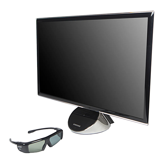
- FHD 120Hz 3D compatibility, 16:9 aspect ratio, high DCR, software optimized to Windows 7, low power consumption, and more Specifications Item Description Model S23A750D S27A750D LCD Panel TFT-LCD panel, RGB vertical stripe, normally white transmissive 23” Wide viewable 27” Wide viewable 0.2655(H) x 0.2655(W) mm pixel pitch... - Page 8 Active Display 509.76 (H) x 286.74 (V) 597.6 (H) x 336.15 (V) (Horizontal/Vertical) AC power voltage & AC 110 ~ 240V, 50 ~ 60 Hz Frequency Power Consumption Typical 45 W / Max 48 W Typical 53 W / Max 56 W DPMS: Typical 1 watt / Max 1 watt DPMS: Typical 1 watt / Max 1 watt Dimensions Set...
- Page 9 2-2. Spec Comparison to the Old Models [SA750] [CREAM] Model S23A750D / S27A750D 2233RZ Design 23 "/27" Size 22 " Resolution 1920 X 1080 1680 X 1050 MEGA 20,000:1 DVI-DL IN/OUT HDMI HP-OUT 3D format compatible 2D -> 3D 3D game...
- Page 10 2-3. Accessories Product Description Code. No Remark Safety Guide BN68-03413A Warranty Card BH68-00344C (Not available in all locations) User Manual BN68-03632B Cleaning Cloth BN63-02368B Samsung Electronics Service center Adapter BN44-00461A Power Cord 3903-000598 DP Cable BN39-01501A 3D Glasses Assy BN96-18236A...
-
Page 11: 3. Disassembly And Assembly
3. Disassembly and reassembly Repair manual this chapter describes the display disassembly and reassembly step. Warning This display contains electrostatic sensitive devices. Should use caution when handling these parts. 3-1. Disassembly Be careful: 1. As before, please turn off the monitor. 2.When removing the display, do not use the open metal tools other than the tools provided. - Page 12 3.拆卸和重新组装 Introductions Photo caption 3. Disassembly 4 A screw. Scre 4 个 4. As backward tilt base as shown in the figure. 5. Removal of the mark shown LVDS Wiring.
- Page 13 Introductions Photo caption 6. Remove the front cover as shown in the figure. 7. As shown in Figure remove rear cover.
- Page 14 3.拆卸和重新组装 Introductions Photo caption 8. Release 5 Screws and remove the base cover. Scre 5 个 9. Release 4 Screws, and remove the printed circuit board. Scre 4 个 Introductions Photo caption...
- Page 15 10. As shown in diagram disassembly and fan hub. 11. As shown in the figure and remove LVDS Wiring and printed circuit boards.
- Page 16 3.拆卸和重新组装 Introductions Photo caption 12. Release 4 A screw, and remove the hinge at the neck and the base cover. Scre 4 个 13. As shown in the figure, and remove it from the base frame the base Central cover.
- Page 17 Introductions Photo caption 14. Release 2 Screws, and remove the fan. Scre 2 个 *Reassembly step and disassembly steps instead. Screw size Code number A (mm) B (mm) C (mm) number 6001-001114 4 EA 6003-000264 4 EA 6003-001374 4 EA 6006-001096 2 EA 6003-001785...
-
Page 19: Troubleshooting
4 故障排除 4 Troubleshooting 4-1. Troubleshooting 1. In front of the repair, set the custom mode as follows: - Resolution:1920×1080 - Horizontal frequency:67.5 kHz - Vertical frequency:60 Hz 2. If no image appears, ensure that the power cables are properly connected. 3. -
Page 20: When The Power Supply Is Not Available
4 故障排除 4-2 When the power supply is not available -After connecting the power supply turn on the power button, the front of Sign the monitor LED is not running. -Check the screens at the back of the monitor power switch is turned on. Mainly a -Check whether the adapter and connector are connected correctly. - Page 21 4 故障排除 IC204 Q208 CN100 Main PBA – 1st Floor_Bottom Q630 IC201 IC203 IC202 Main PBA – 2st Floor_Top...
- Page 22 4 故障排除 IC501 IC502 IC505 CN504 Main PBA – 2st Floor_Bottom CN100 IC504 4-2-1 When power is not available in the circuit diagram ( 1 Circuit)
- Page 23 4 故障排除...
- Page 24 4 故障排除 4-2-2 When power is not available in the circuit diagram ( 2 Circuit)
- Page 25 4 故障排除 MM3374A25PRH R537 R539 C53110UF 1OHM 1OHM 6.3V C537 C539 10UF 10UF 6.3V 6.3V FGND FGND FGND FGND...
- Page 26 4 故障排除...
-
Page 27: When You Monitor Black Screen
4 故障排除 4-3. When you monitor black screen (HDMI) -当 HDMI When the wiring is connected, the power LED Is on and the screen Sign black screen or W/R/G/B Pattern interruption-style display. -Scrutineering HDMI Wiring connections. Mainly a -Scrutineering LVDS The wiring is correctly connected to the Panel. checkpoint -Check 1 Layer and 2 Between connector and 60 针... - Page 28 4 故障排除 HDMI 60 FFC Cable ↔ ↔ Connector Connector CN401 4-3-1. Black screen appears when the circuit diagram (HDMI) 4-10...
- Page 29 4 故障排除 HDMI INPUT 4-11...
- Page 30 4 故障排除 4-3-2. Screen no display of HDMI 4-12...
-
Page 31: When You Monitor Black Screen
4 故障排除 4-4. When you monitor black screen (DP) -当 DP When the wiring is connected, the power LED Is on and the screen black Sign screen or W/R/G/B Pattern interruption-style display. -Scrutineering DP Wiring connections. Mainly a -Scrutineering LVDS The wiring is correctly connected to the Panel. checkpoint -Check 1 Layer and 2 Between connector and 60 针... - Page 32 4 故障排除 ↔ Connector 60 FFC Cable ↔ Connector CN401 4-4-1. Black screen appears when the circuit diagram (DP) 4-14...
- Page 33 4 故障排除 4-4-2. Screen no display of waveforms (DP) 4-15...
- Page 34 4 故障排除 4-16...
-
Page 35: Examples Of Faults And Corrective Actions
4 故障排除 4-5. Examples of faults and corrective actions Failure pictures Symptoms and corrective actions Notes Symptom: when you turn the monitor on, regardless of whether there is signal, continuous display of full white pattern. Reason: an LVDS Connection failure or error connections. -
Page 36: Regulation
4 故障排除 4-6. Regulation 4-6-1. Conditions of repairs Maintenance considerations for adjusting Check for repairs if the device is functioning properly. 1) In order to secure large enough to remove the display. 2) Prepare a cushion before the demolition. 3) Enter maintenance mode Enter: Exit:... - Page 37 4 故障排除 4-6-2. Maintenance of functional specifications ■ Checking the version code 1. In SVC Model checking MCU Code revision and inspection. 2. In SVC Model Adjust the brightness and contrast values for 0。 Press enter five (5) Seconds SVC Function OSD On the show. If you want to exit SVC Function, turn off the power.
- Page 38 4 故障排除 ■ Maintenance mode (move) Button to move to the other options. ▼ 1.Press Button, change the setting to on or off. ▲ 2.Press 4-20...
- Page 39 4 故障排除 ■ When panels are replaced Replace the Panel, select a Panel item and press the menu button five (5) Seconds. Plate surface Ch. No will increase 1 and time information will be changed to 0。 This number increased 1 4-21...
- Page 40 4 故障排除 4-6-3. Enter DDC (MTI-2510) WinDDCU Pop-up menu Pop-up menu Function EDID Logger Run a recorder and verified by computer on the monitor EDID Data (*.ddc) File. The menu is mainly being used to enter EDID Data files (*.ddc) For more information.
- Page 41 - Bar code write mode: reading the serial number barcode and direct the writing process. The implementation of EDID Logger 1.The implementation of[Load file], And select a ddc File input for more information. DDCFile name S23A750D S27A750D SMS23A750DH.ddc SMS27A750DH.ddc 4-23...
- Page 42 4 故障排除 Select an input port and mode Don't forget to check these locations!! 2.Check the loading process→Display a confirmation, click on the[Logger]Begin writing. 3.Write to complete. In factEDID The writing process was not complete at this stage. 4-24...
- Page 43 4 故障排除 4.Click Verify. Because of the tests included in the writing process, this option can be selected is not enforced. DDC Data backup 1. 在 EDID Selected in the formula bar[Read]。 2. Enter a file name and keep the backup data. 4-25...
- Page 44 4 故障排除 3. DDC Data backup is complete. DDC Data backup requirements are as follows. -When many of the same model is used, you should check DDC Files for defects. Run EDID Multi-purpose logger (for analog and HDMI Input signal) 1.
- Page 45 4 故障排除 2.Check the loading process→Display a confirmation, click on the[Logger and verify]。 3.EDID Multi-purpose logger process to complete. 4-27...
- Page 46 4 故障排除 4-6-4.Enter EDID Connection Connection DDC Manager to your computer; next, use DVI 或 HDMI Wiring connections DDC Manager to the display. Menu 4-28...
- Page 47 3. Choose[Write]Buttons. 4. If EDID Upgrade intact, you can see the following information. *DP EDID Has been included in the MICOM , So you don't need to upgrade DP EDID。 DDCFile name S23A750D S27A750D SMS23A750DH.ddc SMS27A750DH.ddc 4-6-5.Enter Micom Connection Connection DDC Management devices to your computer USB Port connect HDMI-DVI Connection to DDC Management unit and the back of the product HDMI Port.
- Page 48 4 故障排除 1. ChooseManufactureSelectMicomConstructor. 2. Select the type of device. 3. Select the input port. 4. Select external memory storage capacity. 4-6-6.Enter the code (HDCP) 1.Runservice.exeFile. 4-30...
- Page 49 4 故障排除 2.Click on the HDCP Buttons. 3.点击 HDCP 写入按钮并选择 Mstar_HDCPKEY。 4-31...
- Page 50 4 故障排除 4.输入 HDCP 密钥已完成。 4-32...
-
Page 51: 5. Wiring Diagram
5. Wiring Diagram 5. Wiring Diagram... - Page 52 5. Wiring Diagram 5-1. Wiring Diagram Schematic...
-
Page 53: Power Flow Chart
5. Wiring Diagram 5-2. Power Flow Chart 5-3. Board Connection Main PBA – 1st Floor... - Page 54 5. Wiring Diagram Location Block Functions LVDS connector between the 1st and 2nd Connects the LVDS signal from the 1st floor to the 2nd floor floors Receives and bypasses the LVDS 4 channel input, creates the 148.5MHz FPGA output, and puts the output into the M180 system clock on the 2nd floor DDR3 Starts the scaler Scaler...
- Page 55 5. Wiring Diagram LED Driver Turns on the backlight of the LED panel 1 ↔ 2 LVDS Connector AU_MCLK LVDS_TX2_DN DP Signal Input Connector AU_SCLK LVDS_TX2_CP DP_LANE3- AU_LRCLK LVDS_TX2_CN DP_LANE0+ AU_SDOUT LVDS_TX2_BP DP_LANE3+ LVDS_TX2_BN DP_LANE2- LVDS_TX4_DP LVDS_TX2_AP DP_AUX+ LVDS_TX4_DN LVDS_TX2_AN DP_LANE2+ LVDS_TX4_CP DP_LANE1-...
- Page 56 5. Wiring Diagram HDMI_RX0+ HDMI_DPMS HDMI_CHK HDMI_RX0- HDMI_RXC+ 1 ↔ 2 B-to-B Connector VLED1 LED6 LED3 LED5 LED2 LED4 LED1 VLED3 +14V SUB_SDA +14V SUB_SCL +14V DPMS_ON HP_MUTE PANEL_EN +5V_PANEL Function + BT Connector BT_TEST ENABLE_3D EMIT_3D_SYNC +3.3V_FUNC USB_P USB_N FUNC_SDA +5V_BT FUNC_SCL...
- Page 57 Connects the LVDS signal from the 1st floor to the 2nd floor floors DDR1 Starts M180 M180 This Samsung patent-applied IC starts the 3D function. DDR1 Starts M180 LVDS Connector Connects the LVDS 4 channel and LED driver signal panel...
- Page 58 5. Wiring Diagram Power Adaptor Connector 1 ↔ 2 LVDS Connector +14V_VCC AU_MCLK LVDS_TX2_DN AU_SCLK LVDS_TX2_CP AU_LRCLK LVDS_TX2_CN AU_SDOUT LVDS_TX2_BP LVDS_TX2_BN LVDS_TX4_DP LVDS_TX2_AP LVDS_TX4_DN LVDS_TX2_AN LVDS_TX4_CP Headphone Out Connector LVDS_TX4_CN LVDS_TX2_CLKP LVDS_TX4_BP LVDS_TX2_CLKN HP_L_OUT LVDS_TX4_BN HP_L_OUT LVDS_TX4_AP LVDS_TX1_DP HP_R_OUT LVDS_TX4_AN LVDS_TX1_DN HP_R_OUT LVDS_TX1_CP...
- Page 59 5. Wiring Diagram B_RXE1P F_RXECP F_RXO0N B_RXE1N F_RXECN SDATA B_RXE0P SCLK B_RXE0N F_RXE2P F_RXE2N VCC_LED2 B_RXO3P F_RXE1P VCC_LED1 NC(Sync_o) B_RXO3N F_RXE1N BIST_EN F_RXE0P NC(ELIT_EN) B_RXOCP F_RXE0N PWMI B_RXOCN Frame_sel F_RXO3P B_RXO2P F_RXO3N VIN_5V B_RXO2N VIN_5V...
-
Page 60: Connector Function
5. Wiring Diagram Main PBA – Coupling struc ture 5-4. Connector Functions Connector Functions CN301 (1st floor) HDMI signal input port * Failure symptoms: No HDMI Output error may occur. CN302 (1st floor) DP signal input port * Failure symptoms: No DP Output error may occur. CN100 (1st floor) Port that connects the power and signals between the 1st and 2nd floors * Failure symptoms: No Power error may occur or the LED backlight may not turn on. - Page 61 5. Wiring Diagram CN400 (1st floor) Port that connects the LVDS signal between the 1st and 2nd floors * Failure symptoms: Panel Test Pattern (W/R/G/B) may appear repeatedly. CN504 (2nd floor) 14V power input port that connects the power and signals between the 1st and 2nd floors * Failure symptoms: No Power error may occur or a function may not work.