
Subscribe to Our Youtube Channel
Related Manuals for PRECITEC CHRocodile C

Summary of Contents for PRECITEC CHRocodile C
- Page 1 CHRocodile C Compact sensor for non-contact distance and thickness measurement Operation Manual...
- Page 2 It may not be reproduced or used in a manner contrary to the company’s legal interests without prior written approval of Precitec Optronik GmbH. It is strictly intended for use in the context of service operations. Any other use is impermissible. Any sharing of this documentation with third parties requires the prior, expressed written approval of Precitec Optronik GmbH.
- Page 3 Version Control Version – Date Type of Change Manual 1.0.0.0 2016/09/20 Original edition...
-
Page 4: Table Of Contents
Table of Contents Table of Contents ......................4 Basic Safety Instructions ....................7 Warranty and Liability ..................7 Safety Symbols ....................7 Proper Use ......................8 Duty of Operator and Personnel ............... 9 Safety Measurements in Normal Operation ............. 9 1.5.1 Protection from Electronic Shock .................... - Page 5 Sensor unit characteristics ..................... 22 2.8.2 Optical probes characteristics ....................23 Optical Head Specifications definitions ............24 2.10 CHRocodile C performance specifications: ........... 26 Operational Start up ..................... 28 Connections and Interfaces ................28 CHRocodile Explorer and Drivers installations ..........30 Communication with CHRocodile C ..............
- Page 6 Appendix 2: Mechanical Plans ..................64 1. Optical probe mechanical plans ................ 64 2. CHRocodile C unit mechanical plans ..............66 3. CHRocodile C unit mechanical interface plans ..........67 Appendix 3: Trouble Shooting ..................68 1.1 Power off ......................68 1.2 Communication error: ..................
-
Page 7: Basic Safety Instructions
Precitec Optronik GmbH apply to all of our products. We reserve the right to make any changes to the device’s construction for reasons of improving quality or expanding the possible applications as well as any made for production-related reasons. -
Page 8: Proper Use
ARNING Do not touch – indicates that touching the contact/optics surface can cause damage/destruction of the component. MPORTANT Information which the user must pay attention to/ be aware of in order to avoid disruptions in the course of processing/ in product use. Provides information that the user needs in order to achieve the intended result of an action most directly and without difficulty. -
Page 9: Duty Of Operator And Personnel
use the original devices and replacement parts and observe the instructions for EMC-compliant installation in the handbooks that come with them. If the optical sensor is operated inside a facility with other devices, the entire facility must comply with the provisions in the EC-Guidelines in the demands of the general operating permit. -
Page 10: Grounding The Device
do not look directly into the LED’s light. The light can harm your eyes. 1.5.3 Grounding the device Make sure that the device is grounded in compliance with regulations. Please make sure that the optical sensor is supplied with power via a grounded main power input line (cold device plug). -
Page 11: Product Description
With its robust and integrated design, the CHRocodile C is ideally suited for industrial inline use and easily integrable into any kind of inspection machine. -
Page 12: Measuring Principle
2.3.1 Optical principle For most industrial applications the chromatically coded distance detection method turned out to be very well suited. CHRocodile C is based on this method and more precisely on the Confocal Chromatic principle. This principle combines the properties of confocality and axial chromatism. - Page 13 Fig. 2-2: Chromatic Confocal Imaging principle (point sensor)
-
Page 14: Sensor Functionalities
2.4 Sensor Functionalities The CHRocodile C can transmit two different data: distance and thickness measurements. The principle of these two applications are explained hereafter. Application type 1 Chromatic distance measurement Topographic, profile or roughness measurements are performed with distance data measurement. With single-point sensors, i.e. CHRocodile C, one spot is focused on the surface of the measured object using an optic with a known chromatic aberration. - Page 15 Application type 2 Chromatic thickness measurement Thickness measurements can be performed when thickness data is selected. If a transparent material is within the measurement volume of the chromatic optical probe, the white light spot is focused on both the two surfaces of the measured object. The reflected light is more intense for the two wavelengths in focus on the two surfaces.
-
Page 16: Typical Applications (Overview)
The PRECITEC confocal chromatic compact sensor is very well adapted to industrial environment, as no optical cable are connected to the CHRocodile C unit. The absence of optical cables, promotes robustness and compactness of the measuring device, and also facilitates the integration and use on a motorized moving system, such as a coordinate measuring machine (CMM). -
Page 17: List Of Deliverables
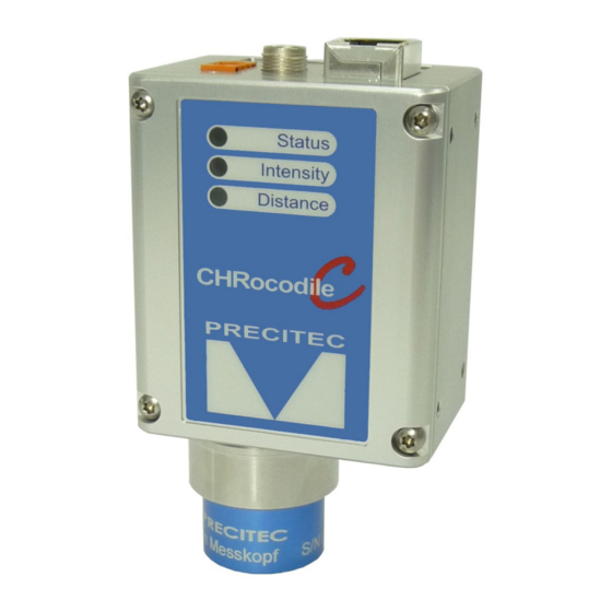
Power Supply Adapter (100-240V +/-10%), Ethernet cable, A CD with DLL and firmware, Software user guide, Operation Manual, Calibration report. Fig 2-5: CHRocodile C unit 3D view: Fig 2-6: Optical Head 3D view: a- 0.2mm b- 1mm c- 4mm d- 10mm... -
Page 18: Connections And Interfaces
The CHRocodile C has a RJ45 standard connector for Ethernet communication. Connect the isolated RJ45 standard connector from the CHRocodile C unit to an Ethernet network (PC). Ethernet supports the data transfer and can also be used for setting configuration by using $ command protocol (Cf. - Page 19 The interface contains the connection points for the synchronization and RS422 or RS232 serial communication. The serial RS232/RS422 is interfaced on the multipoint connector interface (9 pins). Serial communication are mostly used for sending command as a hyper-terminal, and can also support data transfer.
-
Page 20: External Analogue Converter Box Connection
The 8 pins round connector is used for external analogue converter box connection. This option can be added to the CHRocodile C in order to obtain an analogue output. Also it is possible to add up to 2 encoder-input using this external analogue converter box connection. -
Page 21: Status Led
2.7.5 Status LED LED status / CHRocodile C Status Power OFF Power ON, Firmware boot failure Power ON, Firmware is configured / Continuous measurement (blink) Power ON, Triggering session Power ON, Waiting for trigger green when triggered at high frequency... -
Page 22: Sensor Characteristics
5009276 Table 2.6: Sensor Characteristics (1) See section 2-3: Sensor functionalities. With CHRocodile C, the transmitted data are limited to up to 4 Altitudes, up to 4 Intensities and up to 3 Thicknesses. (2) See Fig A2-2 Sensor unit mechanical plan in Appendix 2 CHRocodile C unit mechanical plan. -
Page 23: Optical Probes Characteristics
(5) Measurement on perpendicular mirror at 20°C with optimal Signal to Noise ratio. (6) Axial Resolution varies with intensity signal in %. Axial Resolution = 10 x R -0.5 (7) Refractive index n=1.5 (8) See Fig A2-1: Optical probes mechanical plan (9) See Fig A2-2: CHRocodile C unit mechanical plan... -
Page 24: Optical Head Specifications Definitions
Considering this opto-mechanical architecture the CHRocodile C unit has no visible optical cable and the user don’t need to take care with this particularly sensitive component. -
Page 25: Chrocodile C Performance Specifications
Fig 2-9: Axial Resolution as a function of target position in measuring range. Accuracy: Accuracy corresponds to the altitude deviation between the CHRocodile C and a calibrated interferometric reference sensor as a function of target position in the measuring range. Consequently, accuracy is an experimental specification. - Page 26 Minimum and Maximum Measurable Thicknesses: The minimum and maximum measurable thickness specification is given for n=1.5 refractive index. It is measured on a standard sample in the center of measuring range. T=n x (D Fig 2-11: Minimum and maximum measurable thicknesses...
-
Page 27: Operational Start Up
Operational Start up 3.1 Connections and Interfaces All of the connection ports are located at the rear of the CHRocodile C (Cf. section 2.6 Connections and Interfaces): The power supply jack, The RJ45 standard connector for Ethernet communication, ... - Page 28 In addition to the Power supply and Ethernet connector or multipoint connector interface used for stand-alone device, the CHRocodile C needs to be connected to other interfaces to be integrated into complex measurement configuration systems. The other possible interfaces are described hereafter: The multipoint connector interface for Trigger Input/Output and Serial interface RS422, The 8 pins mini-DIN connector for external analogue converter box to add 2 encoder inputs.
-
Page 29: Chrocodile Explorer And Drivers Installations
There are three possible ways to communicate with the CHRocodile C: via Precitec CHRocodile Explorer software, via the CHRocodile C DLL and using the ASCII commands sent to the CHRocodile C through serial interface (RS 422) or Ethernet communication. Up to 10 CHRocodile C can be connected and controlled by a single computer (Windows XP, Windows 7 or Windows 8 OS, 32 and 64bits). - Page 30 3.3.2 Via CHRocodile C DLL: DLL is used to interface the sensor with a general-purpose user program. This CHRocodile C DLL is written in C, C++ language and is intended for .NET compatible language. This DLL allows to use whole CHRocodile C functionalities. In order to obtain further detailed refer to CHRocodile C DLL documentation.
-
Page 31: Measurements Start Up
The calibration table depends on both spectrometer and optical probe. Consequently a calibration table is specific to one set of CHRocodile C sensor (CHRocodile C unit + optical probe), it can’t be used on another set even if you are using the same optical probe type (i.e same measuring range). -
Page 32: Mechanical Interfacing
Fig 4-2: Interchangeable optical heads And, fixing the CHRocodile C on your system using the interface threaded M3 holes located on the soleplates and on the lateral surfaces of the CHRocodile C unit or using the ring surrounding the optical probe (Cf. Fig 4-3). -
Page 33: Basic Settings Configuration
2. 4.4 Basic Settings Configuration In order the CHRocodile C to be operational for startup some basic parameters should be set up. You can also refer to the CHRocodile C quick start guide documentation. Basic setting configuration consists in selection of: •... -
Page 34: Data Measurement Training
The measuring rate is related to data transmission frequency. The CHRocodile C maximum measuring rate is 4KHz. The higher the measuring rate is the lower the signal intensity is. Consequently, depending on the object reflectivity under measurement, the measuring rate (measuring frequency) must be adjusted in order to remove saturation or too low intensity signal. - Page 35 In order to record the data corresponding to the CHRocodile C unit, the Ethernet port or the RS422/RS232 communication port must be connected to the computer. It is now possible to perform an area scan: In order to scan the target, one can move the optical probe or the target inside optical axis perpendicular plan.
-
Page 36: Appendix 1: Advanced Configuration
Appendix 1: Advanced Configuration 1. Commands List command arguments answer on query comments <0,1>/<0..100> <0,1> <detector level> Auto Adapt Light source: or <?> First parameter: auto adapt on(1) or off(0, default) Second parameter, only needed in case first param is 1: desired detector level in % of saturation level (0-100), 33 is default. - Page 37 Detection WinDow <0..n1><0..n2> <0..n1><0..n2> Up to 16 windows (window1left, window1right, [<0..n1><0..n2>] [<0..n1><0..n2>] window2left, window2right...), in micrometers … See also: LMA <0..4> [<0..3>] ENCoder Position: < -2147483648 .. 4294967295, ?> $ENC <axis#> <function> <arg> -index of axis -optional: Function -position (treated modulo 2^32) Defined functions: •...
- Page 38 <0,?> <0,?> Measuring MoDe Only argument <0>, chromatic mode supported Number Of Peaks <1..4> <1..4> 1(default)-MaxNOP. The MaxNOP value is a characteristic of the device and can be read back by the IDE command. In confocal mode, if less than NOP peaks are detected, all thickness signals will be invalidated because peak identification is not possible.
- Page 39 <3..17, ?> <index of sample rate> set Sample Rate <sample rate in Hz>HZ Compatibility command 3:32Hz, 4:100Hz, 5:320Hz, 6:1000Hz, 7:2000Hz, 8: 3200Hz, 9: 4000Hz(default) See also: SHZ <refractive index> at Set/query Refractive Index <1..5> spectral d-line (587,567 Only active, if SRT 0 selected (no preloaded Index table) 1.0(default)-5.0 You should give as many indices as there are layers to be measured, that is (number of Peaks - 1).
- Page 40 mode. The first exposure start will occur immediately at the trigger. See also: TRE, TRW, CTN TRigger Window The device runs freely as long as the trigger condition is fulfilled. The first exposure start will occur immediately at the trigger See also: TRG, TRE, CTN VERsion Responds with a string containing several lines with...
-
Page 41: Detailed Commands Description
2. Detailed Commands Description 2.1 CTN Command This command lets the sensor exit any of the above trigger modes and returns to freerun. No parameters are needed, so the syntax is just $CTN. 2.2 DRK Command This command lets the sensor acquire a background spectrum that the incoming spectra will be corrected for during normal operation. -
Page 42: Etr Command
The following functions are defined: Arg1 Function Arg2 Set / Read current encoder counter value Encoder counter value to set Set count source 0: Pulse on A0, 1: Pulse on B0, 2: Pulse on A1 . . . 9: Pulse on B4 10: Pulse on SyncIn 11..14: not used 15: Quadrature A/B on encoder input <axis index>... - Page 43 This command groups several functions related to encoder triggering. The encoder trigger can work in two ways: 1. Roundtrip trigger (scanning application) 2. Endless trigger Roundtrip trigger (scanning application) The encoder trigger is implemented as a state machine (see figure below). In the idle state, it waits for the encoder counter of the selected axis to pass the start position (in either direction) where it generates the first trigger event.
- Page 44 Endless trigger This mode is destined for applications where the encoder primarily moves in one direction as in production lines and where equidistant sampling is needed. In order to use this mode, only a trigger interval has to be parametrized. Fig A1-2: Endless Trigger Format The command has the following format: ETR <function>...
-
Page 45: Ipcn Command
2.5 IPCN Command Short description: This command allows to configure TCP/IP address and subnet mask. Command syntax: $IPCN <DHCP> <IPA> <IPB> <IPC> <IPC> <MA> <MB> <MC> <MD> <MTU> Command Description $IPCN 1 Configured as DHCP client $IPCN <DHCP> $IPCN 0 192 168 170 4 255 255 255 0 0 Configured as static IP address $IPCN <DHCP>... -
Page 46: Nop Command
The $SEN command is used to activate the chromatic—confocal calibration related to a specific sensor head. With the single channel device, up to sixteen calibrations can be uploaded and stored in the device. With the Chrocodile C device, up to eight calibrations are supported. -
Page 47: Shz Command
The format of the command is as follows: $SEN n where n is the calibration table index. As the possible measuring range of each probe is much higher than the range for which it is specified and guarateed to adhere to the specifications, there is a way to use the full range with degraded precision. -
Page 48: Sodx Command
$SHZ 1000 Write Sample Rate (1000 Hz) Response: $SHZ 1000[CR]ready[CR/LF]. $SHZ ? Read Sample Rate Response: $SHZ ? 1000ready[CR/LF]. 2.11 SODX Command Short description: Select Output Data (extended) SODX directly selects the data words that will be included in the output telegram by specifying their indices. - Page 49 encoder position on beginning of Response: $SODX 66[CR]ready[CR/LF]. exposure) $SODX 67 Start of exposure PositionZ(Z encoder position on beginning of Response: $SODX 67[CR]ready[CR/LF]. exposure) $SODX 68 Start of exposure PositionU(U encoder position on beginning of Response: $SODX 68[CR]ready[CR/LF]. exposure) $SODX 69 Start of exposure PositionV(V encoder position on beginning of Response: $SODX 69[CR]ready[CR/LF].
- Page 50 Peak Signal: Definition: Bit 8 = 1 Type: • Value encoding (Bits 15, 14): For geometrical quantities like thickness or distance • 00: float in micrometers, including refractive index (geometrical thickness) • 01: integer 16bit, scaled as fraction of measurement range, without refractive index (optical thickness).
- Page 51 Peak - to - peak difference ( max - min ) Measuring Mode Peak Signal Offset Thickness Altitude Statistics are not supported by CHRocodile C. Consequently the I ntensity (%) Intensity Level respective bit 11 to 13 are set to 0. Barycenter...
- Page 52 Altitude: If bit 9 is set to 0, then the resulting value is the Altitude corresponding to the peak number defined in bits 3 and 4. Statistics (Bit 11 to 13) Statistics are not supported by CHRocodile C. Consequently the respective bit 11 to 13 are set to 0.
-
Page 53: Ssu Command
2.13 STA Command Short description: The command STA starts serial data output This mode can be stored in the nonvolatile memory. If stored, the CHRocodile C will begin immediately to output data telegrams on the next power-up. Command syntax: $STA... -
Page 54: Sto Command
The command STO stops serial data output This mode can be stored in the nonvolatile memory, so on the next power up the CHRocodile C will not begin to send measurement data until the output is restarted by the "STA" command. -
Page 55: Tre Command
2.16 TRE Command Short description: This command lets the sensor enter a trigger mode where one trigger event will produce one sample. Trigger signals can be SyncIn or Encoder inputs, depending on $ETR settings, see $ETR description below. $TRE is particularly useful in conjunction with encoder based trigger generation as described in the $ETR section below. -
Page 56: Ver Command
The command VER give the Version of CHRocodile C. The command sends back an ASCII string which gives information on the serial number of the CHRocodile C (SN: ...), the DSP software (DSPsoft: ...) and the microcontroller software (C: ...). Command syntax:... -
Page 57: Appendix 2: Mechanical Plans
Appendix 2: Mechanical Plans 1. Optical probe mechanical plans a- Probe 0.2mm b- Probe 1mm... - Page 58 c- Probe 4mm d- Probe 10mm Fig A2-1: Optical Head Mechanical plans: a- 0.2mm b- 1mm c- 4mm d- 10mm...
-
Page 59: Chrocodile C Unit Mechanical Plans
2. CHRocodile C unit mechanical plans Fig A2-2: CHRocodile C sensor unit mechanical plans:... -
Page 60: Chrocodile C Unit Mechanical Interface Plans
Fig A2-3: CHRocodile C unit mechanical interfaces Three surfaces are designed to fix the CHRocodile C unit on customer system. On these 3 surfaces, 4 M3x4.5 threaded holes are available. Positions of threaded holes are specified on the Figure A2-3. -
Page 61: Appendix 3: Trouble Shooting
No possible Ethernet communication between CHRocodile C and your computer: Check the Ethernet cable is plugged correctly in RJ45 sensor unit connector. Check the IP configuration for your PC and the CHRocodile C unit (Cf. $IPCN command in Appendix 1). -
Page 62: Thickness Measurement
Check if the distance is transmitted ($SODX 16640 or SODX 256), Check that a calibration table is uploaded ($SCA?) Then, check and store the raw signal (this file could be demanded by PRECITEC technical support team). The raw signal should show one peak. -
Page 63: Appendix 4: Technical Support
Appendix 4: Technical support Technical Support CUSTOMER : PRECITEC Number: Date : PRODUCT IDENTIFICATION Sensor Unit Serial Number : Optical Head Serial Number : Firmware Serial Number : PROBLEM IDENTIFICATION Type : Software Optic Mechanic Electronic Description : Photos: Attached files :...
Need help?
Do you have a question about the CHRocodile C and is the answer not in the manual?
Questions and answers