
Related Manuals for Nokia RM-645


Summary of Contents for Nokia RM-645
- Page 1 Nokia Customer Care Service Manual RM-645 (Nokia C5-00; L3&4) Mobile Terminal Part No: (Issue 1) COMPANY CONFIDENTIAL Copyright © 2010 Nokia. All rights reserved.
- Page 2 RM-645 Amendment Record Sheet Amendment Record Sheet Amendment No Date Inserted By Comments Issue 1 03/2010 Page ii COMPANY CONFIDENTIAL Issue 1 Copyright © 2010 Nokia. All rights reserved.
- Page 3 Nokia operates a policy of continuous development. Nokia reserves the right to make changes and improvements to any of the products described in this document without prior notice. Under no circumstances shall Nokia be responsible for any loss of data or income or any special, incidental, consequential or indirect damages howsoever caused.
- Page 4 WCDMA networks and cause problems to 3G cellular phone communication in a wide area. • During testing never activate the GSM or WCDMA transmitter without a proper antenna load, otherwise GSM or WCDMA PA may be damaged. Page iv COMPANY CONFIDENTIAL Issue 1 Copyright © 2010 Nokia. All rights reserved.
- Page 5 Use only approved accessories and batteries. Do not connect incompatible products. CONNECTING TO OTHER DEVICES When connecting to any other device, read its user’s guide for detailed safety instructions. Do not connect incompatible products. Issue 1 COMPANY CONFIDENTIAL Page v Copyright © 2010 Nokia. All rights reserved.
- Page 6 RM-645 ESD protection ESD protection Nokia requires that service points have sufficient ESD protection (against static electricity) when servicing the phone. Any product of which the covers are removed must be handled with ESD protection. The SIM card can be replaced without ESD protection if the product is otherwise ready for use.
- Page 7 All of the above suggestions apply equally to the product, battery, charger or any accessory. Issue 1 COMPANY CONFIDENTIAL Page vii Copyright © 2010 Nokia. All rights reserved.
- Page 8 Our policy is of continuous development; details of all technical modifications will be included with service bulletins. While every endeavour has been made to ensure the accuracy of this document, some errors may exist. If any errors are found by the reader, NOKIA MOBILE PHONES Business Group should be notified in writing/e- mail. Please state: •...
- Page 9 Batteries' performance is particularly limited in temperatures well below freezing. Do not dispose of batteries in a fire! Dispose of batteries according to local regulations (e.g. recycling). Do not dispose as household waste. Issue 1 COMPANY CONFIDENTIAL Page ix Copyright © 2010 Nokia. All rights reserved.
- Page 10 RM-645 Battery information (This page left intentionally blank.) Page x COMPANY CONFIDENTIAL Issue 1 Copyright © 2010 Nokia. All rights reserved.
- Page 11 1 General Information 2 Service Tools and Service Concepts 3 BB Troubleshooting and Manual Tuning Guide 4 RF Troubleshooting 5 Camera Module Troubleshooting 6 System Module Glossary Issue 1 COMPANY CONFIDENTIAL Page xi Copyright © 2010 Nokia. All rights reserved.
- Page 12 RM-645 Nokia C5-00; L3&4 Service Manual Structure (This page left intentionally blank.) Page xii COMPANY CONFIDENTIAL Issue 1 Copyright © 2010 Nokia. All rights reserved.
- Page 13 Nokia Customer Care 1 — General Information Issue 1 COMPANY CONFIDENTIAL Page 1 – 1 Copyright © 2010 Nokia. All rights reserved.
- Page 14 RM-645 General Information (This page left intentionally blank.) Page 1 – 2 COMPANY CONFIDENTIAL Issue 1 Copyright © 2010 Nokia. All rights reserved.
-
Page 15: Table Of Contents
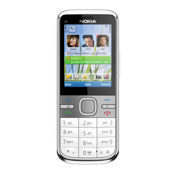
1–8 Table 4 Music ................................. 1–8 Table 5 Messaging ..............................1–9 Table 6 Power ................................ 1–9 List of Figures Figure 1 View of RM-645............................1–5 Issue 1 COMPANY CONFIDENTIAL Page 1 – 3 Copyright © 2010 Nokia. All rights reserved. - Page 16 RM-645 General Information (This page left intentionally blank.) Page 1 – 4 COMPANY CONFIDENTIAL Issue 1 Copyright © 2010 Nokia. All rights reserved.
-
Page 17: Product Selection
For GPRS/EGPRS networks, RM-645 is a Class B EGPRS MSC 32 (5 Rx + 3 Tx, max sum 6), which means a maximum upload speed of up to 298 kbit/s with EGPRS, and download speed of up to 178.8 kbit/s with GPRS. The device also supports Dual Transfer Mode (DTM) for simultaneous voice and packet data connection in GSM/EDGE networks;... -
Page 18: Product Features And Sales Package
• OTA provisioning & over the air SW update (FOTA) • Ovi Suite • Active Standby • Local/remote SyncML data sync • Web Browser (OSS), Java ™ MIDP 2.0, XHTML browsing over TCP/IP Messaging Page 1 – 6 COMPANY CONFIDENTIAL Issue 1 Copyright © 2010 Nokia. All rights reserved. -
Page 19: Product And Module List
• Voice commands, enhanced voice dialling (SIND) • Audio message reader for text messages and E-mail Add-on software framework • Symbian OS • Nokia Series 60, 3rd edition, feature pack 3.2 • Java: MIDP2.0 • C++ and Java SDKs Additional features •... -
Page 20: Mobile Enhancements
MU-41, 4 GB MU-43, 8 GB MU-44, 16 GB Connectivity cable CA-101D (inbox) Table 4 Music Enhancement Type Bluetooth speakers MD-7W (BT & plug-in) Mini speakers MD-9 Page 1 – 8 COMPANY CONFIDENTIAL Issue 1 Copyright © 2010 Nokia. All rights reserved. -
Page 21: Technical Specifications
EGSM900: 880 - 915 MHz GSM1800: 1710 - 1785 MHz GSM1900: 1850 - 1910 MHz WCDMA VIII (900): 880 - 915 MHz WCDMA I (2100): 1920 - 1980 MHz Issue 1 COMPANY CONFIDENTIAL Page 1 – 9 Copyright © 2010 Nokia. All rights reserved. -
Page 22: Environmental Conditions
Reduced performance Operational for shorts periods C...-15 only C...+70 Intermittent operation Operation not guaranteed but an C...-15 attempt to operate does not C...+85 damage the phone. Page 1 – 10 COMPANY CONFIDENTIAL Issue 1 Copyright © 2010 Nokia. All rights reserved. - Page 23 The standard for electrostatic discharge is IEC 61000-4-2, and this device fulfils level 4 requirements. RoHS This device uses RoHS compliant components and lead-free soldering process. Issue 1 COMPANY CONFIDENTIAL Page 1 – 11 Copyright © 2010 Nokia. All rights reserved.
- Page 24 RM-645 General Information (This page left intentionally blank.) Page 1 – 12 COMPANY CONFIDENTIAL Issue 1 Copyright © 2010 Nokia. All rights reserved.
- Page 25 Nokia Customer Care 2 — Service Tools and Service Concepts Issue 1 COMPANY CONFIDENTIAL Page 2 – 1 Copyright © 2010 Nokia. All rights reserved.
- Page 26 RM-645 Service Tools and Service Concepts (This page left intentionally blank.) Page 2 – 2 COMPANY CONFIDENTIAL Issue 1 Copyright © 2010 Nokia. All rights reserved.
-
Page 27: Table Of Contents
Figure 5 Module jig service concept ......................... 2–16 Figure 6 Service concept for RF testing and RF/BB tuning ................2–18 Figure 7 RF testing concept with RF coupler ....................2–19 Issue 1 COMPANY CONFIDENTIAL Page 2 – 3 Copyright © 2010 Nokia. All rights reserved. - Page 28 RM-645 Service Tools and Service Concepts (This page left intentionally blank.) Page 2 – 4 COMPANY CONFIDENTIAL Issue 1 Copyright © 2010 Nokia. All rights reserved.
-
Page 29: Service Tools
The table below gives a short overview of service devices that can be used for testing, error analysis, and repair of product RM-645. For the correct use of the service devices, and the best effort of workbench setup, please refer to various concepts. -
Page 30: General Tools
The table below gives a short overview of service devices that can be used for testing, error analysis, and repair of product RM-645. For the correct use of the service devices, and the best effort of workbench setup, please refer to various concepts. - Page 31 4 Connect an FBUS cable (if necessary). 5 Start Phoenix service software. Note: Phoenix enables CU-4 regulators via USB when it is started. Reconnecting the power supply requires a Phoenix restart. Issue 1 COMPANY CONFIDENTIAL Page 2 – 7 Copyright © 2010 Nokia. All rights reserved.
-
Page 32: Fps-21
In order to access the SD memory card slots inside FPS-21, the prommer needs to be opened by removing the front panel, rear panel and heatsink from the prommer body. Page 2 – 8 COMPANY CONFIDENTIAL Issue 1 Copyright © 2010 Nokia. All rights reserved. - Page 33 • Installation and warranty information SRT-6 Opening tool SRT-6 is used to open phone covers. Note: The SRT-6 is included in the Nokia Standard Toolkit. Issue 1 COMPANY CONFIDENTIAL Page 2 – 9 Copyright © 2010 Nokia. All rights reserved.
-
Page 34: Cables
The table below gives a short overview of service devices that can be used for testing, error analysis, and repair of product RM-645. For the correct use of the service devices, and the best effort of workbench setup, please refer to various concepts. -
Page 35: Ca-128Rs
Product-specific adapter cable for RF tuning. CA-31D USB cable The CA-31D USB cable is used to connect FPS-21 to a PC. It is included in the FPS-21 sales package. Issue 1 COMPANY CONFIDENTIAL Page 2 – 11 Copyright © 2010 Nokia. All rights reserved. -
Page 36: Ca-89Ds
Power cable The PCS-1 power cable (DC) is used with a docking station, a module jig or a control unit to supply a controlled voltage. Page 2 – 12 COMPANY CONFIDENTIAL Issue 1 Copyright © 2010 Nokia. All rights reserved. -
Page 37: Service Concepts
POS (Point of Sale) flash concept Figure 2 POS flash concept Type Description Product specific tools BL-5CT Battery Other tools FLS-5 POS flash dongle PC with Phoenix service software Issue 1 COMPANY CONFIDENTIAL Page 2 – 13 Copyright © 2010 Nokia. All rights reserved. -
Page 38: Flash Concept With Fps-21
Other devices FPS-21 Flash prommer box AC-35 Power supply PK-1 SW security device SS-46 Interface adapter PC with Phoenix service software Cables CA-89DS Service cable Page 2 – 14 COMPANY CONFIDENTIAL Issue 1 Copyright © 2010 Nokia. All rights reserved. -
Page 39: Table 6 Power
Power supply PK-1 SW security device SS-62 Flash adapter base SX-4 Smart card (for DCT-4 generation mobile device programming) PC with Phoenix service software Cables Issue 1 COMPANY CONFIDENTIAL Page 2 – 15 Copyright © 2010 Nokia. All rights reserved. -
Page 40: Module Jig Service Concept
Control unit FPS-21 Flash prommer box PK-1 SW security device SX-4 Smart card PC with VPOS and Phoenix service software Measurement equipment Cables CA-89DS Service cable Page 2 – 16 COMPANY CONFIDENTIAL Issue 1 Copyright © 2010 Nokia. All rights reserved. -
Page 41: Bb/Rf Tuning Concept With Module Jig
CU-4 Control unit PK-1 SW security device SX-4 Smart card PC with Phoenix service software Smart card reader Cables DAU-9S MBUS cable PCS-1 Power cable Issue 1 COMPANY CONFIDENTIAL Page 2 – 17 Copyright © 2010 Nokia. All rights reserved. -
Page 42: Bluetooth Testing Concept With
SX-4 Smart card SB-6 Bluetooth test and interface box Smart card reader PC with Phoenix service software Cables DAU-9S MBUS cable PCS-1 DC power cable Page 2 – 18 COMPANY CONFIDENTIAL Issue 1 Copyright © 2010 Nokia. All rights reserved. -
Page 43: Gps Testing Concept With Gps Rf Coupler
Smart card JXS-1 RF shield box PK-1 SW security device SS-62 Flash adapter base Smart card reader Measurement equipment PC with Phoenix service software Cables Issue 1 COMPANY CONFIDENTIAL Page 2 – 19 Copyright © 2010 Nokia. All rights reserved. - Page 44 Service Tools and Service Concepts Type Description CA-128RS RF service cable (product-specific adapter cable) PCS-1 Power cable DAU-9S MBUS cable XRS-6 RF cable 20dB attenuator Interface cable USB cable Page 2 – 20 COMPANY CONFIDENTIAL Issue 1 Copyright © 2010 Nokia. All rights reserved.
- Page 45 Nokia Customer Care 3 — BB Troubleshooting and Manual Tuning Guide Issue 1 COMPANY CONFIDENTIAL Page 3 – 1 Copyright © 2010 Nokia. All rights reserved.
- Page 46 RM-645 BB Troubleshooting and Manual Tuning Guide (This page left intentionally blank.) Page 3 – 2 COMPANY CONFIDENTIAL Issue 1 Copyright © 2010 Nokia. All rights reserved.
- Page 47 Bluetooth and FM radio troubleshooting ......................3–53 Bluetooth and FM radio introduction......................3–53 Bluetooth and FM radio component placement ..................3–54 Bluetooth and FM Radio Self Tests ......................3–55 Issue 1 COMPANY CONFIDENTIAL Page 3 – 3 Copyright © 2010 Nokia. All rights reserved.
- Page 48 Figure 20 GPS Quick Test window for GPS troubleshooting ................3–51 Figure 21 Key component placement for BTHFMRDS2.2D ................3–55 Figure 22 BT antenna............................3–55 Page 3 – 4 COMPANY CONFIDENTIAL Issue 1 Copyright © 2010 Nokia. All rights reserved.
-
Page 49: Baseband Self Tests In Phoenix
Always start the troubleshooting procedure by running the Phoenix self tests. If a test fails, please follow the diagram below. Dead or jammed device troubleshooting. If the phone is dead and you cannot perform the self tests, go to Issue 1 COMPANY CONFIDENTIAL Page 3 – 5 Copyright © 2010 Nokia. All rights reserved. - Page 50 RM-645 BB Troubleshooting and Manual Tuning Guide Troubleshooting flow Page 3 – 6 COMPANY CONFIDENTIAL Issue 1 Copyright © 2010 Nokia. All rights reserved.
-
Page 51: Power And Charging Troubleshooting
RM-645 BB Troubleshooting and Manual Tuning Guide Power and charging troubleshooting Dead or jammed device troubleshooting Troubleshooting flow - Page 1 of 2 Issue 1 COMPANY CONFIDENTIAL Page 3 – 7 Copyright © 2010 Nokia. All rights reserved. - Page 52 RM-645 BB Troubleshooting and Manual Tuning Guide Troubleshooting flow - Page 2 of 2 Page 3 – 8 COMPANY CONFIDENTIAL Issue 1 Copyright © 2010 Nokia. All rights reserved.
-
Page 53: Power Key Troubleshooting
RM-645 BB Troubleshooting and Manual Tuning Guide Power key troubleshooting Troubleshooting flow Issue 1 COMPANY CONFIDENTIAL Page 3 – 9 Copyright © 2010 Nokia. All rights reserved. -
Page 54: General Voltage Checking Troubleshooting
RM-645 BB Troubleshooting and Manual Tuning Guide General voltage checking troubleshooting Troubleshooting flow - Page 1 of 2 Page 3 – 10 COMPANY CONFIDENTIAL Issue 1 Copyright © 2010 Nokia. All rights reserved. - Page 55 RM-645 BB Troubleshooting and Manual Tuning Guide Troubleshooting flow - Page 2 of 2 Issue 1 COMPANY CONFIDENTIAL Page 3 – 11 Copyright © 2010 Nokia. All rights reserved.
-
Page 56: General Power Checking
Main user Notes Rename voltage Gazoo Memory, I/Os, display VSIM Gazoo 1.8/3.0 SIM card VAUX1 Gazoo Display VMEM Gazoo MicroSD Disabled in sleep VDIGMIC Gazoo Audio Page 3 – 12 COMPANY CONFIDENTIAL Issue 1 Copyright © 2010 Nokia. All rights reserved. -
Page 57: Charging Troubleshooting
RM-645 BB Troubleshooting and Manual Tuning Guide Charging troubleshooting Troubleshooting flow Issue 1 COMPANY CONFIDENTIAL Page 3 – 13 Copyright © 2010 Nokia. All rights reserved. -
Page 58: Usb Charging Troubleshooting
RM-645 BB Troubleshooting and Manual Tuning Guide USB charging troubleshooting Troubleshooting flow Page 3 – 14 COMPANY CONFIDENTIAL Issue 1 Copyright © 2010 Nokia. All rights reserved. -
Page 59: Battery Current Measuring Fault Troubleshooting
RM-645 BB Troubleshooting and Manual Tuning Guide Battery current measuring fault troubleshooting Troubleshooting flow Issue 1 COMPANY CONFIDENTIAL Page 3 – 15 Copyright © 2010 Nokia. All rights reserved. -
Page 60: Clocking Troubleshooting
RM-645 BB Troubleshooting and Manual Tuning Guide Clocking troubleshooting Troubleshooting flow Page 3 – 16 COMPANY CONFIDENTIAL Issue 1 Copyright © 2010 Nokia. All rights reserved. -
Page 61: Interface Troubleshooting
RM-645 BB Troubleshooting and Manual Tuning Guide Interface troubleshooting Flash programming fault troubleshooting Troubleshooting flow - Page 1 of 2 Issue 1 COMPANY CONFIDENTIAL Page 3 – 17 Copyright © 2010 Nokia. All rights reserved. - Page 62 BB Troubleshooting and Manual Tuning Guide Troubleshooting flow - Page 2 of 2 Figure 8 Flashing pic 1. Take single trig measurement for the rise of the BSI signal Page 3 – 18 COMPANY CONFIDENTIAL Issue 1 Copyright © 2010 Nokia. All rights reserved.
- Page 63 RM-645 BB Troubleshooting and Manual Tuning Guide Figure 9 Flashing pic 2. Take single trig measurement for the rise of the BSI signal Issue 1 COMPANY CONFIDENTIAL Page 3 – 19 Copyright © 2010 Nokia. All rights reserved.
-
Page 64: Sim Card Troubleshooting
RM-645 BB Troubleshooting and Manual Tuning Guide SIM card troubleshooting Troubleshooting flow Page 3 – 20 COMPANY CONFIDENTIAL Issue 1 Copyright © 2010 Nokia. All rights reserved. - Page 65 RM-645 BB Troubleshooting and Manual Tuning Guide Issue 1 COMPANY CONFIDENTIAL Page 3 – 21 Copyright © 2010 Nokia. All rights reserved.
-
Page 66: Microsd Card Troubleshooting
RM-645 BB Troubleshooting and Manual Tuning Guide MicroSD card troubleshooting Troubleshooting flow Page 3 – 22 COMPANY CONFIDENTIAL Issue 1 Copyright © 2010 Nokia. All rights reserved. -
Page 67: Usb Data Interface Troubleshooting
RM-645 BB Troubleshooting and Manual Tuning Guide USB data interface troubleshooting Troubleshooting flow - Page 1 of 2 Issue 1 COMPANY CONFIDENTIAL Page 3 – 23 Copyright © 2010 Nokia. All rights reserved. -
Page 68: User Interface Troubleshooting
• One or more keys are stuck, so that the key does not react when a keydome or a side key is pressed. This kind of failure is caused by mechanical reasons (dirt, rust, mechanical damage, etc.) Page 3 – 24 COMPANY CONFIDENTIAL Issue 1 Copyright © 2010 Nokia. All rights reserved. - Page 69 If the failure mode is not clear, start with the Keyboard test in Phoenix. In this phone the keyboard is connected to D2800 I/O pins. Troubleshooting flow Issue 1 COMPANY CONFIDENTIAL Page 3 – 25 Copyright © 2010 Nokia. All rights reserved.
-
Page 70: Keyboard Leds Troubleshooting
RM-645 BB Troubleshooting and Manual Tuning Guide Keyboard LEDs troubleshooting Troubleshooting flow Page 3 – 26 COMPANY CONFIDENTIAL Issue 1 Copyright © 2010 Nokia. All rights reserved. -
Page 71: Display Module Troubleshooting
Total Combined Not allowed. defect counts Two single dot defects that are within 5 mm of each other should be interpreted as combined dot defect. Issue 1 COMPANY CONFIDENTIAL Page 3 – 27 Copyright © 2010 Nokia. All rights reserved. - Page 72 APE ID). 3. Proceed to the display fault troubleshooting flowchart. Phoenix to find the detailed fault mode. Use the Display Test tool in Page 3 – 28 COMPANY CONFIDENTIAL Issue 1 Copyright © 2010 Nokia. All rights reserved.
-
Page 73: Display Fault Troubleshooting
RM-645 BB Troubleshooting and Manual Tuning Guide Display fault troubleshooting Troubleshooting flow Issue 1 COMPANY CONFIDENTIAL Page 3 – 29 Copyright © 2010 Nokia. All rights reserved. -
Page 74: Display Backlight Troubleshooting
When measuring with a single-ended probe each output is measured against the ground. The input signal for each loop test is single-ended. Page 3 – 30 COMPANY CONFIDENTIAL Issue 1 Copyright © 2010 Nokia. All rights reserved. - Page 75 HS_MIC HS_EAR_R and +21.3 and GND HS_EAR_L and AV mic to HP ear HS_MIC B2101 pad1 +18.2 and GND and GND B2101 pad2 and GND Issue 1 COMPANY CONFIDENTIAL Page 3 – 31 Copyright © 2010 Nokia. All rights reserved.
- Page 76 B2102 pad2 Measurement and GND data graphics B2103 pad1 below and GND B2103 pad2 and GND Measurement data Figure 10 AV_IN – HP_OUT, single-ended loop measurement Page 3 – 32 COMPANY CONFIDENTIAL Issue 1 Copyright © 2010 Nokia. All rights reserved.
- Page 77 BB Troubleshooting and Manual Tuning Guide Figure 11 AV_IN – IHF_L_OUT, single-ended loop measurement without filter Figure 12 AV_IN – AV_L _OUT, single-ended loop measurement Issue 1 COMPANY CONFIDENTIAL Page 3 – 33 Copyright © 2010 Nokia. All rights reserved.
-
Page 78: Internal Earpiece Troubleshooting
RM-645 BB Troubleshooting and Manual Tuning Guide Internal earpiece troubleshooting Troubleshooting flow Page 3 – 34 COMPANY CONFIDENTIAL Issue 1 Copyright © 2010 Nokia. All rights reserved. -
Page 79: Internal Microphone Troubleshooting
RM-645 BB Troubleshooting and Manual Tuning Guide Internal microphone troubleshooting Troubleshooting flow Issue 1 COMPANY CONFIDENTIAL Page 3 – 35 Copyright © 2010 Nokia. All rights reserved. -
Page 80: Internal Handsfree (Ihf) Troubleshooting
RM-645 BB Troubleshooting and Manual Tuning Guide Internal handsfree (IHF) troubleshooting Troubleshooting flow Page 3 – 36 COMPANY CONFIDENTIAL Issue 1 Copyright © 2010 Nokia. All rights reserved. -
Page 81: External Earpiece Troubleshooting
RM-645 BB Troubleshooting and Manual Tuning Guide External earpiece troubleshooting Troubleshooting flow Issue 1 COMPANY CONFIDENTIAL Page 3 – 37 Copyright © 2010 Nokia. All rights reserved. -
Page 82: External Microphone Troubleshooting
RM-645 BB Troubleshooting and Manual Tuning Guide External microphone troubleshooting Troubleshooting flow Page 3 – 38 COMPANY CONFIDENTIAL Issue 1 Copyright © 2010 Nokia. All rights reserved. -
Page 83: Acoustics Troubleshooting
The phone should be dry and clean, and no objects must be located in such a way that they close any of the holes. Issue 1 COMPANY CONFIDENTIAL Page 3 – 39 Copyright © 2010 Nokia. All rights reserved. -
Page 84: Earpiece Troubleshooting
RM-645 BB Troubleshooting and Manual Tuning Guide Earpiece troubleshooting Troubleshooting flow Page 3 – 40 COMPANY CONFIDENTIAL Issue 1 Copyright © 2010 Nokia. All rights reserved. -
Page 85: Ihf Troubleshooting
RM-645 BB Troubleshooting and Manual Tuning Guide IHF troubleshooting Troubleshooting flow Issue 1 COMPANY CONFIDENTIAL Page 3 – 41 Copyright © 2010 Nokia. All rights reserved. -
Page 86: Microphone Troubleshooting
RM-645 BB Troubleshooting and Manual Tuning Guide Microphone troubleshooting Troubleshooting flow Page 3 – 42 COMPANY CONFIDENTIAL Issue 1 Copyright © 2010 Nokia. All rights reserved. -
Page 87: Vibra Troubleshooting
BB Troubleshooting and Manual Tuning Guide Vibra troubleshooting Troubleshooting flow GPS troubleshooting GPS antenna The GPS antenna is located on the back side of the B-cover (left-hand side, upper corner). Issue 1 COMPANY CONFIDENTIAL Page 3 – 43 Copyright © 2010 Nokia. All rights reserved. - Page 88 RM-645 BB Troubleshooting and Manual Tuning Guide Figure 13 GPS antenna Page 3 – 44 COMPANY CONFIDENTIAL Issue 1 Copyright © 2010 Nokia. All rights reserved.
-
Page 89: Gps Layout And Basic Test Points
Use the following to test GPS using Phoenix. Steps 1. Start Phoenix service software. 2. From the File menu, select Scan Product and check that the correct product version is displayed. Issue 1 COMPANY CONFIDENTIAL Page 3 – 45 Copyright © 2010 Nokia. All rights reserved. - Page 90 On will turn on all the RF sections of the ASIC and so all LDOs will be present. Turning Receiver Action Note: These checks are part of GPS basic checks troubleshooting (page 3–52 ) Figure 15 GPS Control dialog box Page 3 – 46 COMPANY CONFIDENTIAL Issue 1 Copyright © 2010 Nokia. All rights reserved.
-
Page 91: Oscillator Test
Rx Control window, go to the Simple Tests section, select Oscillator Test and click Start. The Offset In the result will be returned and should be within the limits of +- 84Hz. Issue 1 COMPANY CONFIDENTIAL Page 3 – 47 Copyright © 2010 Nokia. All rights reserved. -
Page 92: Receiver Self Test
Oscillator test to prolong and result in Phoenix timing out. If you are carrying out both of these tests, run the Oscillator Test first, after which you can run the Receiver Self Test. Page 3 – 48 COMPANY CONFIDENTIAL Issue 1 Copyright © 2010 Nokia. All rights reserved. -
Page 93: Cw Test
GPS antenna test connector at a level of -110dBm and click Start. For Pin = -110dBm and negligible other losses, the expected result ranges are: • Galvanic 29.8dB to 38.1dB • Radiated 25.8dB to 38.1dB Issue 1 COMPANY CONFIDENTIAL Page 3 – 49 Copyright © 2010 Nokia. All rights reserved. -
Page 94: Quick Test Window
Oscillator Test . It does not necessarily mean that Oscillator Test has failed, but carrying out the Oscillator Test (page 3–47 ) Receiver Self Test (page 3–48 ) CW Test (page 3–49 ) individually will give more valid results. Page 3 – 50 COMPANY CONFIDENTIAL Issue 1 Copyright © 2010 Nokia. All rights reserved. -
Page 95: Gps Failure Troubleshooting
GPS troubleshooting is broken down into two parts: General GPS failure and GPS basic checks. The GPS failure troubleshooting flow can be followed and, where applicable, will feed into the basic checks troubleshooting flow. Issue 1 COMPANY CONFIDENTIAL Page 3 – 51 Copyright © 2010 Nokia. All rights reserved. - Page 96 RM-645 BB Troubleshooting and Manual Tuning Guide Troubleshooting flow Page 3 – 52 COMPANY CONFIDENTIAL Issue 1 Copyright © 2010 Nokia. All rights reserved.
-
Page 97: Gps Basic Checks Troubleshooting
The Bluetooth and FM radio are combined in the same ASIC, so both features are checked when troubleshooting. The following problems can occur with the Bluetooth and FM radio hardware: Issue 1 COMPANY CONFIDENTIAL Page 3 – 53 Copyright © 2010 Nokia. All rights reserved. -
Page 98: Bluetooth And Fm Radio Component Placement
FM audio through headset. Bluetooth and FM radio component placement The figure below shows the key component placement for BTHFMRDS2.2D in RM-645. Page 3 – 54 COMPANY CONFIDENTIAL Issue 1 Copyright © 2010 Nokia. All rights reserved. -
Page 99: Bluetooth And Fm Radio Self Tests
2. Start Phoenix service software. 3. Choose File → Scan Product. 4. From the Mode drop-down menu, set to Local. 5. Choose Testing → Self Tests. Issue 1 COMPANY CONFIDENTIAL Page 3 – 55 Copyright © 2010 Nokia. All rights reserved. - Page 100 JBT-9 or SB-6 Bluetooth test box (BT box) is required to perform a BER test. If a BT box is not available, Bluetooth functionality can be checked by transferring a file to another Bluetooth phone. Page 3 – 56 COMPANY CONFIDENTIAL Issue 1 Copyright © 2010 Nokia. All rights reserved.
- Page 101 RM-645 BB Troubleshooting and Manual Tuning Guide Bluetooth and FM radio module troubleshooting Troubleshooting flow Issue 1 COMPANY CONFIDENTIAL Page 3 – 57 Copyright © 2010 Nokia. All rights reserved.
- Page 102 Note: USB flashing does not work for a dead BB5 phone. • Create a request file. • Send the file to Nokia by e-mail. Use the following addresses depending on your location: • APAC: sydney.service@nokia.com • CHINA: repair.ams@nokia.com • E&A: salo.repair@nokia.com •...
- Page 103 Phone as Manufactured. To continue, click Start. Progress bars and messages on the screen show actions during phone programming, please wait. Issue 1 COMPANY CONFIDENTIAL Page 3 – 59 Copyright © 2010 Nokia. All rights reserved.
- Page 104 Phoenix , choose File → Scan Product . To connect the phone with ii Choose Tools → Certificate Restore . iii To choose a location for the request file, click Browse. Page 3 – 60 COMPANY CONFIDENTIAL Issue 1 Copyright © 2010 Nokia. All rights reserved.
- Page 105 Request file, click Start. To create the vi When the file for certificate restore has been created, send it to Nokia as an e-mail attachment. 3. Restore certificate. For this procedure, you must supply +12 V to CU-4 from an external power supply.
- Page 106 Next actions Phoenix tuning functions. After a successful rewrite, you must retune the phone completely by using Important: Perform all tunings: RF, BB, and UI. Page 3 – 62 COMPANY CONFIDENTIAL Issue 1 Copyright © 2010 Nokia. All rights reserved.
- Page 107 Write and/or repeat the procedure again. Energy Management Calibration window. 10. To end the procedure, close the Issue 1 COMPANY CONFIDENTIAL Page 3 – 63 Copyright © 2010 Nokia. All rights reserved.
- Page 108 RM-645 BB Troubleshooting and Manual Tuning Guide (This page left intentionally blank.) Page 3 – 64 COMPANY CONFIDENTIAL Issue 1 Copyright © 2010 Nokia. All rights reserved.
- Page 109 Nokia Customer Care 4 — RF Troubleshooting Issue 1 COMPANY CONFIDENTIAL Page 4 – 1 Copyright © 2010 Nokia. All rights reserved.
- Page 110 RM-645 RF Troubleshooting (This page left intentionally blank.) Page 4 – 2 COMPANY CONFIDENTIAL Issue 1 Copyright © 2010 Nokia. All rights reserved.
- Page 111 Figure 29 Typical readings ..........................4–17 Figure 30 Phoenix WCDMA Tx control window ....................4–20 Figure 31 Typical readings ..........................4–22 Figure 32 Antenna contacts ..........................4–24 Issue 1 COMPANY CONFIDENTIAL Page 4 – 3 Copyright © 2010 Nokia. All rights reserved.
- Page 112 RM-645 RF Troubleshooting (This page left intentionally blank.) Page 4 – 4 COMPANY CONFIDENTIAL Issue 1 Copyright © 2010 Nokia. All rights reserved.
-
Page 113: General Rf Troubleshooting
RF shielded environment, testing at frequencies of nearby base stations should be avoided. Level of repair The scope of this guideline is to verify functionality of the cellular RF block. Issue 1 COMPANY CONFIDENTIAL Page 4 – 5 Copyright © 2010 Nokia. All rights reserved. -
Page 114: Rf Key Components
RM-645 RF Troubleshooting RF key components Figure 23 RF key components Page 4 – 6 COMPANY CONFIDENTIAL Issue 1 Copyright © 2010 Nokia. All rights reserved. -
Page 115: Auto Tuning
3. Set the loss between CMU200 and the phone. (Total loss = cable + jig) 4. Go to auto tuning by selecting Tuning (Alt_U) → Auto-tune (Alt_A) from the menu. 5. Start auto tuning by clicking the Tune button. Issue 1 COMPANY CONFIDENTIAL Page 4 – 7 Copyright © 2010 Nokia. All rights reserved. -
Page 116: Self Test Troubleshooting
Self tests are recommended to be made when phone is in jig and a 50Ω load connected to the RF connector. Otherwise power tests may fail depending on antenna load Page 4 – 8 COMPANY CONFIDENTIAL Issue 1 Copyright © 2010 Nokia. All rights reserved. - Page 117 RM-645 RF Troubleshooting Troubleshooting flow Issue 1 COMPANY CONFIDENTIAL Page 4 – 9 Copyright © 2010 Nokia. All rights reserved.
-
Page 118: Receiver Troubleshooting
The reading should reflect the level of the signal generator (minus losses) ±5dB. When varying the level in the range -30 to -102dBm the reading should then follow within ±5dB. Page 4 – 10 COMPANY CONFIDENTIAL Issue 1 Copyright © 2010 Nokia. All rights reserved. -
Page 119: Gsm Receiver Troubleshooting Flowchart
RM-645 RF Troubleshooting GSM receiver troubleshooting flowchart Troubleshooting flow Issue 1 COMPANY CONFIDENTIAL Page 4 – 11 Copyright © 2010 Nokia. All rights reserved. -
Page 120: Wcdma Rx Chain Activation For Manual Measurement
If the settings are changed later on (for example, change of channel) you have to click Stop and Start again. Note: Clicking Stop also disables TX control if it was active. Page 4 – 12 COMPANY CONFIDENTIAL Issue 1 Copyright © 2010 Nokia. All rights reserved. -
Page 121: Wcdma Rssi Measurement
2. In the RX Power measurement window, select: • Mode: RSSI • Continuous mode 3. Click Start to perform the measurement. Note: WCDMA RSSI measurement is accurate only with WCDMA modulated signal. Issue 1 COMPANY CONFIDENTIAL Page 4 – 13 Copyright © 2010 Nokia. All rights reserved. -
Page 122: Wcdma Receiver Troubleshooting Flowchart
RM-645 RF Troubleshooting WCDMA receiver troubleshooting flowchart Troubleshooting flow Page 4 – 14 COMPANY CONFIDENTIAL Issue 1 Copyright © 2010 Nokia. All rights reserved. -
Page 123: Transmitter Troubleshooting
2. In Phoenix, select Testing → GSM → Rf Controls . The RF Controls window opens. Figure 28 Phoenix RF Controls window 3. Make the following settings: Issue 1 COMPANY CONFIDENTIAL Page 4 – 15 Copyright © 2010 Nokia. All rights reserved. - Page 124 Tx Power Level 4. Check the basic TX parameters, using a communication analyser (e.g. CMU200). • Power • Phase error • Modulation • Switching spectrum Page 4 – 16 COMPANY CONFIDENTIAL Issue 1 Copyright © 2010 Nokia. All rights reserved.
- Page 125 RM-645 RF Troubleshooting Figure 29 Typical readings 5. Change the power level in RF controls window and make sure the power reading follows accordingly. Issue 1 COMPANY CONFIDENTIAL Page 4 – 17 Copyright © 2010 Nokia. All rights reserved.
- Page 126 You can troubleshoot the GSM transmitter for each GSM band separately, one band at a time. If you want to troubleshoot GSM850, GSM1800 or GSM1900, change the band in the RF controls window and set the communication analyser accordingly. Page 4 – 18 COMPANY CONFIDENTIAL Issue 1 Copyright © 2010 Nokia. All rights reserved.
-
Page 127: Gsm Transmitter Troubleshooting Flowchart
RM-645 RF Troubleshooting GSM transmitter troubleshooting flowchart Troubleshooting flow Issue 1 COMPANY CONFIDENTIAL Page 4 – 19 Copyright © 2010 Nokia. All rights reserved. -
Page 128: Wcdma Transmitter Troubleshooting
WCDMA VIII 2788 4. Make the following general settings (the same values for all bands). Note that Max power limit is not checked by default. Page 4 – 20 COMPANY CONFIDENTIAL Issue 1 Copyright © 2010 Nokia. All rights reserved. - Page 129 If settings are changed (eg. new channel selected), you have to click RF Stop and Send again. 6. Check the basic TX parameters using a communication analyser (e.g. CMU200). Issue 1 COMPANY CONFIDENTIAL Page 4 – 21 Copyright © 2010 Nokia. All rights reserved.
- Page 130 RM-645 RF Troubleshooting Figure 31 Typical readings Page 4 – 22 COMPANY CONFIDENTIAL Issue 1 Copyright © 2010 Nokia. All rights reserved.
-
Page 131: Wcdma Transmitter Troubleshooting Flowchart
RM-645 RF Troubleshooting WCDMA transmitter troubleshooting flowchart Troubleshooting flow Issue 1 COMPANY CONFIDENTIAL Page 4 – 23 Copyright © 2010 Nokia. All rights reserved. -
Page 132: Antenna Troubleshooting
In the main antenna there is one feed and one GND contact. Check that GND and feed pads take proper contact to the pogo pin on the main PWB and the radiator flex. Figure 32 Antenna contacts Page 4 – 24 COMPANY CONFIDENTIAL Issue 1 Copyright © 2010 Nokia. All rights reserved. - Page 133 Nokia Customer Care 5 — Camera Module Troubleshooting Issue 1 COMPANY CONFIDENTIAL Page 5 – 1 Copyright © 2010 Nokia. All rights reserved.
- Page 134 RM-645 Camera Module Troubleshooting (This page left intentionally blank.) Page 5 – 2 COMPANY CONFIDENTIAL Issue 1 Copyright © 2010 Nokia. All rights reserved.
- Page 135 5–12 Secondary camera hardware troubleshooting ..................5–12 Secondary camera bad image quality troubleshooting................5–14 List of Figures Figure 33 Camera socket pin order........................5–8 Issue 1 COMPANY CONFIDENTIAL Page 5 – 3 Copyright © 2010 Nokia. All rights reserved.
- Page 136 RM-645 Camera Module Troubleshooting (This page left intentionally blank.) Page 5 – 4 COMPANY CONFIDENTIAL Issue 1 Copyright © 2010 Nokia. All rights reserved.
-
Page 137: Main (Back) Camera Troubleshooting
• The image may be blurred, though it does not show in the viewfinder • Analyse the picture from your PC monitor, full colour setting is recommended • If possible, compare with a picture of the same motive taken with a similar Nokia device Issue 1 COMPANY CONFIDENTIAL Page 5 –... -
Page 138: Main Camera Troubleshooting
RM-645 Camera Module Troubleshooting Main camera troubleshooting Troubleshooting flow Page 5 – 6 COMPANY CONFIDENTIAL Issue 1 Copyright © 2010 Nokia. All rights reserved. -
Page 139: Main Camera Baseband Troubleshooting
RM-645 Camera Module Troubleshooting Main camera baseband troubleshooting Troubleshooting flow Issue 1 COMPANY CONFIDENTIAL Page 5 – 7 Copyright © 2010 Nokia. All rights reserved. - Page 140 RM-645 Camera Module Troubleshooting Camera socket pin order Figure 33 Camera socket pin order Page 5 – 8 COMPANY CONFIDENTIAL Issue 1 Copyright © 2010 Nokia. All rights reserved.
-
Page 141: Main Camera No Recognizable Viewfinder Image Troubleshooting
RM-645 Camera Module Troubleshooting Main camera no recognizable viewfinder image troubleshooting Troubleshooting flow Issue 1 COMPANY CONFIDENTIAL Page 5 – 9 Copyright © 2010 Nokia. All rights reserved. -
Page 142: Main Camera Bad Image Quality Troubleshooting
RM-645 Camera Module Troubleshooting Main camera bad image quality troubleshooting Troubleshooting flow Page 5 – 10 COMPANY CONFIDENTIAL Issue 1 Copyright © 2010 Nokia. All rights reserved. -
Page 143: Camera Flash Troubleshooting
RM-645 Camera Module Troubleshooting Camera flash troubleshooting Context Note: Before checking flash functionality, make sure that the main camera is working ok. Troubleshooting flow Issue 1 COMPANY CONFIDENTIAL Page 5 – 11 Copyright © 2010 Nokia. All rights reserved. -
Page 144: Secondary (Front) Camera Troubleshooting
• The centre of the picture is sharper than the edges • If possible, compare with the picture on another Nokia device in a video call, and of the same motive Secondary camera hardware troubleshooting... - Page 145 RM-645 Camera Module Troubleshooting Issue 1 COMPANY CONFIDENTIAL Page 5 – 13 Copyright © 2010 Nokia. All rights reserved.
-
Page 146: Secondary Camera Bad Image Quality Troubleshooting
Phone must be in a video call for the front camera to be active. Note: Always use the "troubled" phone when evaluating a picture in a video call. Do not evaluate the picture on the receiving phone. Page 5 – 14 COMPANY CONFIDENTIAL Issue 1 Copyright © 2010 Nokia. All rights reserved. - Page 147 RM-645 Camera Module Troubleshooting Troubleshooting flow Issue 1 COMPANY CONFIDENTIAL Page 5 – 15 Copyright © 2010 Nokia. All rights reserved.
- Page 148 RM-645 Camera Module Troubleshooting (This page left intentionally blank.) Page 5 – 16 COMPANY CONFIDENTIAL Issue 1 Copyright © 2010 Nokia. All rights reserved.
- Page 149 Nokia Customer Care 6 — System Module Issue 1 COMPANY CONFIDENTIAL Page 6 – 1 Copyright © 2010 Nokia. All rights reserved.
- Page 150 RM-645 System Module (This page left intentionally blank.) Page 6 – 2 COMPANY CONFIDENTIAL Issue 1 Copyright © 2010 Nokia. All rights reserved.
- Page 151 Figure 39 MicroUSB connector .......................... 6–13 Figure 40 Display interface..........................6–14 Figure 41 Keyboard interface..........................6–15 Figure 42 Camera interface ..........................6–16 Figure 43 Audio interface ..........................6–17 Issue 1 COMPANY CONFIDENTIAL Page 6 – 3 Copyright © 2010 Nokia. All rights reserved.
- Page 152 RM-645 System Module Figure 44 Bluetooth interface ........................... 6–18 Figure 45 GPS interface............................6–19 Figure 46 FM radio interface ..........................6–19 Page 6 – 4 COMPANY CONFIDENTIAL Issue 1 Copyright © 2010 Nokia. All rights reserved.
-
Page 153: Introduction
Battery connector Tabby blade interface X2070 MicroSD connector X3200 Micro USB connector X3300 BTB connector Board-to-board connector X4400 RF connectors X6200 X7501 SIM connector X2700 Issue 1 COMPANY CONFIDENTIAL Page 6 – 5 Copyright © 2010 Nokia. All rights reserved. - Page 154 RM-645 System Module Key component placement Page 6 – 6 COMPANY CONFIDENTIAL Issue 1 Copyright © 2010 Nokia. All rights reserved.
- Page 155 RM-645 System Module System module block diagram Issue 1 COMPANY CONFIDENTIAL Page 6 – 7 Copyright © 2010 Nokia. All rights reserved.
-
Page 156: Energy Management
BSI line is used to recognize the battery capacity. This is done by means of an internal battery pull down resistor. Figure 34 Battery pin order Page 6 – 8 COMPANY CONFIDENTIAL Issue 1 Copyright © 2010 Nokia. All rights reserved. -
Page 157: Normal And Extreme Voltages
Sw shutdown In call Sw shutdown In idle Min Operating Voltage Vcoff+ 2.9 ± 0.1 Off to on Vcoff- 2.7 ± 0.1 On to off Issue 1 COMPANY CONFIDENTIAL Page 6 – 9 Copyright © 2010 Nokia. All rights reserved. -
Page 158: Power Key And System Power-Up
CLK600. The clock source is an internal RC oscillator in EM ASIC N2200 (during the power-up sequence) or RAPU SMPS Clk. Bluetooth uses a buffered and filtered 38.4MHz system clock from VCTCXO G7500. Page 6 – 10 COMPANY CONFIDENTIAL Issue 1 Copyright © 2010 Nokia. All rights reserved. -
Page 159: Power Distibution
RM-645 System Module Power distibution Figure 35 Power distribution diagram Issue 1 COMPANY CONFIDENTIAL Page 6 – 11 Copyright © 2010 Nokia. All rights reserved. -
Page 160: Sim Interface
EM ASIC and the microSD card. The microSD card connector is mounted on the main PWB. The µSD removal detection switch is inside the card sockect. Figure 37 MicroSD card interface Page 6 – 12 COMPANY CONFIDENTIAL Issue 1 Copyright © 2010 Nokia. All rights reserved. -
Page 161: Usb
Hot swap is supported, which means that USB devices may be plugged in and out at any time. MicroUSB connector This phone is provided with a specific connector for microUSB. Figure 39 MicroUSB connector Issue 1 COMPANY CONFIDENTIAL Page 6 – 13 Copyright © 2010 Nokia. All rights reserved. -
Page 162: User Interface
C4401 and C4402 added to PWB for improving the immunity to the device's own low band TX. RM-645 keyboard supports 3 keys multikeypress functionality. The LEDs at the UI mechanic assembly for main keyboard are controlled by EM ASIC. -
Page 163: Camera Interface
RAPU and controlled by the I2C bus, port 0. Both cameras are supplied by separate voltage regulators enabled by the camera software (GENIOs). Control signals to and from the camera flash driver are connected directly to RAPU (GENIOs). Issue 1 COMPANY CONFIDENTIAL Page 6 – 15 Copyright © 2010 Nokia. All rights reserved. -
Page 164: Audio Interface
RM-645 System Module Figure 42 Camera interface Audio interface The following block diagram illustrates the audio interface of the phone: Page 6 – 16 COMPANY CONFIDENTIAL Issue 1 Copyright © 2010 Nokia. All rights reserved. -
Page 165: Bluetooth Interface
BTHFM module. Bluetooth is physically integrated with FM radio in the BTHFM module ASIC, but from a functional point of view they have nothing in common Issue 1 COMPANY CONFIDENTIAL Page 6 – 17 Copyright © 2010 Nokia. All rights reserved. -
Page 166: Gps Interface
GPS interface The device includes an inbuilt GPS receiver and it works as a stand-alone positioning device. The GPS system is connected to RAPU ASIC. Page 6 – 18 COMPANY CONFIDENTIAL Issue 1 Copyright © 2010 Nokia. All rights reserved. -
Page 167: Fm Radio Interface
FM radio is physically integrated with Bluetooth in the BTHFM module ASIC, but from a functional point of view FM radio and Bluetooth have nothing in common. Figure 46 FM radio interface Issue 1 COMPANY CONFIDENTIAL Page 6 – 19 Copyright © 2010 Nokia. All rights reserved. -
Page 168: Rf Description
The transmitter functions are implemented in the RF ASIC. Even though the GSM and WCDMA signals are sent via different components, the principle of the transmission is the same. Page 6 – 20 COMPANY CONFIDENTIAL Issue 1 Copyright © 2010 Nokia. All rights reserved. - Page 169 RM-645 System Module Issue 1 COMPANY CONFIDENTIAL Page 6 – 21 Copyright © 2010 Nokia. All rights reserved.
-
Page 170: Frequency Mappings
RM-645 System Module Frequency mappings GSM850 frequencies Page 6 – 22 COMPANY CONFIDENTIAL Issue 1 Copyright © 2010 Nokia. All rights reserved. -
Page 171: Egsm900 Frequencies
RM-645 System Module EGSM900 frequencies Issue 1 COMPANY CONFIDENTIAL Page 6 – 23 Copyright © 2010 Nokia. All rights reserved. -
Page 172: Gsm1800 Frequencies
RM-645 System Module GSM1800 frequencies Page 6 – 24 COMPANY CONFIDENTIAL Issue 1 Copyright © 2010 Nokia. All rights reserved. -
Page 173: Gsm1900 Frequencies
RM-645 System Module GSM1900 frequencies Issue 1 COMPANY CONFIDENTIAL Page 6 – 25 Copyright © 2010 Nokia. All rights reserved. -
Page 174: Wcdma 2100 Rx Frequencies
RM-645 System Module WCDMA 2100 Rx frequencies Page 6 – 26 COMPANY CONFIDENTIAL Issue 1 Copyright © 2010 Nokia. All rights reserved. -
Page 175: Wcdma 2100 Tx Frequencies
RM-645 System Module WCDMA 2100 Tx frequencies Issue 1 COMPANY CONFIDENTIAL Page 6 – 27 Copyright © 2010 Nokia. All rights reserved. -
Page 176: Wcdma Viii (900) Frequencies
3732 2741 888,2 3552,8 2966 933,2 3732,8 2742 888,4 3553,6 2967 933,4 3733,6 2743 888,6 3554,4 2968 933,6 3734,4 2744 888,8 3555,2 2969 933,8 3735,2 Page 6 – 28 COMPANY CONFIDENTIAL Issue 1 Copyright © 2010 Nokia. All rights reserved. - Page 177 3760 2776 895,2 3580,8 3001 940,2 3760,8 2777 895,4 3581,6 3002 940,4 3761,6 2778 895,6 3582,4 3003 940,6 3762,4 2779 895,8 3583,2 3004 940,8 3763,2 Issue 1 COMPANY CONFIDENTIAL Page 6 – 29 Copyright © 2010 Nokia. All rights reserved.
- Page 178 3788 2811 902,2 3608,8 3036 947,2 3788,8 2812 902,4 3609,6 3037 947,4 3789,6 2813 902,6 3610,4 3038 947,6 3790,4 2814 902,8 3611,2 3039 947,8 3791,2 Page 6 – 30 COMPANY CONFIDENTIAL Issue 1 Copyright © 2010 Nokia. All rights reserved.
- Page 179 3816 2846 909,2 3636,8 3071 954,2 3816,8 2847 909,4 3637,6 3072 954,4 3817,6 2848 909,6 3638,4 3073 954,6 3818,4 2849 909,8 3639,2 3074 954,8 3819,2 Issue 1 COMPANY CONFIDENTIAL Page 6 – 31 Copyright © 2010 Nokia. All rights reserved.
- Page 180 3084 956,8 3827,2 2860 3648 3085 3828 2861 912,2 3648,8 3086 957,2 3828,8 2862 912,4 3649,6 3087 957,4 3829,6 2863 912,6 3650,4 3088 957,6 3830,4 Page 6 – 32 COMPANY CONFIDENTIAL Issue 1 Copyright © 2010 Nokia. All rights reserved.
- Page 181 Nokia Customer Care Glossary Issue 1 COMPANY CONFIDENTIAL Page Glossary– 1 Copyright © 2010 Nokia. All rights reserved.
- Page 182 RM-645 Glossary (This page left intentionally blank.) Page Glossary– 2 COMPANY CONFIDENTIAL Issue 1 Copyright © 2010 Nokia. All rights reserved.
- Page 183 Clock Timing Sleep and interrupt block of Tiku Continuous wave D/A-converter Digital-to-analogue converter Digital-to-analogue converter Digital Battery Interface DBus DSP controlled serial bus connected between UPP_WD2 and Helgo Issue 1 COMPANY CONFIDENTIAL Page Glossary– 3 Copyright © 2010 Nokia. All rights reserved.
- Page 184 High speed circuit switched data (data transmission connection faster than GSM) Hardware Input/Output IBAT Battery current Integrated circuit ICHAR Charger current Interface Integrated hands free IMEI International Mobile Equipment Identity Page Glossary– 4 COMPANY CONFIDENTIAL Issue 1 Copyright © 2010 Nokia. All rights reserved.
- Page 185 Software tool of DCT4.x and BB5 Personal Information Management Phase locked loop (Phone) Permanent memory General Purpose IO (PIO), USARTS and Pulse Width Modulators PURX Power-up reset Printed Wiring Board Issue 1 COMPANY CONFIDENTIAL Page Glossary– 5 Copyright © 2010 Nokia. All rights reserved.
- Page 186 Universal Energy Management chip (Enhanced version) UEMEK See UEME User Interface UPnP Universal Plug and Play Universal Phone Processor UPP_WD2 Communicator version of DCT4 system ASIC Page Glossary– 6 COMPANY CONFIDENTIAL Issue 1 Copyright © 2010 Nokia. All rights reserved.
- Page 187 Wideband code division multiple access Watchdog WLAN Wireless local area network XHTML Extensible hypertext markup language Zocus Current sensor (used to monitor the current flow to and from the battery) Issue 1 COMPANY CONFIDENTIAL Page Glossary– 7 Copyright © 2010 Nokia. All rights reserved.
- Page 188 RM-645 Glossary (This page left intentionally blank.) Page Glossary– 8 COMPANY CONFIDENTIAL Issue 1 Copyright © 2010 Nokia. All rights reserved.
- Page 189 www.s-manuals.com...