
Related Manuals for Storz DUOLITH SD1


Summary of Contents for Storz DUOLITH SD1
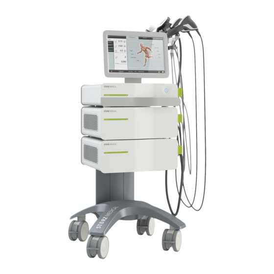
- Page 1 DUOLITH SD1 Tower ® BT.#### Part No. 19900.xxxx Published: March 2020 Original language: German Manufacturer / Publisher: STORZ MEDICAL AG Lohstampfestr. 8 CH-8274 Tägerwilen Switzerland 29081.0002...
- Page 2 17 360 02 0320...
- Page 3 Impressum Operating manual for DUOLITH SD1 Tower ® Manufacturer STORZ MEDICAL AG Lohstampfestrasse 8 CH-8274 Tägerwilen Telephone: +41 (0)71 677 45 87 Fax: +41 (0)71 677 45 09 E-mail: service@storzmedical.com URL: www.storzmedical.com Medical devices identified with this CE mark are in accordance with the regulations in EC Directive 93/42/EEC "Council Directive concerning medical devices".
- Page 4 Structure of the operating manual This operating manual contains all the information required for operating the DUOLITH ® SD1 Tower manufactured by STORZ MEDICAL AG. All safety information is provided in C hapter eneral safety infOrMatiOn contains the list of indications and contraindications as well as the...
- Page 5 Warning notes This manual contains warnings, safety instructions and specific operating instructions in accordance with liability regulations. DANGER refers to a situation of acute danger which, if not avoided, could lead to serious or fatal injury. DANGER! The source of the danger is stated here. These are the possible consequences! •...
- Page 6 Instructions for actions • This text instructs you in how to operate your system correctly. – This text subdivides an action into steps or comments on the action step. h This text shows the result of an action. Lists – This text is part of a list. Menus and buttons Names of menus and buttons are highlighted by being written in CAPITAL LETTERS.
-
Page 7: Table Of Contents
Table of Contents General Safety Information Instructions for safe use 1.1.1 Intended use and operational safety . . 1-2 1.1.2 Safety during treatment of the patient. . 1-5 Warning against damage to equipment and the device Principles Physical principles 2.1.1 Indications . - Page 8 Description of the R-SW module with accessories 3-19 3.7.1 Control and functional elements . 3-19 3.7.1.1 Compatible handpieces . . 3-20 3.7.2 R-SW handpiece . . 3-20 3.7.3 V-ACTOR handpiece . . 3-21 3.7.4 Connecting handpieces . . 3-22 3.7.5 Connecting VACU-ACTOR .
- Page 9 4.5.18 Connecting an external display . . 4-29 4.5.19 Saving image data with DICOM. . 4-29 4.5.19.1 DICOM configuration . . 4-29 4.5.19.2 DICOM Worklist . . 4-30 4.5.19.3 Saving/printing DICOM . . 4-30 4.5.20 Data transfer via the GDT interface. .
- Page 10 Cleaning, Maintenance, Overhaul General information about cleaning Modul F-SW 6.2.1 Cleaning the F-SW handpieces . . 6-3 6.2.2 Water renewal . . 6-3 6.2.2.1 Draining the water circuit . 6-4 6.2.2.2 Filling the water circuit . 6-5 Modul R-SW 6.3.1 Cleaning the R-SW handpieces .
- Page 11 Warranty and service Warranty for the DUOLITH ® Warranty of the handpieces Warranty for the VACU-ACTOR Service Ultrasound (optional) 10-1 10.1 Connecting the ultrasound probe 10-2 10.2 Switching on the ultrasound module 10-3 10.3 Foot switch 10-4 10.4 Operating Manual Telemed Ultrasound device 10-4 17 360 02 0320...
- Page 12 17 360 02 0320...
-
Page 13: General Safety Information
General Safety Information... -
Page 14: Instructions For Safe Use
The device is only allowed to be used for the applications described in C 2.1.1 hapter ndiCatiOns • Only perform treatments approved by STORZ MEDICAL AG! Furthermore, the device is only allowed to be operated by trained personnel who comply with the p in C 2.2. - Page 15 Do not reconnect them until they have been completely reassembled! • The optional KARL STORZ foot switch must not be used in potentially explosive atmospheres according to classification AP as per IEC 60601. Protection against high voltage Very high voltages are generated in the F-SW module when operating the device.
- Page 16 – Washing ether – Petrol ether The optional KARL STORZ foot switch must not be used in potentially explosive atmospheres according to classification AP as per IEC 60601. Protection against noise The noise level during administration of shock waves is within the safe area.
-
Page 17: Safety During Treatment Of The Patient
The patient should not be under anaesthesia. Only perform treatments approved by STORZ MEDICAL AG! The user is responsible for correctly positioning the handpieces and suction cup and correctly selecting the treatment zone. - Page 18 The separate operating manuals for all devices used in conjunction with the DUOLITH SD1 (localisation systems, ECG devices, etc.) must be viewed as part of ® the complete operating manual. Always comply with all the information contained therein. The system must only be connected to properly earthed and correctly installed shockproof sockets! Set-up and operation There are ventilation slits on the side of the device which must not be covered by...
-
Page 19: Principles
Principles... -
Page 20: Physical Principles
Physical principles The DUOLITH ® SD1 is a universal, modular shock wave generator that can be used either for treatment involving medium- to high-energy electromagnetically generated shock waves or low-energy pneumatically generated shock waves. This multifunctionality is achieved by using different shock wave modules which deliver two types of shock wave: focused shock waves –... -
Page 21: Indications
2.1.1 Indications Orthopaedics / Pain Therapy – Plantar fasciitis / heel spur / heel pain / calcaneal spur – Trigger Point Therapy – Treatment of deep muscle trigger points – Treatment of superficial muscle trigger points – Myofascial pain syndrome / Myofascial trigger points* / Acupuncture points –... -
Page 22: Contraindications
– Spastic muscle paralyses (caused by infantile cerebral palsy or stroke for exam- ple) * A sound knowledge of trigger point therapy and trigger point shock wave therapy (TrST) is required for therapeutic application of the DUOLITH SD1 in the field of trigger point shock wave therapy. 2.1.2 Contraindications... -
Page 23: Preconditions For Operation
An introduction to the principles of operation will be provided by your STORZ MEDICAL dealer with reference to this operating manual and will be documented in the system logbook. - Page 24 empty page 17 362 02 0320...
-
Page 25: System Description
System Description... -
Page 26: Overview Of The Entire System
Overview of the entire system The concept of the DUOLITH ® SD1 device is modular. Depending on its level of expansion, the device includes the following modules: 1 CONTROL module with touch screen 1.1 CONTROL module with integrated ultrasound unit* 2 R-SW module 3 F-SW module Fig. - Page 27 1 Monitor 2 CONTROL module 3 Master switch 4 F-SW module 5 R-SW module 6 Mains connector with mains fuse holder 7 Voltage selector switch 8 Potential equalisation 9 Transport handle 10 Handpiece holder Fig. 3-2 Rear complete 17 363 02 0320...
-
Page 28: Scope Of Supply
Scope of supply The Duolith is available in the following expansion levels: Expansion level Standard accessories – R-SW handpiece set – R-SW shock transmitters – VACU-ACTOR start kit – Mains cables – Gel bottle – User manual (operating manual, system logbook) Trolley &... - Page 29 Expansion level Standard accessories – Ultrasound probe 9 MHz – F-SW handpiece set – R-SW handpiece set – R-SW shock transmitters – VACU-ACTOR start kit – Mains cables – Gel bottle – Silicone oil bottle – Water bag Trolley & CONTROL module with integrated ultrasound unit &...
-
Page 30: Unpacking The Device
3.2.1 Unpacking the device • Check that all items are included in the packaging container and that they are not damaged. • Carefully remove the devices and accessories from the packaging container. • Contact your supplier or the manufacturer/dealer immediately if any items are missing or damaged. - Page 31 The handpiece holder is fixed in place on the device with a clamping screw and can be height-adjusted. To mount the handpiece holder • Slide the end of the holding rod into the opening on the device column. Fig. 3-4 Opening for the holding rod Fig.
-
Page 32: Electrical Connection
3.3.3 Potential equalisation connection The DUOLITH SD1 features a potential equalisation connection. ® • Connect one end of the potential equalisation cable to the PE connection on the DUOLITH ® SD1 and the other end to your PE connection. Fig. 3-7 Potential equalisation connection 3.3.4 Electrical connection The device can be operated on a mains voltage of 230 V or 115 V. -
Page 33: Transport
Changing the mains voltage • Move the switch using a pointed object (such as a flat-blade screwdriver) until the required value is under the arrowhead. Fig. 3-9 Mains voltage set to 115 V • Adjust the fuse value of the mains fuse according to the selected mains voltage (see c 6.5 f hapter... - Page 34 • Push the rod of the handpiece holder down. • Turn the handpiece holder inward. Fig. 3-11 Handpiece holder during transport • Release the brake on the transport wheels by pressing lightly from below. 3-10 Fig. 3-12 Releasing the wheels •...
-
Page 35: Description Of The Control Module
Fig. 3-14 Positioning handle • Lock the transport wheels once again. Description of the Control module 3.5.1 Control and functional elements The individual modules of the device are operated using the control module by means of a colour TFT LCD monitor with touch screen. The control module has a standby on/off switch with a check lamp (Fig. -
Page 36: Connectors
3.5.2 Connectors 2 3 4 5 1 HDMI 2 USB1 3 USB2 4 USB3 (2.0) 5 Audio 6 LAN Fig. 3-16 Rear side - connectors control module Connectors Control module The USB connectors serve as an interface for data input and output. •... -
Page 37: Description Of The F-Sw Module With Accessories
Description of the F-SW module with accessories The F-SW module generates focused shock waves with a short wavelength that are concentrated on a focal zone outside the therapy head. They take effect at depth. The penetration depth can be varied using stand-off devices, and be adapted to the tissue level which is to be treated. -
Page 38: F-Sw Handpiece
3.6.3 F-SW handpiece The F-SW handpiece makes it possible to mechanically adjust the therapeutic penetration depth. This is possible by using an additional stand-off device. Refer to the application brochure for more details about treatment. Fig. 3-20 F-SW handpiece without stand-off device with stand-off device I (short) with stand-off device II (long) for 50 mm depth of focal... -
Page 39: F-Sw Sepia Handpiece
3.6.4 F-SW SEPIA handpiece Focused shock waves that are concentrated on a focal zone outside the handpiece are administered over the F-SW handpiece into the body at the treatment zone. 1 Display 2 Trigger button 3 Clamping ring 4 Fixing screws 5 Coupling diaphragm 6 Color ring Fig. -
Page 40: C-Actor Ii Handpiece
3.6.5 C-ACTOR II handpiece The C-ACTOR ll handpiece can be operated as an optional accessory for the Duolith and Cellactor device lines, on both the T-Top and Tower versions. Use of this handpiece enables acoustic wave treatment to be performed with greater efficiency than with the C-ACTOR handpiece. -
Page 41: F-Sw Sepia / C-Actor Sepia Handpiece
3.6.6 F-SW SEPIA / C-ACTOR SEPIA handpiece The DUOLITH SD1 can be controlled directly via the handpiece. Corresponding setting buttons can be used for selecting the treatment parameters. 1 Reduce energy 2 Increase energy 3 Reduce frequency 4 Increase frequency 5 Menu / Input / reverse display (press >3 sec) -
Page 42: Handpiece Connection
3.6.7 Handpiece connection • Connect the plug of the handpiece into the connector on the right of the F-SW module. 1 Locking screw 2 Hybrid Connector • a n Fig. 3-27 Connecting the handpiece • Secure it using the locking screw. The locking screw must be tightened up to the stop until finger-tight. - Page 43 If the device is equipped with the CONTROL module, it is operated using the touch screen. 1 Touch screen 2 Checklamp 3-19 3 R-SW module Fig. 3-28 Front of R-SW module with CONTROL 1 Mains switch 2 R-SW module Fig. 3-29 Rear side of the DUOLITH SD1 17 363 02 0320...
-
Page 44: R-Sw Handpiece
3.7.1.1 Compatible handpieces The following handpieces are allowed to be connected to the R-SW module: – R-SW handpiece Art. no. 21700.1001 – V-ACTOR II Art. no. 19365.0001 – V-ACTOR II HF Art. no. 19365.1001 3.7.2 R-SW handpiece Radial, low-energy shock waves (R-SW) are administered into the body by means of a freely movable handpiece, and encompass the entire pain zone. -
Page 45: V-Actor Handpiece
The R-SW handpiece is also updated immediately after it is connected when there has been a software update of the system. Depending on the therapy to be performed, the handpiece can be equipped with dif- ferent shock transmitters: For operation of the handpiece R-SW using the embedded display, using the shock transmitters as well as changing the shock transmitters please read the separate pera... -
Page 46: Connecting Handpieces
3.7.4 Connecting handpieces The R-SW module has four connectors. These are located on the right side of the device. VACU-ACTOR connection 2 u. 3 Connection for R-SW handpieces Connection for V-ACTOR handpiece Fig. 3-33 Connection for the handpieces and the VACU-ACTOR •... -
Page 47: Connecting Vacu-Actor
3.7.5 Connecting VACU-ACTOR 1 Coupling silicone hose 2 Hose 3 Coupling for connection the suction cup 4 Suction cup 5 Bacteria filter size relationships are not real Fig. 3-35 Connection VACU-ACTOR NOTE Immediately after the device output a one-sterile filter is used to avoid contamina- tion of the device and to protect the following patients against comtamination. -
Page 48: Connecting The Foot Switch
US image); the image on the display can be traversed again once the foot switch is released. Treatment with the VACU-ACTOR can be activated and deactivated with the aid of the foot switch. Fig. 3-37 Optional Karl Storz foot switch 3-24 17 363 02 0320... -
Page 49: Operation
Operation... -
Page 50: Switching On
Read C before beginning treatment. hapter eneral afety nfOrMatiOn Switching on • Switch the device on using the main switch on the back of the column (Fig. 4-1). • Press the Standby button on the CONTROL module. Fig. 4-1 Mains switch Standby button –... -
Page 51: Operating The Device Over The Handpiece
Operating the device over the handpiece In its basic configuration, the DUOLITH ® SD1 consists of the trolley, a R-SW module and/or a F-SW module and the corresponding handpieces. This configuration of devices can be controlled directly using the handpiece when using R-SW or F-SW SEPIA handpiece. -
Page 52: Displays And Symbols
Displays and symbols The DUOLITH ® SD1 is operated using a colour TFT LCD monitor with touch screen function and graphical user interface. The user interface of the DUOLITH SD1 is divided into various areas for displaying ® different information. Menu bar: Monitor Monitor Counter... -
Page 53: Module Selection
4.4.1 Module selection The field at the top left is used for displaying the operating modes that can be select- ed. Once a module is connected, it is possible to activate the corresponding operating mode in the module selection area. The active module button is highlighted. Fig. -
Page 54: Parameter Selection And Counter Readings
4.4.2 Parameter selection and counter readings Operating mode R-SW and F-SW parameter selection The PARAMETER SELECTION field is used for displaying and setting the treatment parameters. This is where you define the energy level as well as the number and fre- quency of the pulses before each treatment. - Page 55 Symbols Meaning Display of the number of pulses administered Press the Reset button to set the display to 0. Display of the energy output per F-SW treatment Table 4-3 Counter readings Operating mode VACU-ACTOR Fig. 4-8 Setting parameters- operating mode VACU-ACTOR Symbols Meaning Set intensity:...
-
Page 56: Contact Intensity And Skin Touch Display
Treatment OFF. Press to start treatment. Treatment ON. Press to stop treatment. Table 4-4 Setting parameters VACU ACTOR Explanation of terms Mode VI The suction cup creates an interaction of vacuum and positive pressure with the adju- sted frequency. Mode VC The suction cup creates a negative pressure. - Page 57 Symbols Meaning Display of the contact intensity from yellow to green (optimum pressure). Skin Touch ON: the R-SW shocks are triggered without activating the trigger button by simply pressing the shock transmitter to the treatment zone. Skin Touch OFF: the R-SW shocks are triggered only when the trigger button is activated.
- Page 58 4.4.4 Treatment menu bar Use the TREATMENT menu bar to call up stored treatment parameters and treat- ment reports as indications. Fig. 4-10 Treatment menu bar Buttons Meaning The ANATOMY view appears automatically when the Markers for various treatment zones device is started.
-
Page 59: Device Info And Settings Menu Bar
4.4.5 Device info and settings menu bar The bottom navigation bar contains control buttons used for navigating through the menus: – Touch calibration – Software update – Options – Service – Filling the water circuit – Draining the water circuit –... -
Page 60: Touch Screen Operation
Touch Screen operation 4.5.1 Password protection It is possible to protect your SMAG display with a password. If starting the display anew or if it is in screen saver mode so the display is locked and can only be unlocked by entering the password. Activate password protection •... - Page 61 Deactivate password protection • Press several seconds on date and time field • Press to deactivate password entry (the check mark needs to be can- celled after that). • Type now your password on the following screen. • Confirm with h Your password is deactivated.
-
Page 62: Setting Brightness And Volume
4.5.2 Setting brightness and volume • Press • In the opened menu list press • Tap on the scale at the desired position in order to adjust the brightness of the screen or the volume. • Press to save the settings. If the menu is exited without saving the changes, the presettings will be reloaded. -
Page 63: Selecting Treatment Parameters
4.5.4 Selecting treatment parameters You can set the treatment parameters manually or load a predefined indication. For manual selection • Set the energy level as well as the number and frequency of the pulses using the buttons in the PARAMETER SELECTION field. h The treatment is now carried out with the displayed values. - Page 64 To load only the indications for a particular treatment zone • Press the marker for the treatment zone. Fig. 4-16 Selectable treatment zones – The alphabetically sorted list of indications for this treatment zone is opened. Navigating in the list 4-16 Use the navigation bar on the right edge of the display to move within the list.
- Page 65 Calling up detailed views For increased clarity, you can call up magnified views of the treatment photos as well as the recommended shock transmitters and stand-off devices. • Press the corresponding treatment photo. – The display shows a magnified view of the picture. Fig.
-
Page 66: Saving Indications
Fig. 4-19 Patient dataset has been loaded The treatment now takes place with the loaded parameters and is recorded in the patient data as a treatment report. buttons can be used to switch back and forth between the indication and the patient dataset. More information about the patient record can be found in C 4.5.10 p hapter... -
Page 67: Copying Indications
NOTE An empty indication without any entryof a treatment step will not be saved. Your indication is now created in the system. If you press the button to return to the overview, you will see your new indication in the list. 4.5.7 Copying indications A copy of a preprogrammed indication can also be created. -
Page 68: Storing Treatment Notes
Fig. 4-21 New indication in editing mode You can now: – Store treatment notes – Load treatment images – Define treatment steps 4.5.9.1 Storing treatment notes • To add remarks to the indication, press in the line. Using the onscreen keypad, you can now enter your remarks and notes in the text box. •... -
Page 69: Creating, Deleting Or Editing Treatment Steps
Newly loaded pictures and videos are automatically labelled with the date and time. If you select the picture or video, you can have the picture caption displayed in the text box under the picture bar. Fig. 4-23 New image or video •... -
Page 70: Patient Treatment Report
Deleting a treatment step • Open the treatment step by pressing • Press to activate editing mode. DELETE STEP. • Press • Confirm your input by pressing 4.5.10 Patient treatment report Each treatment of a patient can be recorded in a treatment report and stored. 4.5.10.1 Loading patient data •... - Page 71 Fig. 4-26 Patient data • In the TREATMENTS line, press the button to call up details. – You can now see which parameters have been used for the patient’s treatment. 4-23 Fig. 4-27 Treatment parameters used 17 364 02 0320...
-
Page 72: Editing Patient Data
4.5.10.2 Editing patient data You can add additional notes or treatment pictures by setting the dataset to editing mode. • Press the button to do this. The buttons with the pencil icon indicate the areas that can be edited. You can now: –... -
Page 73: Exporting Treatment Data
Fig. 4-29 Creating a new patient • Enter the data. • Save the entry by pressing • You can edit your new patient dataset to – Store notes – Add treatment pictures For information about this, read C 4.5.9.1 s hapter tOring treatMent nOtes and C... -
Page 74: Deleting Patient Datasets
NOTE If you only want to export treatment data of a patient - without his personal data - select «OPTIONS» «DATA EXPORT ANONYMOUS» before exporting. 4.5.13 Deleting patient datasets • Open the patient record to be deleted. • Press – The dataset is set to editing mode. •... -
Page 75: Software Updates
4.5.16 Software updates NOTE If you have saved the specific presettings for your ultrasound probe in the system, note them down before the software update and then reenter them once again after the update. • Connect the USB stick to the left slot (USB-A, see C 3.1 C hapter OntrOl and funCtiO... -
Page 76: Changing Software Settings
4.5.17 Changing software settings This function enables you to activate or deactivate indication groups. • Press • In the open menu list, select the function. Fig. 4-31 Options: Orthopaedics active 4-28 You see the list of possible indication groups. symbol before an indication group indicates that it is activated. •... -
Page 77: Connecting An External Display
In order to be able to configure DICOM, you will need a DICOM Upgrade Kit. Please contact your dealer. The DICOM configuration of the DUOLITH SD1 is accomplished via SETTINGS -> OPTIONS -> DICOM. You obtain the DICOM access data from your DICOM Administrator. -
Page 78: Dicom Worklist
4.5.19.2 DICOM Worklist If a Worklist server is configured on your DUOLITH SD1, then you can call up the active entries via 4.5.19.3 Saving/printing DICOM If a Store/Print server is configured on your DUOLITH SD1, then you can use the Store... -
Page 79: Sending/Receiving Data Or Requests Via Gdt
Sending/receiving data or requests via GDT • To start the ‘GDT request’, press 4-31 The DUOLITH SD1 reads in the patient data that were previously made available by the doctor’s surgery system. Fig. 4-35 GDT request 17 364 02 0320... -
Page 80: Visible Body - Anatomy Atlas
• To send the data of the doctor’s surgery EDP system, press The DUOLITH SD1 sends the supplemented data back to the doctor’s surgery system. Fig. 4-36 GDT transfer 4.5.21 Visible Body - Anatomy Atlas 4-32 Visible Body is an interactive 3D atlas of the human body allowing all 3D models and animations of the body systems and regions of humans to be represented. -
Page 81: Starting Visible Body
4.5.21.1 Starting Visible Body • To start the Anatomy Atlas, press Fig. 4-37 Visible Body - home screen After starting Visible Body always the menu item is opened. 4-33 Fig. 4-38 Menu - selection of the muscle regions 17 364 02 0320... -
Page 82: Submenu
• To get further regions slide your fingers across the touchscreen from bottom to top or back. This is also valid for the other menu items. Available menu items: – Regions – Systems – Cross Sections – Senses – Muscle Actions 4.5.21.2 Submenu •... - Page 83 Symbol Name Integumentary Skeletal Nervous Circulatory Respiratory Muscular Digestive Urinary Lymphatic Endocrine Reproductive 4-35 Table 4-8 Toolbar - left column in the submenu The illustrations can be moved to the right, left, up and down. They can be enlarged or reduced as well by spreading with two fingers and they can be turned by touching with one finger.
-
Page 84: Marking Treatment Regions
Detail view with info text You can select individual skeletal, muscular, nervous and other body parts by touching it in the detail view. • Press the desired body part on the touch screen. – The desired body part will be colored blue. –... -
Page 85: Settings
Fig. 4-41 Visible Body - with marked region • Press the symbol to create a screenshot. – It will be saved automatically under the currently opened patient data. 4.5.21.4 Settings 4-37 Press the symbol to open the settings. The symbol can be found either in the lower right or the upper right corner of the touch screen. -
Page 86: Exiting Visible Body
Fig. 4-43 Window - language selection • Press the desired language. • Press on the lower right corner of the language selection window. • Now press at any area outside the settings area to switch back to menu. 4.5.21.5 Exiting Visible Body •... -
Page 87: Operation With The Module F-Sw
Operation with the Module F-SW • Switch on the device as described in C 4.1 s hapter WitChing On • On the display, select the button in the ‘Module selection’ field (optionally, the button). h The selected module is activated. WARNUNG ! If there are malfunction of the device or its components Various injuries are possible! -
Page 88: Setting Treatment Parameters
Fig. 4-44 Trigger button of the F-SW SEPIA handpiece h The HV test has been performed successfully. The display of energy levels in the SHOCK WAVE PARAMETERS function field is now active. You can now select the shock wave parameters for treatment. NOTE A corresponding fault message appears on the display if the system detects a malfunction during the test. - Page 89 F-SW Energy flux density in mJ/mm Maximum frequency F-SW module: SN ≥ 21860_2000 0.55 6 Hz 0.50 6 Hz 0.45 6 Hz 0.40 6 Hz 0.35 8 Hz 0.30 8 Hz 0.25 8 Hz 0.20 8 Hz 0.15 8 Hz 0.12 8 Hz 0.10...
-
Page 90: Start-Up
4.6.2 Start-up • Check that there are no bubbles in the handpiece. If bubbles are visible under the coupling diaphragm, proceed as follows: Position the handpiece in the handpiece holder. This ensures that air bubbles will always be sucked out of the handpiece. •... -
Page 91: Standard Settings
4.6.4 Standard settings • Before each treatment, make sure that the number of shocks and the actual energy value are set to zero. NOTE Set the nominal value counter to the required value. The '-' symbol appears if zero is selected. The device then operates without a nominal value specification. •... - Page 92 Setting parameters Treatment should always start at a low energy level. This also applies to resuming treatment after an interruption. The shock wave energy should be increased gradually during treatment. The low levels are used less for therapy and more for familiarising the patient.
-
Page 93: Function Overview Of The Handpiece F-Sw Sepia
CAUTION! If the water temperature rises above 38 °C, extended contact with the skin may lead to minor burns and reddening of the skin! The device generates a corresponding error message. • Set up the device so that the ventilation slots are not blocked. •... -
Page 94: Operation With The Module R-Sw
Operation with the Module R-SW Touch Screen • On the display, select the button for the required handpiece in the ‘Module selec- tion’ field, e.g. ATTENTION! Malfunction of the device or its components are possible. • Before starting treatment, it is essential to perform the f unCtiOnal CheCks described in C 4.7.3.. -
Page 95: Start-Up
On the stand-alone version • Set the treatment parameters using the plus and minus buttons on the handpiece. – Each selected nominal value is shown on the display. 4.7.2 Start-up • Set the energy of the shocks to an initial value of 2 bar The maximum pressure is limited to 5.0 bar . -
Page 96: Standard Settings
4.7.4 Standard settings • Before each treatment, make sure that the shock counter is set to zero. NOTE Set the nominal value counter to the required value. The '-' symbol appears if zero is selected. The device then operates without a nominal value specification. R-SW •... - Page 97 ATTENTION! Malfunction of the device or its components • Immediately comply with all status and error messages which appear during the treatment. CAUTION! Over extended periods, the noise of the shocks can be per- ceived as unpleasant! • Offer ear protection to the patient. •...
-
Page 98: Treatment With Vacu-Actor
Triggering shocks Once all necessary preparations have been taken, it is possible to start the treatment. • Make sure that the shock wave counter is at zero and a low energy level has been set. • Press the trigger button on the handpiece. –... -
Page 99: Using The Foot Switch
4.8.1 Using the foot switch When using the foot switch to activate the VACU-ACTOR the treatment is carried out with intensity 3. The treatment will always be carried out with mode VI in which alternately an under- pressure and overpressure will be produced. •... - Page 100 4-52 17 364 02 0320...
-
Page 101: Status Displays And Trouble-Shooting
Status Displays and Trouble-shooting... -
Page 102: Status Messages
Status messages CAUTION! Malfunction of the device or its components Various injuries are possible! • Immediately comply with all status and error messages which appear during the treatment. Specified number of shock waves Acknowledge message, further treatment is reached possible. Acknowledge message, further treatment is Shock wave safety stop possible. - Page 103 Acknowledge message, further treatment is possible once the pump F-SW: pump temperature too high temperature has returned to permitted values. Acknowledge message, further treatment is possible once the F-SW: therapy head overtemperature therapy head temperature has returned to permitted values. Restart the system.
-
Page 104: Trouble-Shooting
Printer not ready Connect and switch on the printer. Remove the USB stick, then switch off and restart the device. Reinsert the USB stick. Check that there is software on the USB stick. USB stick was not recognised If the fault persists, check that the USB stick supports the USB V1.1 protocol. - Page 105 Fault description Possible cause Corrective action No R-SW power Blocked or worn Dismantle the R-SW handpiece, output projectile clean the guide tube and projectile, overhaul the handpiece (see C 6.4 r-sW hapter handpieCe Overhaul 2 projectiles in the Dismantle the R-SW handpiece handpiece and remove the excess projectile.
- Page 106 empty page 17 365 02 0918...
- Page 107 Cleaning, Maintenance, Overhaul...
- Page 108 General information about cleaning Regular cleaning of the system ensures perfect hygiene and operation of the DUOLITH ® SD1. CAUTION! Electrical hazard! Disconnect the device and the accessories from the mains before starting any cleaning and overhauling work! • Unplug the mains plug ! Overall external cleaning depends on the frequency of use and application of the device for other medical diagnostic or therapeutic procedures.
- Page 109 Modul F-SW 6.2.1 Cleaning the F-SW handpieces The handpiece must be thoroughly cleaned and disinfected after each therapy session. • Clean the handpiece and the stand-off devices of coupling gel or residual oil. • Disinfect the handpiece with a surface disinfectant. ATTENTION ! Cleaning agents and disinfectants may impair the characteristics of the coupling diaphragm.
- Page 110 6.2.2.1 Draining the water circuit The water circuit must be drained if the device will not be used for several weeks. • Make sure that the device is standing on a level surface. • Press to load F-SW operating mode. •...
- Page 111 • Wait until the device is ready and you are prompted to remove the water bag. • Push the lock on the tube connection and pull the tube out of the connection. • Confirm by pressing OK. • Remove the full water bag and dispose of the contents. 6.2.2.2 Filling the water circuit •...
- Page 112 Fig. 6-4 Venting the connection tube • Place the F-SW handpiece into the holder so that any air bubbles that form will be immediately sucked up by the bubble trap. Note the handpiece positions specified in C 4.7.2 s hapter tart •...
- Page 113 Modul R-SW 6.3.1 Cleaning the R-SW handpieces Regular cleaning ensures perfect hygiene and operation of the R-SW handpiece. The handpiece, in particular the shock transmitter, must be thoroughly cleaned and disinfected after each therapy session. CAUTION! Flammable and volatile cleaning and disinfecting agents may generate an explosive atmosphere.
- Page 114 6.3.3 Cleaning the transmitters For changing and cleaning of the transmitters please read the separate perating r-sW anual Of the handpieCe 6.3.4 Reconditioning the VACU-ACTOR ATTENTION ! After each application of the device with the suction cup all reusable parts which have been in contact with the patient need to be cleaned and disinfected.
- Page 115 6.3.4.2 Cleaning The suction cup made of polycarbonate has a pore-free surface so that dirt does not cling easily to it. • Wipe the suction cup with a soft tissue moistened with water (recommended is microfibre), never rub with a dry tissue! NOTE Never rub the suction cup with a dry tissue.
- Page 116 R-SW handpiece overhaul Shock waves are generated mechanically. Due to the effects of friction, the handpiece components are continuously exposed to mechanical stress, which will cause minor wear. NOTE The R-SW handpiece should be overhauled about every 1,000,000 shocks. This can be done quickly and easily by the user of the device. All that is required is the overhaul kit, which includes all required wear parts.
- Page 117 Repair work on defective devices must only be carried out by personnel suitably authorised by STORZ MEDICAL. Only original STORZ MEDICAL spare parts may be used for this purpose. The personnel suitably authorised can be from STORZ MEDICAL or be representatives of STORZ MEDICAL agencies and dealers.
- Page 118 Service life Device The average expected service life (MTTF) according to IEC 60601-1:2005 + A1:2012 / EN 60601- 1:2006 + A1:2013 is: DUOLITH SD1 – approx. 15,000 operating hours F-SW handpiece – approx. 5 million shocks Prerequisite: The coil is a wear part. After 2 million shocks the coil needs to be exchanged.
- Page 119 Accessories...
- Page 120 Accessories Mains cable CEE 4 m long 13455 Mains cable CH 3 m long 13448 Mains cable US 16453 Mains cable China 20293 Drawer 23733 DICOM upgrade set I (up to Control Module SN): 0170) 23285 DICOM upgrade set II (up to Control Module SN): 0171) 23759 Accessories for R-SW module R-SW handpiece set...
- Page 121 Pressure sensors 18342 DUOLITH SD1 BT operating manual 29081.0002 NOTE Further information and ordering data for the transmitters are available from your dealer. 17 367 02 0320...
- Page 122 17 367 02 0320...
- Page 123 Technical data, conformity and labelling...
- Page 124 Technical data DUOLITH SD1 single shock, continuous shock HP 21700.0001: 1-21 Hz / 1-5 bar in steps of Operating mode R-SW 0.1 bar HP 21700.1001: 1-21 Hz / 0.3-5 bar Operating mode V-ACTOR: - standard 31 Hz / 2,4 bar - when using an 1 - 50 Hz / 1.0 - 5.0- bar...
- Page 125 R-SW handpiece Compressed air input 1.0 – 5.0 bar Ambient temperature during operation 10 – 40 °C Ambient temperature during storage and 0 – 60 °C transport Ambient air pressure 500 - 1,060 hPa Air humidity 5 – 95%, non-condensing Weight 510 g Protection against the ingress of water...
- Page 126 Shock wave source des F-SW handpiece Generation method electromagnetic Focusing method parabolic reflector Energy settings minimum typical maximum Energy flux density (mJ/mm 0.01 0.35 0.55 Peak positive acoustic pressure [MPa] Peak negative acoustic pressure [MPa] Axial focus size (-6dB focal zone) [mm] Lateral focus size (-6dB focal zone) [mm] Focus volume [cm 0.87...
- Page 127 Type plate DUOLITH ® Conformity with directives This medical product bears the CE mark in accordance with the Medical Device Directive (MDD) 93/42/EEC. Conformity with standards This device complies with the applicable standards EN 60601-1, CAN / CSA-C22.2 No. 601.1, UL Std. No. 60601-1. Acc.
- Page 128 8.4.1 EMC guidelines and manufacturer’s declaration Guidelines and manufacturer's declaration – emitted electromagnetic interference The DUOLITH ® SD1 model is intended for operation in the electromagnetic environment specified below. The customer or the user of the DUOLITH SD1 should ensure that it is used in such an environment. ®...
- Page 129 Guidelines and manufacturer's declaration – Resistance to emitted electromagnetic interference ® The DUOLITH SD1 model is intended for operation in the electromagnetic environment specified below. ® The customer or the user of the DUOLITH SD1 should ensure that it is used in such an environment. IEC 60601 Compliance Electromagnetic environment –...
- Page 130 Guidelines and manufacturer's declaration – Resistance to emitted electromagnetic interference ® The DUOLITH SD1 model is intended for operation in the electromagnetic environment specified below. ® The customer or the user of the DUOLITH SD1 should ensure that it is used in such an environment. IEC 60601 Compliance Immunity tests...
- Page 131 Recommended safety distances between portable and mobile HF communications equipment and the DUOLITH ® ® The DUOLITH SD1 is intended for use in an electromagnetic environment in which radiated HF ® disturbances are controlled. The customer or the user of the DUOLITH SD1 can help prevent electromagnetic interference by maintaining a minimum distance between portable and mobile HF ®...
- Page 132 Certificates 8-10 Fig. 8-1 Declaration of conformity 17 368 02 0320...
- Page 133 Symbols and labels The symbols and labels in this chapter are permanently attached to the following modules. Trolley column Label Name Potential equalisation 8-11 Type plate UDI (Unique Device Identification): Barcode auf dem Typenschild zur maschinenles- baren Identifikation des Medizinproduktes It is essential to comply with the operating manual! WEEE symbol...
- Page 134 F-SW module Label Name Application unit of type B F-SW connection Table 8-2 Labelling - F-SW module right side R-SW module 8-12 Label Name Application unit of type B Connection VACU-ACTOR Connection for R-SW handpiece 1 Connection for R-SW handpiece 2 V-ACTOR connector Table 8-3 Labelling R-SW module right side...
- Page 135 Label Name Connection USB Connection foot switch Table 8-4 Labelling R-SW module rear side F-SW and R-SW module 8-13 Label Name It is essential to comply with the operating manual! Table 8-5 Labelling operating manual F-SW and R-SW module 17 368 02 0320...
- Page 136 R-SW handpiece Label Name It is essential to comply with the operating manual! Table 8-6 Labelling R-SW handpiece Packaging Label Name Ambient temperature during storage and transport 8-14 Ambient air pressure during storage and transport Air humidity during storage and transport Table 8-7 Labelling packaging 17 368 02 0320...
- Page 137 Warranty and service...
- Page 138 Warranty for the DUOLITH ® During the two-year warranty period from the date of delivery of the product to the end customer, defects will be remedied at no charge to the customer upon the customer furnishing adequate proof that the defect is due to defects in material or workmanship.
- Page 139 Ultrasound (optional)
- Page 140 This chapter contains instructions for using the integrated ultrasound module of the DUOLITH SD1. ® Please note that this section only describes how to connect the supplied ultrasound probe to the DUOLITH touch screen. For further information, please refer to the separate operating manual for the ultrasound device C 10.4 O hapter...
- Page 141 To disconnect the probe connector • Turn the lock handle 1/4 turn anticlockwise as far as the stop. – The colour of the checklamp changes from green to orange. • Remove the probe connector from the socket. Telemed Smart US The probe connector is located on the left side wall of the control module.
- Page 142 10.3 Foot switch A foot switch can be attached to the R-SW module (see C 3.7.6 C hapter OnneCting the ). This makes it possible to freeze US images. fOOt sWitCh 10.4 Operating Manual Telemed Ultrasound device The O in writing is included as an attach- perating anual fOr the ltrasOund deviCe...
Need help?
Do you have a question about the DUOLITH SD1 and is the answer not in the manual?
Questions and answers