Singer 4423 Sewing Machine Manual
Also See for 4423:
- Instruction manual & cooking manual (67 pages) ,
- Instruction manual (65 pages) ,
- Service manual (30 pages)
Advertisement
Table of Contents
Contents
- 1 Names of principal parts
- 2 Removing methods of external parts
-
3
Adjusting methods of each part
- 3.1 Play of arm shaft
- 3.2 Noisy - take up lever adjustment
- 3.3 Needle drop position adjustment
- 3.4 Height of presser foot
- 3.5 Needle flow at maximum zigzag width
- 3.6 Needle center position adjustment
- 3.7 Needle position on zigzag
- 3.8 Automatic needle threader adjustment
- 3.9 Adjustment of feed rock shaft and feed lifting rock cam
- 3.10 Height of needle bar
- 3.11 Timing of needle and hook
- 3.12 Distance-needle-hook
- 3.13 Play between shuttle driver shaft gear and lower shaft gear
- 3.14 Play of shuttle driver shaft
- 3.15 Feed-dog height
- 3.16 Position of feed-dog in relation to the needle plate (left to right)
- 3.17 Upper thread tension adjustment
- 3.18 Shuttle hook tension adjustment
- 3.19 Motor belt tension
- 3.20 Drop point of needle
- 3.21 Forward and reverse stitching in buttonhole sewing (feeding pitch of reverse and forward stitching is not even)
- 3.22 Buttonhole upper and lower stitching problem
- 3.23 Bobbin winding problem
- 4 Videos
- 5 Documents / Resources
Singer 4423 Sewing Machine Manual
 ATTENTION
Be sure to observe the following, as they may well become causes for fire, electric-shock, injuries, and damage to parts.
- Be sure to unplug power source before engaged in disassembly, installation, adjustment.
- In case of installing please pay special care to clamp electrical cords, etc., scars to sheath, mis-circuit, etc.
- Be sure to use regular standard part in replacing.
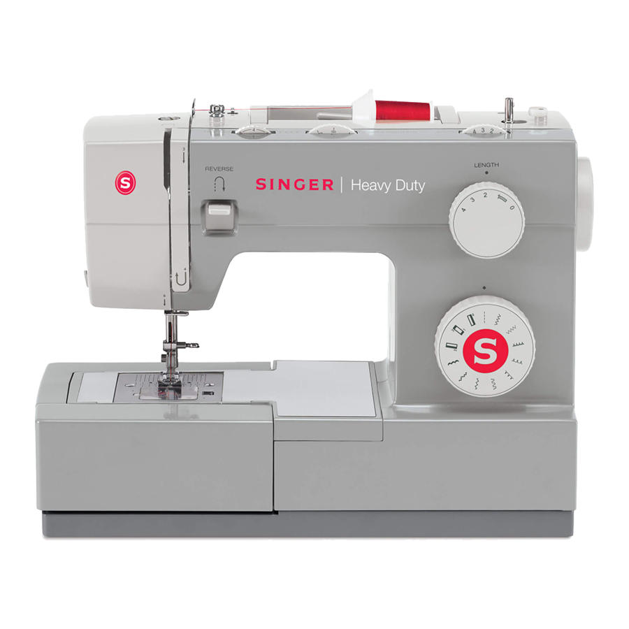
Names of principal parts

- Thread tension dial
- Presser foot pressure adjustment
- Thread take-up lever
- Reverse sewing lever
- Thread cutter
- Presser foot
- Needle plate cover
- Removable extension table/ accessory storage
- Three needle position dial
- Bobbin stopper
- Stitch width dial
- Stitch length dial
- Pattern selector dial
- Automatic threader (not on all model)
- One step buttonhole lever (not on all model)
- Horizontal spool pin
- Bobbin winding spindle
- Hole for second spool pin
- Handwheel
- Buttonhole stitch balance adjustment slot
- Power and light switch
- Main plug socket
- Bobbin thread guide
- Upper thread guide
- Face plate
- Handle
- Presser foot lifter
- Drop feed control
- Foot speed control
- Power cord
Removing methods of external parts
Sewing table
Keep the snap-in sewing table horizontal, and pull it in the direction of the arrow. (1)

Face plate
- Remove the operation cover (a).
- Loosen the screw (b) and remove the face plate. (2)

Base cover
- Lay down machine.
- Remove the screws (c, d, e, f, g, h). (3)
- Remove the base cover.

Free arm base
Remove the screws (i, j) and remove the free arm base. (4)

Free arm slab
- Remove the screw (k). (5)

- Remove the free arm slab. (6)


Arm top cover
Remove the screws (l, m) and remove the arm top cover. (7)

Back cover
- Remove the screws (n, o). (9)

- Remove the screw (p). (10)

- Remove the screw (q). (11)

- Remove the back cover. (12)


Front cover
- Remove the screw (r) which deeply inside the machine. (13)

- Loosen the screw (s) about 3mm. (14)

- Remove the pattern select dial (t, u) and remove front cover following direction of arrow. (15)


Adjusting methods of each part
Play of arm shaft
- Remove the face plate, arm top cover.
- Loosen the screws (a, b) of arm shaft collar (d). (1)
- Pull the hand wheel to the right. (2)
- Push the arm shaft collar (d) to right tightly against arm shaft bushing (c), and then fasten and secure the screws (a, b). (1)
- Be sure proper distance between arm shaft collar and arm shaft bushing. (1)
- Be sure arm shaft operates smoothly after adjustment.
- Arm shaft collar and arm shaft bushing being too tightly closed might cause insufficient operation of arm shaft.


Noisy - take up lever adjustment
- Remove the face plate and front cover.
- Turn around hand wheel, check noisy and movement.
- Remove the screw (a), push take up lever support (b) right to proper location, tight the screw (a). (1)
- If adjustment is too tight, it will be difficult to move during turn around hand wheel.
- If adjustment is too loose, it will be made noisy during turn around hand wheel.


Needle drop position adjustment
- Remove the face plate.
- Set the pattern selector dial to "
![]() " or "
" or "![]() ". Turn the stitch width dial to "0".
". Turn the stitch width dial to "0". - Loosen the screw (a) of needle bar supporter. (1)
- Turn needle bar supporter (b) forward / backward to adjust needle. (1)
Backward (↑) to move needle forward
Forward (↓) to move needle backward - Set needle position above center of needle plate and fasten the screw (a). (1)
* The space between needle and the tip of the shuttle hook holder should be 0.05~0.10 mm.

 " or "
 ". Turn the stitch width dial to "0".
Height of presser foot
- Remove the face plate and lift up presser bar lifter lever (a). (1)

- Loosen the screw (b) of presser bar bracket. (2)

- Place the gauge (c) (6.0~6.2mm) on top of needle plate. (3)

- Pull down the presser bar lifter lever so bottom of presser foot and top surface of gauge would meet.
- Secure tightly screw (b).
- The correct setting of gauge should be 6.0~6.2mm.


Needle flow at maximum zigzag width
- Remove the face plate, back cover and front cover.
- Set the pattern selector dial to "
![]() ". Turn the stitch width dial to "6".
". Turn the stitch width dial to "6". - Set the needle bar at its lowest point when it swings to left. Turn hand wheel to move the needle bar upward.
The vertical distance in which the needle point goes up at the left position from the top of the needle plate should be 3-5 mm. (1)

- If needle flow is less than 3-5 mm, loosen the arm shaft worm screws (a, b), and turn arm shaft worm (c) toward back (↑). (2)
- If needle flow is more than 5 mm, turn arm shaft worm (c) toward front (↓). (2)

- Tighten the screws (a, b) after making sure the needle flow is 5 mm.
 ". Turn the stitch width dial to "6".

Needle center position adjustment
- Remove the face plate.
- Set the pattern selector dial to "
![]() " or "
" or "![]() ". Turn the stitch width dial to "0".
". Turn the stitch width dial to "0". - Loosen the screw (a) of needle bar driving rod pin (b). (1)

- Adjust the needle bar driving rod pin (b) position, clockwise needle will turn left, counter clockwise needle will turn right.
Clockwise=left
Counter-clockwise=right - Make sure needle drops on middle of needle hole. After adjusting, re-tighten the screw (a). (2)


Needle position on zigzag
- Remove the face plate, back cover and front cover.
- Set the pattern selector dial to "
![]() ".
".
Turn the stitch width dial to "6".
Set the needle position dial to middle. - Adjust the needle by turning screw (a) of zigzag regulator crank complete clockwise / counter-clockwise. (1)
Clockwise = needle moves right
Counter-clockwise = needle moves left

- Make sure needle drops on left / right of needle hole with even distance to the edge of needle hole. (2)


Automatic needle threader adjustment
- Remove the face plate and turn hand wheel to raise needle bar to its highest position.
- Loosen the screw (a) of the threader stopper (b). (1)
- Move the stopper (b) upward and the threader hook will become higher.
Move the stopper (b) downward and the threader hook will become lower. - Adjust the stopper to the proper position for entering needle hole freely. (2 / 3)
- Fasten the screw (a) of stopper, and be sure the stopper (b) should be placed correctly. (1)


Adjustment of feed rock shaft and feed lifting rock cam
- Remove the cord reel cover and free arm cover.
- Turn the hand wheel to make the needle at its lowest point.
- Check if the feed lifting rock cam (a) and the screw (b) of feed rock cam (c) are parallel.
- If the screw of feed rock cam are not parallel: Loosen the screw (b) of feed rock cam (c) adjust the screw and front gauge correction to the middle.


Height of needle bar
- Remove the needle plate.
- Set the pattern selector dial to "
![]() " or "
" or "![]() ". Turn the stitch width dial to "0".
". Turn the stitch width dial to "0". - Remove the screws of rotary hook plate (a, b) and rotary hook plate, and take out the shuttle hook (c). (1)

- Set the needle bar at its lowest point. The gap between the upper end of the needle and the surface (d) of the hook ring should be 28.5 mm. (2)

- If it's not fit the standard of measure, loose the needle bar bracket (f) to adjust the needle bar's (e) position for measuring the correct height of needle bar. (3)


Timing of needle and hook
- Remove the face plate.
- Set the pattern selector dial to "
![]() ".
".
Turn the stitch width dial to "6". - Set the needle bar at its lowest point. Place a clamp (a) around the needle bar, slightly tighten its screw (c). (1)

- Place a 3.5mm gauge (b) between the needle bar support and clamp (a), tighten the needle clamp screw (c) and remove the 3.5 mm gauge (b).
- Turn the hand wheel so that the needle moves upwards and the needle clamp stops against the needle bar support.
- The tip of the hook should now be exactly behind the centre of the needle.

- If the distance is incorrect, loosen the screws (e, f, g) of lower shaft gear (d), and adjust shuttle hook to correct timing, and tighten the screw. (3)


Distance-needle-hook
- Remove the face plate, front cover, back cover and needle plate.
- Set the pattern selector dial to "
![]() ". Turn the stitch width dial to "6".
". Turn the stitch width dial to "6". - Take off the shuttle hook.
- Set the needle towards the lowest point of right side and lift it, make sure space between needle and the tip of the shuttle hook holder is 0.05~0.10mm. (1)

- If the space is incorrect:
- Loosen the screw (a) of the needle bar supporter.
- Push the needle bar supporter (b) backward (↑), and the space will become larger.
- Push the needle bar supporter forward (↓), and the space will become smaller. (2)


Play between shuttle driver shaft gear and lower shaft gear
- Remove the free arm cover and needle plate.
- Take off the shuttle hook.
- Loosen three set screws (a, b, c) of the lower shaft gear (d) and move the lower shaft gear to right or left against axial direction. (But the lower shaft gear never get out of shuttle hook gear (e).) (1 / 2)


- When the playing of the shuttle hook holder should be within 0.5 mm tighten three set screws (a, b, c).
- Make sure match timing of needle and hook.


Play of shuttle driver shaft
- Remove the needle plate.
- There are 2 gauges (a, b) for testing the play of shuttle driver shaft. (1)

- When you turn the hand wheel counterclockwise, the shuttle hook (c) will move to rotary hook plate (d), and generate the play between the shuttle hook and the rotary hook plate (e).
Using the gauge (a) to test the play, and the standard is 0.3 mm to 0.5 mm.
If the play is incorrect, loosen screws (f, g) of rotary hook plate (e) and adjust the plate to the proper position. Finally, re-tighten the screws. (2)

- When you turn the hand wheel clockwise, the shuttle hook (c) will move to rotary hook plate (e), and generate the play between the shuttle hook and the rotary hook plate (d).
Using the gauge (b) to test the play, and the standard is 0.6 mm to 1.0 mm.
If the play is incorrect, loosen screws (h, i) of rotary hook plate (d) and adjust the plate to the proper position. Finally, re-tighten the screws. (3)


Feed-dog height
When the feed dog is in it's highest position it should be 0.9 to 1.05 mm above the surface of the needle plate.
- Set the stitch length dial to "4".
- Remove the presser foot and free arm cover.
- Lift needle to its highest position.

- If its not between 0.9mm~1.05mm.
Loosen the screw (a) and adjust the screw (b). (2)

Clockwise = the feed dog will be raised.
Counter-clockwise = the feed dog will be lowered. - After adjusting tighten the screw (a).


Position of feed-dog in relation to the needle plate (left to right)
- Remove the cord reel cover and free arm cover.
- Loosen the screw (e) of the feed crank shaft (d) that is on the right side. (1)
- Loosen the screw (b) of the feed crank shaft (c) that is on the left side. (1)
 Step 1")
- Adjust the feed dog to center position by moving feed crank shaft (c) left / right in accordance with feed rock shaft (a) left / right. (2)
 Step 2")
- Tighten the screw (b) to fix the left side of feed crank shaft (c).
- Push right side feed crank shaft (d) to left and fasten the screw (e).
 Step 1")
 Step 2")
Upper thread tension adjustment
- Set the dial tension (a) to "4". (1)
- Use a dial tension gauge (150g) (b) to take measurement. (1)

- Put dial tension thread into gauge's hook and pull, the standard range should be 70~80g.
- Remove the face plate, back cover, and front cover.
- Adjust the tension by turning plastic screw (c) of dial tension regulator fortward/ backward. (2)

Forward = weaker
Backward = stronger - Re-check the standard range should be 70~80g.


Shuttle hook tension adjustment
- Remove the needle plate.
- Use a dial tension gauge (50g) (a) to take measurement. (1)
- Put dial tension thread into shuttle hook (b)(the same way as inserting the bobbin) and pull it out, the standard range should be 10~14g. (1)

- Adjust the screw (c) of shuttle hook to correct it if necessary. (2)
Turning clockwise makes dial tension stronger; turning counter-clockwise makes it weaker.
Re-check the standard tension range should be 10~14g.


Motor belt tension
- Remove the back cover, front cover and test tension of motor belt using belt tension gauge (a). Its standard measurement should be 100g. (1)

- Adjusting the belt adjusting plate (b) to regulate the improper belt's tension. The way to adjust is as following:
- Loosen the screws (c, d) of adjusting plate (b), and then move it to up, the belt will become loosen; move it to down, it will become more tighter. (2)
- Tighten the screws (c, d) after confirming the proper belt tension.


Drop point of needle
- Set pattern selector dial to "
![]() ".
". - Place a piece of blank paper on top of the needle plate and use presser foot to secure paper by pressing presser bar lifter lever down.
- Adjust the speed limiting adjustment lever to the slow speed and step on the foot controller lightly. Check if the needle can drop in the same place while moving forward and backward.
- If the drop point are not the same, take apart the plate (a). (1)
- If the stitch is too tight, adjust the screw of feed crank (b) anti-clockwise, and the needle will go frontward (↓). (1 / 2)
If the stitch is too loose, adjust the screw of feed crank (b) clockwise, and the needle will go backward (↑). (1 / 2)


 ".
". 

Forward and reverse stitching in buttonhole sewing (feeding pitch of reverse and forward stitching is not even)
- Sew the right side by setting the selector dial at "
![]() " and then the left side by setting at "
" and then the left side by setting at "![]() " (only for 4411/5511).
" (only for 4411/5511). - Set the pattern selector dial to "
![]() ".
". - Set the stitch length dial at "0.5" to "1".
- To sew by using thread in effect, to confirm delivery amount of forward and backward. (1) If forward and backward delivery amount not match, adjust by turning screw (a) of pattern cam contact plate clockwise / counter-clockwise. (2)
Counter-clockwise = strong
Clockwise = weak
 Step 1")
 Step 2")
 " and then the left side by setting at "
 " (only for 4411/5511).
  ".
".  Step 1")
 Step 2")
Buttonhole upper and lower stitching problem
- Remove the back cover.
- Set the pattern selector dial to "
![]() " (only for 4411/5511).
" (only for 4411/5511). - Set the pattern selector dial to "
![]() ".
". - Set the stitch length dial at "0.5" to "1".
- While buttonhole upper or lower stitching, remain the same distance tacking without delivering cloth. (1)
If cloth delivered forward, adjust screw (a) clockwise. (2)
If cloth delivered backward, adjust screw (a) counterclockwise.


 " (only for 4411/5511).

Bobbin winding problem
- Place empty bobbin on spindle and push it to the right.
- Put the thread into the spool rod, and put the spool rod cover on it.
- Lead thread from spool to back side of thread guide (a) by following the indication.
- Wind thread clockwise around bobbin winder tension disc. (1)

- Turn on the power switch and step on the foot controller to run the machine.
- Observe the shape of bobbin winding:
- When the lower part of bobbin winding is thicker, turn the screw (b) of threader guide counter-clockwise. (2)

- When the upper part of bobbin is thicker, turn the screw (c) of threader guide clockwise.
- When the lower part of bobbin winding is thicker, turn the screw (b) of threader guide counter-clockwise. (2)
- Observe the intensity:
- If bobbin winding is not 80 percent full, adjust by turning the screw (c) of bobbin winder bracket shaft clockwise. (3)

- If bobbin is over 80 percent full, adjust by turning the screw (c) of bobbin winder bracket shaft counter-clockwise.
- If bobbin winding is not 80 percent full, adjust by turning the screw (c) of bobbin winder bracket shaft clockwise. (3)
- Bobbin should be 80 percent full and evenly filled after adjustment.
- Push bobbin to left after adjustment before sewing.


® A registered trademark of The Singer Company Ltd. or its affiliates.
VideosSinger Heavy Duty 4423 Threading & Winding a Bobbin Video
Documents / ResourcesDownload manual
Here you can download full pdf version of manual, it may contain additional safety instructions, warranty information, FCC rules, etc.
Advertisement


Need help?
Do you have a question about the 4423 and is the answer not in the manual?
Questions and answers