Table of Contents
Advertisement
Quick Links
InterBox
User's Manual
This instruction manual contains essential information on how to use this Olympus product safely and effectively.
Before using this product, thoroughly review this instruction manual. Use the product as instructed.
Keep this instruction manual in a safe, accessible location.
DMTA031-01EN — Rev. B
October 2014
Advertisement
Chapters
Table of Contents

Summary of Contents for Olympus InterBox EIB-T-8-M-15-OM
- Page 1 DMTA031-01EN — Rev. B October 2014 This instruction manual contains essential information on how to use this Olympus product safely and effectively. Before using this product, thoroughly review this instruction manual. Use the product as instructed. Keep this instruction manual in a safe, accessible location.
- Page 2 Olympus Scientific Solutions Americas, 48 Woerd Avenue, Waltham, MA 02453, Copyright © 2009, 2014 by Olympus. All rights reserved. No part of this publication may be reproduced, translated, or distributed without the express written permission of Olympus. This document was prepared with particular attention to usage to ensure the accuracy of the information contained therein, and corresponds to the version of the product manufactured prior to the date appearing on the title page.
-
Page 3: Table Of Contents
DMTA031-01EN, Rev. B, October 2014 Table of Contents List of Abbreviations ..................v Labels and Symbols ................... 1 Important Information — Please Read Before Use ........5 Intended Use .......................... 5 Instruction Manual ........................ 5 Instrument Compatibility ..................... 6 Repair and Modification ....................... 7 Presence of Visual Interferences or Phantom Spots ............ - Page 4 DMTA031-01EN, Rev. B, October 2014 TOFD Connectors— for Models with TRPP 5810 Pulser/Preamplifier .... 21 Conventional UT Connectors .................. 23 Phased Array Probe Connectors ................23 Connecting the Phased Array Connectors ............24 InterBox Installation ....................27 3. Maintenance ....................29 Preventive Maintenance ...................
-
Page 5: List Of Abbreviations
DMTA031-01EN, Rev. B, October 2014 List of Abbreviations European Community light-emitting diode not applicable phased array polyvinyl chloride TOFD time-of-flight diffraction ultrasonic testing WEEE waste electrical and electronic equipment List of Abbreviations... - Page 6 DMTA031-01EN, Rev. B, October 2014 List of Abbreviations...
-
Page 7: Labels And Symbols
Safety-related labels and symbols are attached to the instrument at the locations shown in Figure i-1 on page 1. If any or all of the labels or symbols are missing or illegible, please contact Olympus. Location of TRPP rating plate... -
Page 8: Table 1 Content Of The Rating Label
The CE marking is a declaration that this product conforms to all the applicable directives of the European Community. See the Declaration of Conformity for details. Contact your Olympus representative for more information. The WEEE symbol indicates that the product must not be disposed of as unsorted municipal waste, but should be collected separately. - Page 9 DMTA031-01EN, Rev. B, October 2014 CAUTION To avoid the risk of electric shock, do not touch the inner conductor of the LEMO-00 P1 OUT and P2 OUT connectors for the TRPP 5810 pulser/preamplifier. Up to 200 V can be present on the inner conductor. TRPP 5810 LEMO 00 P1 OUT and P2 OUT connectors inner...
- Page 10 DMTA031-01EN, Rev. B, October 2014 Labels and Symbols...
-
Page 11: Important Information - Please Read Before Use
Instruction Manual This instruction manual contains essential information on how to use this Olympus product safely and effectively. Before using this product, thoroughly review this instruction manual. Use the product as instructed. -
Page 12: Instrument Compatibility
However, the operating principles remain the same. Instrument Compatibility The InterBox wiring interconnection box is compatible with the Olympus ancillary equipment listed in Table 2 on page 6. CAUTION Always use equipment and accessories that meet Olympus specifications. Using incompatible equipment could cause equipment malfunction and/or damage, or human injury. -
Page 13: Repair And Modification
DMTA031-01EN, Rev. B, October 2014 Table 2 Ancillary equipment (continued) Part number Item number Description TRPP-A-PWRC-AC-5M U8779647 Transformer (120 VAC to 240 VAC input to 12 VDC output) with 5 m power supply cable. TRPP-A-PWRC-OM-25M U8775216 25 m power supply cable linking TRPP 5810 to an OmniScan TRPP-A-PWRC-AC-25M U8775217... -
Page 14: Presence Of Visual Interferences Or Phantom Spots
DMTA031-01EN, Rev. B, October 2014 Presence of Visual Interferences or Phantom Spots IMPORTANT In a situation of physical proximity of powerful electromagnetic radiators, visual interferences or phantom spots maybe present. These interferences are temporary and their persistence is not permanent in comparison with physical features of the inspected part. -
Page 15: Safety Signal Words
DMTA031-01EN, Rev. B, October 2014 Safety Signal Words The following safety symbols might appear in the documentation of the instrument: DANGER The DANGER signal word indicates an imminently hazardous situation. It calls attention to a procedure, practice, or the like, which, if not correctly performed or adhered to, will result in death or serious personal injury. -
Page 16: Safety
DMTA031-01EN, Rev. B, October 2014 NOTE The NOTE signal word calls attention to an operating procedure, practice, or the like, which requires special attention. A note also denotes related parenthetical information that is useful, but not imperative. The TIP signal word calls attention to a type of note that helps you apply the techniques and procedures described in the manual to your specific needs, or provides hints on how to effectively use the capabilities of the product. -
Page 17: Equipment Disposal
Electronic Equipment (WEEE), this symbol indicates that the product must not be disposed of as unsorted municipal waste, but should be collected separately. Refer to your local Olympus distributor for return and/or collection systems available in your country. Important Information — Please Read Before Use... -
Page 18: Emc Directive Compliance
Retain packing materials, waybills, and other shipping documentation needed in order to file a damage claim. After notifying the carrier, contact Olympus for assistance with the damage claim and equipment replacement, if necessary. -
Page 19: Technical Support
DMTA031-01EN, Rev. B, October 2014 Technical Support Olympus is firmly committed to providing the highest level of customer service and product support. If you experience any difficulties when using our product, or if it fails to operate as described in the documentation, first consult the user’s manual, and then, if you are still in need of assistance, contact our After-Sales Service. - Page 20 DMTA031-01EN, Rev. B, October 2014 Important Information — Please Read Before Use...
-
Page 21: Introduction
Introduction This manual provides instructions and technical specifications for the InterBox, which is a wiring interconnection box that can be mounted on an Olympus scanner to simplify the cable connections between the scanner and its acquisition instrument. To help you understand and safely use the InterBox, this manual contains an equipment overview, connection details, maintenance instructions, and detailed specifications. - Page 22 DMTA031-01EN, Rev. B, October 2014 Introduction...
-
Page 23: Overview
DMTA031-01EN, Rev. B, October 2014 1. Overview The EIB-T-8-M-15-OM InterBox model is an example of one of the four available models (see Figure 1-1 on page 17). Depending on the model chosen, it is possible to connect one or two phased array probes, up to two pairs of TOFD probes, and up to eight conventional UT transducers to the InterBox. - Page 24 DMTA031-01EN, Rev. B, October 2014 The InterBox design eliminates the individual component cables between the scanner and the acquisition unit, and minimizes the encumbrance needed on the scanner to install the pulser/receiver extension box and the PA probe splitter. Depending on the model, the InterBox integrates a splitter (for phased array probes), a remote pulser/preamplifier (for TOFD inspections), or multiple UT channels, and is therefore well-suited for certain applications that require a combination of these features.
-
Page 25: Connections And Cables
DMTA031-01EN, Rev. B, October 2014 2. Connections and Cables Depending on the InterBox model, different instrument connectors and different cables are provided, and therefore the connection procedures may vary. Connections to the Acquisition Unit The InterBox is connected to an acquisition instrument by using an OmniScan or Hypertronics connector and cable. -
Page 26: Power-Cable Connector-For Models With Trpp 5810 Pulser/Preamplifier
DMTA031-01EN, Rev. B, October 2014 Power-Cable Connector—for Models with TRPP 5810 Pulser/Preamplifier The power-cable connector is marked with a red dot that must be aligned with a red dot on the connector receptacle on the InterBox before the connection is made (see Figure 2-2 on page 20 and Figure 2-3 on page 21). -
Page 27: Tofd Connectors- For Models With Trpp 5810 Pulser/Preamplifier
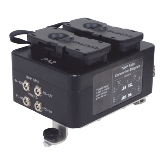
DMTA031-01EN, Rev. B, October 2014 The red LED illuminates when power is connected. InterBox with TRPP 5810 offers two different cables for a power-source connection (OmniScan or AC power). Figure 2-3 The power cable connection TOFD Connectors— for Models with TRPP 5810 Pulser/Preamplifier The TOFD connectors (pulsers and receivers) are mounted in the section labeled TRPP 5810 (see Figure 2-4 on page 21). -
Page 28: Figure 2-5 The Label With Probe-Connection Diagram
DMTA031-01EN, Rev. B, October 2014 The label on the InterBox face opposing the TOFD connectors provides the connection information for the integrated TRPP 5810 pulser/preamplifier (see Figure 2-5 on page 22): • P1 and P2 identify the pulser outputs • R1 and R2 identify the receiver inputs These codes, as well as the channel numbers, are marked next to each connector (see Figure 2-4 on page 21). -
Page 29: Conventional Ut Connectors
DMTA031-01EN, Rev. B, October 2014 Conventional UT Connectors The connections for conventional ultrasonic transducers are located on the right side of the acquisition-data cable (see Figure 2-6 on page 23). The channel numbers are marked next to each connector. Conventional UT connections with channel numbers Figure 2-6 The conventional UT connections The power output from the conventional UT channels is limited to 80 V. -
Page 30: Connecting The Phased Array Connectors
DMTA031-01EN, Rev. B, October 2014 Figure 2-7 The protective covers for phased array connectors (PA1 and PA2) The connector receptacles are identified as PA1 and PA2. The highest channel number on each PA range depends on how many channels are used for TOFD and conventional UT connections. -
Page 31: Figure 2-8 Removing The Pa Protective Covers
DMTA031-01EN, Rev. B, October 2014 To maintain the water resistance of the InterBox, the PA connectors must be covered by the protective covers even when there is no PA probe connected to the instrument. To connect a phased array connector to the InterBox Remove the phased array protective cover (see Figure 2-8 on page 25). -
Page 32: Figure 2-9 Aligning The Omniscan Connector
DMTA031-01EN, Rev. B, October 2014 Figure 2-9 Aligning the OmniScan connector To avoid connector-pin problems, always make sure that the connector is aligned straight with respect to the receptacle before pushing it into the receptacle. Push the connector into the receptacle to ensure a good connection (see Figure 2-10 on page 26). -
Page 33: Interbox Installation
DMTA031-01EN, Rev. B, October 2014 InterBox Installation The InterBox can be attached to an Olympus HSMT manual scanner with the supplied mounting bracket (see Figure 2-12 on page 28). A pair of T-nuts with thumb screws secures the InterBox to the frame of the scanner (see Figure 2-11 on page 27 and Figure 2-12 on page 28). -
Page 34: Figure 2-12 The Interbox Assembly Attached To The Scanner
DMTA031-01EN, Rev. B, October 2014 Note: older version of product is shown, but attachment method remains unchanged. T-nut Thumb screw Mounting bracket Figure 2-12 The InterBox assembly attached to the scanner Tighten the two thumb screws. Chapter 2... -
Page 35: Maintenance
DMTA031-01EN, Rev. B, October 2014 3. Maintenance The InterBox requires very little maintenance to keep it in good physical and working condition. A periodic inspection and, depending on the operating environment, periodic cleaning may be required. Preventive Maintenance The InterBox does not require preventive maintenance. Only a regular inspection of the product is recommended to ensure that the InterBox functions correctly. - Page 36 DMTA031-01EN, Rev. B, October 2014 Chapter 3...
-
Page 37: Specifications
DMTA031-01EN, Rev. B, October 2014 4. Specifications Table 4 InterBox—Technical specifications Element Description Instrument’s physical Overall dimensions 151 mm × 100 mm × 100 mm characteristics (L × W × H) (5.94 in. × 3.94 in. × 3.94 in.), without cable clearance. -
Page 38: Trpp 5810 Specifications
DMTA031-01EN, Rev. B, October 2014 Table 4 InterBox—Technical specifications (continued) Description Element PA connections Voltage (max.) 80 V PA connector type OmniScan connectors UT connections Voltage (max.) 80 V UT connector type LEMO-00 female connectors TRPP 5810 Connector type LEMO-00 female connectors (See “TRPP 5810 Specifications”... -
Page 39: Connector
The 12 V connector is used to supply power to the TRPP 5810 unit (see Figure 4-1 on page 33). Description Receptacle with 2 female contacts Manufacturer, number W.W. Fischer Inc., D.103.A051-130 Olympus, 21AB0133 Suggested cable connector W.W. Fischer Inc., S.103.A051-60/6.2-S Olympus, 21AB0132 Figure 4-1 The 12 V connector Specifications... -
Page 40: P And R Connectors
TOFD probes (see Figure 4-2 on page 34). Description Coaxial receptacle Manufacturer, number LEMO, EPS.00.250.NTN Olympus, 21AB0056 Suggested cable connector LEMO, FFC.00.250.CTAC31 Equivalent: W.W. Fischer, S.101.A004/3.0 Olympus, 21AB0016 Figure 4-2 The P and R connector... -
Page 41: Figure 4-3 Interbox Order Number Nomenclature
DMTA031-01EN, Rev. B, October 2014 EIB - T - 8 - P- 5- OM Extension, InterBox Cable length in Connector type TRPP 5810 (2- Total number of Cable type P: Flexible PVC EIB: 128 elements conventional UT meters channel TOFD OM: OmniScan cable (standard) -
Page 42: Table 10 Interbox-Channel Numbering
DMTA031-01EN, Rev. B, October 2014 Table 10 InterBox—Channel numbering Phased TOFD (TRPP 5810) Conventional UT InterBox array UT commercial model EIB-T-0-x-x-xx 1–62 65–126 EIB-T-4-x-x-xx 1–60 65–124 EIB-T-8-x-x-xx 1–58 65–122 EIB-NT-0-x-x-xx 1–64 65–128 EIB-NT-4-x-x-xx 1–62 65–126 EIB-NT-8-x-x-xx 1–60 65–124 EIB64-NT-0-x-x-xx 1–32 33–64 EIB64-NT-4-x-x-xx 1–30 33–62... -
Page 43: List Of Figures
DMTA031-01EN, Rev. B, October 2014 List of Figures Figure i-1 Labels location ...................... 1 Figure 1-1 InterBox model EIB-T-8-M-15-OM—Connector locations ......17 Figure 2-1 The acquisition-data cable ................19 Figure 2-2 Aligning the marks for the power connector ..........20 Figure 2-3 The power cable connection ................ - Page 44 DMTA031-01EN, Rev. B, October 2014 List of Figures...
-
Page 45: List Of Tables
DMTA031-01EN, Rev. B, October 2014 List of Tables Table 1 Content of the rating label ..................2 Table 2 Ancillary equipment ....................6 Table 3 InterBox—Pinout for the P and R connectors ........... 22 Table 4 InterBox—Technical specifications ..............31 Table 5 TRPP 5810—Power supply .................. - Page 46 DMTA031-01EN, Rev. B, October 2014 List of Tables...
-
Page 47: Index
DMTA031-01EN, Rev. B, October 2014 Index number on InterBox models 35 P connectors alignment mark, power connector 20 pinout 22 assembly, InterBox 28 references 34 phased array cable PA1 and PA2 24 outer material 19 probes 23 power (TRPP-5810) 20 R connectors CAUTION signal word 9 pinout 22... - Page 48 10 signal words 9 symbols 8 NOTE signal word 10 serial number format 2 signal words information notes 9 Olympus technical support 13 IMPORTANT 9 OmniScan connector 17 NOTE 10 order number nomenclature 35 TIP 10 organization, manual 15...
- Page 49 DMTA031-01EN, Rev. B, October 2014 technical support 13 unit cleaning 29 time-of-flight diffraction See TOFD use, intended 5 TIP signal word 10 UT connectors TOFD channel number 23 connectors 21 channel power output limit 23 probe-connection diagram 22 location 23 TRPP 5810 channel numbering 36 TRPP 5810 WARNING signal word 9...
- Page 50 DMTA031-01EN, Rev. B, October 2014 Index...
Need help?
Do you have a question about the InterBox EIB-T-8-M-15-OM and is the answer not in the manual?
Questions and answers