Table of Contents
Advertisement
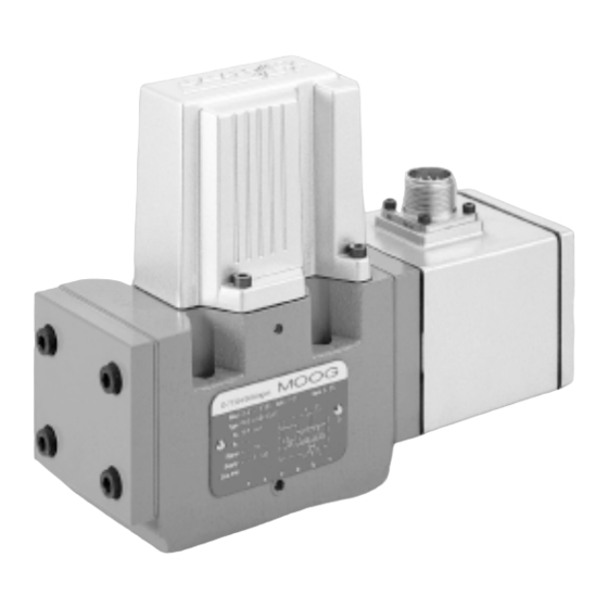
Servo and Proportional Control Valves with Integrated Electronics
1. INTRODUCTION
This manual provides instructions and procedures necessary
to install, operate and troubleshoot the Moog D661 Series Servo and Propor-
tional Control Valves.
Series Models
Series G
Servovalve with nozzle-flapper or ServoJet
stage, spool in bushing, without additional mechanical
feedback
Series S
Servovalve configured like version G, but with additional
mechanical feedback
Series H
Servovalve configured like version S, but with improved
performance (high response)
Series P...A/B
Proportional valve with ServoJet
without additional mechanical feedback
Series P...F/G
Proportional valve configured like version P...A/B, but
with nozzle flapper pilot stage and additional mechanical
feedback
2. OPERATION
General
The Servovalves D661-G, S and H Series and the Proportional Flow
Control Valves D661-P Series are throttle valves for 2-, 3- and 4-way
applications. With proportional flow control valves, 5-way applications are also
possible. These valves are suitable for electrohydraulic position, velocitiy,
pressure or force control systems with high dynamic response requirements.
D661-G, S and H
The spool of the main stage is driven by a nozzle flapper or ServoJet
pilot stage, optional with or without additional mechanical feedback (nozzle
flapper only).
With versions D661-S and H in case of an electrical supply failure
the spool is moved into a preferred position by action of an additional
mechanical feedback.
CAUTION
DISASSEMBLY, MAINTENANCE, OR REPAIR OTHER THAN IN ACCORDANCE WITH THE
INSTRUCTIONS HEREIN OR OTHER SPECIFIC WRITTEN DIRECTIONS FROM MOOG WILL
INVALIDATE MOOG'S OBLIGATIONS UNDER ITS WARRANTY.
Installation and Operation Instruction
®
pilot
®
pilot stage, spool in body,
ELECTROHYDRAULIC VALVE CUT-AWAY
Bushing
®
Figure 1 Moog Series D661-G Series, without additional mechanical feedback
ISO 4401 Size 05
Spool
X T
A
P
B
T
Y
2
D661 Series
Screw Plug for Null Adjust
Connector
Advertisement
Table of Contents

Related Manuals for Moog D661 Series


Summary of Contents for Moog D661 Series
- Page 1 Installation and Operation Instruction Servo and Proportional Control Valves with Integrated Electronics 1. INTRODUCTION This manual provides instructions and procedures necessary to install, operate and troubleshoot the Moog D661 Series Servo and Propor- tional Control Valves. Series Models ® Series G...
- Page 2 Thus, the position of the spool is proportional to the electric command signal. to avoid potential damage. Therefore, failsafe versions are offered as an option for the MOOG proportional valves. After external triggering, this failsafe function causes a defined metering spool position.
-
Page 3: Technical Data
With failsafe versions R and L, a defined spool position is reached Electric characteristics of the 2/2-way solenoid valve when the electric supply to the valve electronics is switched off ATTENTION while the pilot pressure is still applied. With version M, the resulting spool Connector wiring position is undefined. -
Page 4: Safety Instructions
Pay attention to cleanliness of mounting surface and surroundings when Correct Application installing the valve. The D661 Series Valves are control valves suited for electrohydraulic Use lint-free tissue to clean! position, velocity, pressure and force control. Before installation, remove shipping plate from the valve and save it The valves are designed for flow control in hydraulic systems that for later use. -
Page 5: Maintenance
Return failed valve to the factory. This information is valid for new installations to be put into operation Moog valves can only be repaired at Moog Service Centers (for addresses as well as for repair cases. see back page of this operation instructions). -
Page 6: General Requirements
(not connected at the mating connector). The input See also MOOG Application Note AM 353 E. pins D and E are inverting. Connector Wiring - Type code S (see sticker on the electronics housing) For valve with 6+PE-pole connector according DIN 43563, connector (metal) with leading ground pin ( ). - Page 7 Valve electronics with supply voltage ± 15 VDC and 11+1 pole Monitoring output bayonet connector The actual spool position value can be measured at pin F. This signal can be used for monitoring and fault detection purposes. Alternate connector for certain valve models Command signal 0 to ±10 V The spool stroke range corresponds to ±10 V.
- Page 8 ± Valve electronics with supply voltage 15 VDC and 6 pole connector Monitoring output (without protective grounding) The actual spool position value can be measured at pin F. This signal can be used for monitoring and fault detection purposes. Command input ±...
- Page 9 Valve electronics with supply voltage ± 15 VDC and 12 pole bayonet Monitoring output connector (without protective grounding) The actual spool position value can be measured at pin F. This signal can be used for monitoring and fault detection purposes. Command input Command signal 0 to ±10 V Command signal 0 to ±10 V...
- Page 10 See also MOOG Application Note AM 353 E. Connector Wiring - Type code letter S (see sticker on the electronics housing)
- Page 11 Valve electronics with supply voltage 24 Volt and 11+PE - pole connector Monitoring output ± Actual value 0 to 10 V Command input Valves with voltage and current command input ± Command signal 0 to 10 V The actual value, i. e. the spool position, can be measured between pins 6 and The spool stroke of the valve is proportional to (U –...
-
Page 12: Electrical Null Adjustment
(not part of the valve delivery) Clean grease (mounting and insertion of O-rings) Part Description D661- Qty. Part Number Mating Connector, The D661 Series valves require tools for installation, set up, null waterproof, protection IP65 adjustment and filter replacement. 6+PE-pole DIN 43563 B97007 061 11+PE-pole... -
Page 13: Troubleshooting Chart
392/EWG, Annex II B, is available for servo and proportional valves D661 returned to Moog for repair. Moog does not authorize any facilities other Series and will be supplied upon request. -
Page 14: Ordering Information
ORDERING INFORMATION Model-Number Type designation D661-G, S and H Electric supply Specification status ± 15 VDC ± 3% – Series specification Preseries specification 24 VDC (18-32 VDC) Special specification Signals for 100% spool stroke Command Output Model designation ±10 V ±10 V assigned at the factory ±10 mA... - Page 15 Model-Number Type designation D661 Specification status Electric supply ± 15 VDC ± 3% – Series specification Preseries specification 24 VDC (19 to 32 VDC) Special specification Signals for 100% spool stroke Model designation Command Output for supply voltage ±10 VDC ±10 VDC 2 (11+PE diff) assigned at the factory...
- Page 16 D661SERIES INSTALLATION AND OPERATION INSTRUCTION counterbore Moog Inc., East Aurora, NY 14052-0018 Telephone: 716/652-2000 Fax: 716/687-7910 Toll Free: 1-800-272-MOOG http://www.moog.com The products described herein are subject to change at any time without notice, including, but not limited to, product features, specifications, and designs.
Need help?
Do you have a question about the D661 Series and is the answer not in the manual?
Questions and answers