
Related Manuals for Gio Electric ELEMENT


Summary of Contents for Gio Electric ELEMENT
- Page 1 ELEMENT MOBILITY SCOOTER OWNERS MANUAL - EN PRIOR TO FIRST USE, READ THIS MANUAL COMPLETELY AND ATTENTIVELY! IMPERATIVELY FOLLOW THE SAFETY INSTRUCTIONS! NONOBSERVANCE CAN LEAD TO INJURIES! CAREFULLY KEEP THIS MANUAL!
- Page 2 PLEASE INSPECT YOUR GIO ELECTRIC ELEMENT MOBILITY SCOOTER UPON ARRIVAL AND REPORT ANY DAMAGES THAT MAY HAVE OCCURRED DURING SHIPPING ATTENTION ⚠ This scooter is designed only for one adult only. Never exceed the max load capacity of the vehicle. 460lbs(209kg) This scooter is designed for even surfaces with a maximum recommended incline of 12°...
- Page 3 Table of Contents Diving Safety Scooter & Control Diagrams Scooter Assembly Operating Your Scooter Maintenance & Care Specifications & Troubleshooting Warranty Information Driving Safety Take time to practice and get a feel for your scooter’s handling in a safe location away from pedestrians and traffic. Inspect the scooter prior to each use AVOID driving while fatigued or tired AVOID driving under the influence of drugs or alcohol...
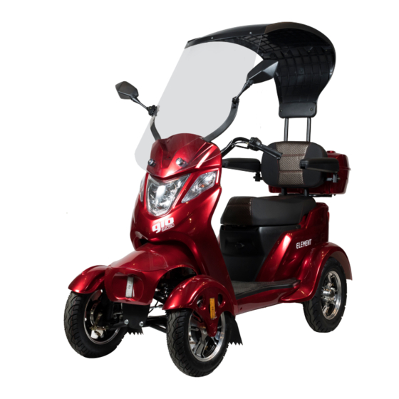
- Page 4 Scooter Diagram 1) Canopy 9) Footrest 2) Mirrors 10) Seat 3) Handlebars & Controls 11) Storage Compartment 4) Steering column & LCD Display 12) Rear lights/turn signals 5) Ignition Switch 13) Rear wheels/brakes 6) Headlight & Turnsignals 14) Charging port 7) Front wheels/brakes 15) Battery, Controller, 8) Front fender/mud flaps...
- Page 5 Control Diagram a) Twist Throttle f) Parking Brake b) Rear Brake Level g) Front brake lever c) Speed Setting Switch h) Brightness Switch d) Light On/Off i) Turn Signal Switch e) Forward/Reverse Switch j) Horn Switch...
- Page 6 SCOOTER ASSEMBLY Hardware Guide (a) 5.5cm M10 (b)4cm M8 (c) 3cm M8 (d) 2.5cm M6 (e) 2cm M6 (f) 4cm M6 (g) 2.5cm M6 (h) 2cm M6 (i) Larger (j) Smaller (m) M10 (n) M6 (o) Large (p) Medium Please note that this visual hardware guide is for comparative reference only.
- Page 7 Hardware List Assembly Section Part Size Handlebars Bolt (a) 5.5cm M10 Spacer (m) M10 Fenders & Hood Phillips Head Bolt (h) 2cm M6 Bolt (e) 2cm M6 Bolt (d) 2.5cm M6 Windshield Brackets Bolt (b) 4cm M8 Screw (j) Small Backrest Bolt (c) 3cm M8...
- Page 8 Assembly Instructions Your GIO Element arrives partially assembled and requires assembly before use. For a complete assembly video from our technician checkout the following video online for the step by step process https://youtu.be/KeWwoIXZ1lE To begin assembly, remove the scooter and all pieces from the metal frame and box it arrived in.
- Page 9 Steering Handlebars Insert the handlebars on top of the steering column aligning the holes. Insert the large bolt (a) and halfmoon spacer (l) from the front facing side of the handlebars and align the spacer with the cut out. Secure the corresponding nut (m) on the bolt and secure using 2 wrenches.
- Page 10 Please make sure the cable for the integrated LED lights is on the outside of the bracket, not between the bracket and tire. Attach each fender with bolts (h) in each of the 3 holes. Connect the connector from the fender lights to one of the 3 connectors on the front end.
- Page 11 Next align the side holes on the hood with the side mounting brackets. Please note the hood may have warped during shipping, if the holes do not align carefully bend the hood so they do. Once aligned insert bolts (e) on each side and then tighten them and the front bolt. Windshield brackets Remove the windshield bracket cover secured with packing material, and set aside.
- Page 12 Backrest To install the support for the backrest the seat must be temporarily removed to attach the support to the frame. First open the seat compartment by inserting the key into the ignition and turning it to the left to unlatch it. With it now unlatched you can lift the seat cushion forward and remove the 4 bolts holding the underseat tray in position.
- Page 13 Now is also a perfect time to double check that all the electrical connections on your scooter are secure. Reconnect any separated connection or tighten any loose ones. Please note there will be extra connections on the controller, not used in the function of your scooter. With the trim removed align the holes on the backrest support with those on the frame and secure into place with bolts (c).
- Page 14 To complete the backrest the seat cushion and cushion back panel have to be installed. First attach the back panel by aligning the holes on the panel with those on the support and screwing (i) into place. Next align the cushion into place and screw (i) into place through the back panel.
- Page 15 To complete this finish on the rear top install the cover over the mounting connections just installed with bolts(h). (Not pictured) Rooftop The rooftop is the next section installed for the scooter’s canopy and attaches to the previously installed rear top. Insert the smaller clips (u) into the corresponding slots on the rooftop, align the now threaded holes with the ones on the rear top section and screw (j) into place.
- Page 16 Windscreen (Part 1) The windscreen is the last section of the attached canopy. It attaches first to the front of the scooter and then to the rooftop. First locate and install 2 large rubber grommets (p) into the lower holes and 4 (o) medium rubber grommets into the upper holes.
- Page 17 Start and place the rubber mirror base grommets on the back of each mirror. Align the holes of each mirror with the grommet holes on the windshield and the ones on the windshield bracket. Secure the mirrors into place with the bolts (f) on the outside, and the nuts (n) on the inside.
- Page 18 Arm Rests Insert each arm rest into the corresponding bracket on the backrest support and secure it with bolts (c). Cargo Container Place the storage container on the mounting plate located on the rear of the backrest support. Align the holes on the container with those on the mounting plate and secure with nuts (n) and bolts (d).
- Page 19 (j) into place on both sides. Your GIO Element should now be fully assembled. The Element does not arrive fully charged. Please charge before your first use.
- Page 20 Driving your Scooter The Element features a variable twist throttle on the right handlebar. (See control diagram) Gently twist the throttle grip to slowly accelerate to the desired speed. Avoid twisting too hard or too quickly as this may result in jumps in accelerations making steering less controllable.
- Page 21 Using the electric features of you Scooter The Element has several features that have controls also located on the handlebars. On the right handlebar, the center toggle switch can be set to all lights ON ( ☼ ) including headlight, daytime running lights only (>DⱭ<) or lights OFF ( ○...
- Page 22 Maintenance and Care The GIO Element requires minimal maintenance which can be performed by most users, a friend or family member, or scooter technician. Visually inspect your scooter regularly for any signs of damage, especially after any collisions or accidents.
- Page 23 Prolonged exposure to subzero temperatures may result in damage to the battery. Tires The Element is equipped with tubeless tires, these require less maintenance, and are less prone to flats compared to traditional tube tires. However, damage and flats are still possible. The condition of your tires not only directly affects the ability to drive your scooter but also its general performance.
- Page 24 In the event your tire is unable to hold air. Check it for any cuts or punctures. In the event of a puncture the tire can be repaired at home with a basic patch kit for tubeless tires, or by a shop that repairs tires. In the event that there is a cut or greater damage to your tire(s) replacement parts are available to order, please contact customer service.
- Page 25 Troubleshooting Issue Possible Cause Solution Battery gauge doesn’t Loose connection near the Check connections, tighten register anything when, power switch or battery pack. loose connections scooter is ON Battery is completely Charge battery discharged. Scooter turns ON and has Motor wire is loose or Check connections near the battery charge but doesn’t disconnected...
- Page 26 There are no warranties that extend beyond the description in this limited warranty. GIO Electric guarantees this product, including charger, motor, controller, to be free of manufacturing defects for a period of 12 months. All warranty periods commence from the date of shipment.
- Page 27 11400 Twigg Place Unit 1 Richmond, BC, V6V3C1 CANADA E-Mail: support@gioelectric.zendesk.com Website: www.giomobility.com Tel: 1-855-907-4211 © GIO Mobility, 2022. All Rights Reserved...
Need help?
Do you have a question about the ELEMENT and is the answer not in the manual?
Questions and answers