Table of Contents
Advertisement
Serial Flash Programming solutions
The Innovative solution to update the Serial Flash on board and Offline
High performances
USB High speed support
In Circuit Programming (program on board SPI Flash)
Socket Programming (program SPI flash in the socket)
Start Button function
Standalone mode (SF600Plus): Update the Serial flash without computer
Support single, Dual and Quad IO
Three software optimized interfaces:
- Engineering Interface for expert
- Command Line for automatic control
- Production interface for operator
Multi-Programmers support through USB
Friendly and powerful tool with free life time update via Website
Portable programmer
Advanced I/O control
www.dediprog.com
SF600/SF600
SF600/SF600Plus
Plus
Serial Flash Programming solution
1
Advertisement
Table of Contents

Related Manuals for DediProg SF600


Summary of Contents for DediProg SF600
- Page 1 Plus SF600/SF600 Serial Flash Programming solution SF600/SF600Plus Serial Flash Programming solutions The Innovative solution to update the Serial Flash on board and Offline High performances USB High speed support In Circuit Programming (program on board SPI Flash) ...
-
Page 2: Table Of Contents
DediProg. However, no responsibility is assumed for errors that might appear. DediProg reserves the right to make any changes to the product and/or the specification at any time without notice. No part of this document may be copied or reproduced in any form or by any means without prior written consent of DediProg. -
Page 3: Products Comparison
I. Products comparison The Universal Programmers available on the market are not optimized for the Serial Flash and offer low performances for high price. DediProg team has therefore developed the optimum solutions to cover all our customers’ needs. Table1: Comparison table... -
Page 4: Sf600 And Sf600Plus Description
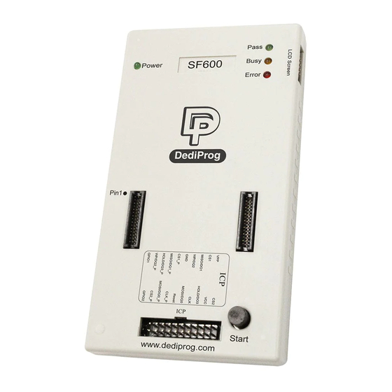
Plus SF600/SF600 Serial Flash Programming solution II. SF600 and SF600Plus description SF600 and SF600Plus have been designed to offer the best possible performances to program the SPI Flash in different conditions. 2.1 Interface description Fig 1: SF600/SF600Plus Programmer A. USB Connector F. - Page 5 The Start button is operations from the programmer either in USB mode. By pressing and hold 2 seconds the start button, the SF600 and SF600Plus starts to execute the operation procedures defined in the software Batch configuration when working in USB mode or in the project pre-loaded to the SF600Plus when working in standalone mode.
-
Page 6: Icp Header Description
Flash. The flat cable is flexible and convenient to manipulate. It must be kept as short as possible to not impact the signal quality. Even if SF600 and SF600Plus strong buffers can drive high capacitance, the communication failure can occur due to weaker driving capability of the on board Serial Flash. - Page 7 MOSI/DQ0 when memory work in single IO mode. Bi-directional when memory works in Dual or Quad IO mode. Open drain output driven low prior any SF600/SF600Plus operation. Reset/IO3 can be used to turn on the application Reset/IO3 isolation circuit or reset the target system in order to drive the Serial bus in High Impedance.
-
Page 8: Application Header
2.3 Application Header 2.3.1 Backward compatibility with SF100 The SF600 and SF600Plus pin header assignment has been changed versus the SF100 in order to support the new Serial Flash features like Quad IO and to be compatible with others DediProg development tools like EM100pro SPI Flash emulator and Backup Boot Flash tools. -
Page 9: Programming Methods
Fig 3: SF600/SF600Plus connected to the application header 3.2 SPI bus in High Impedance The SF600/SF600Plus reset signal can be used to reset the target board and switch the application controller in reset mode. User must check if the SPI bus is released in high impedance during this mode to prevent any conflict between the programmer and the application controller. -
Page 10: Backup Boot Flash Method
SPI flash on the application which it is disabled. The backup serial flash can then be accessed at any time by the SF600 / SF600Plus without any possible conflict with the application controller. In this case, SF600 / SF600Plus cannot update directly the on board Serial Flash to avoid conflict with the controller. -
Page 11: Socket Programming
Serial Flash Programming solution 3.5 Socket Programming The SF600 and SF600Plus have been designed to support the DediProg socket adaptors and offer the socket programming flexibility. Different sockets adaptor are provided to fit the different Serial Flash packages proposed in the market. Please note that socket mode only supported Single and Dual IO. - Page 12 Plus SF600/SF600 Serial Flash Programming solution Note: The new socket adaptor has a white triangle marker on the left and lower side of the socket. Shown as below To avoid plugging the wrong direction to the socket header, please ensure the marker to aim at the Pin 1 position.
-
Page 13: Sf600 And Sf600Plus Software
User can also edit the buffer, files and SPI Flash content and compare. DediProg provides three different users interface to fit better our customers’ needs. For more information on the SF600 and SF600Plus software, please refer to the user manual. 4.1.1 Engineering User Interface The engineering user interface has been designed to offer the expert features for engineers during development. -
Page 14: Command Line Interface
Benefits: - SF600 and SF600Plus can be controlled by the compiler in order to automatically program the Serial Flash with the new code for trials - SF600 and SF600Plus can be integrated in your production line and be controlled by the In Circuit Tester to program the on board serial flash after the testing has been successfully performed. -
Page 15: Production User Interface
Plus SF600/SF600 Serial Flash Programming solution Fig 8: Window DOS interface 4.1.3 Production User interface The production user interface has been designed to offer the optimum interface to control volume programming: Simple interface to fit to the operator needs Project loading to reduce the human errors Monitor multiple programmers operation in one window Control your ongoing project performances (counters, failure rate...etc.) -
Page 16: Standalone Mode (Sf600Plus)
In order to perform standalone programming, the contents and the programming operation procedures have to be pre-downloaded to the SF600Plus embedded memory through the USB with the software provided by DediProg. Prepare a standalone programming project Open DediProg Production Software. -
Page 17: Specification
The ICP connector is a 10x2 pin header straight type with 2.54mm pitch. It is used to control the application SPI Flash, and if necessary supply the SPI Flash, provide the high voltage to the SPI Flash, or reset the application chipset, etc. Table 6: SF600 and SF600Plus Pin Header description: MISO/DQ1 Hold/DQ3... - Page 18 ICP Vcc pin at 3.3V b) by the application according to the SPI Flash specification The SF600 and SF600Plus have been designed with a Serial diode on the Vcc to protect against any conflict with the application Vcc.
- Page 19 Plus SF600/SF600 Serial Flash Programming solution Remark: the total capacitance added on the application SPI bus will also depend on the ICP cable length. The ICP cable length must be reduced at the minimum. The SPI flash output buffer capability (MISO) is limited compared to the programmer performances.
-
Page 20: Icp Timing
OFF MOSFET and isolate the SPI bus when programmer is working. A. If No programmer operation is on going All our SF600 and SF600Plus outputs are equivalent to high impedance. B. When an operation is requested on the user interface - IO1, IO2 are kept in Input by default (High Impedance) - Reset/IO3 signals are driven Low. -
Page 21: Host Pc Requirements
Serial Flash Programming solution E. When operation on the memory is finished The SF600 and SF600Plus are witched in High impedance so the application board can boot with SF600 and SF600Plus connected without conflict. Fig 12: IO and SPI timing 5.2.4 Host PC requirements... -
Page 22: Programming Performance
Plus SF600/SF600 Serial Flash Programming solution VI. Programming Performance Table 8: Programming and verify in USB mode SPI Flash 8 Mbit 16 Mbit 32 Mbit 64 Mbit 128 Mbit 256 Mbit 512Mbit 1Gbit Densities Program+ 115s 199.5s 532s Verify W25X80V... -
Page 23: Vii.revision History
Support:sales@dediprog.com www.dediprog.com.dediprog.com Information furnished is believed to be accurate and reliable. However, DediProg assumes no responsibility for the consequences of use of such information or for any infringement of patents or other rights of third parties which may result from its use. Specifications mentioned in this publication are subject to change without notice.
Need help?
Do you have a question about the SF600 and is the answer not in the manual?
Questions and answers