Table of Contents
Advertisement
Advertisement
Table of Contents

Related Manuals for Vatech PAX Duo3D


Summary of Contents for Vatech PAX Duo3D
-
Page 3: Table Of Contents
Contents Chapter 1. Introduction ............6 1.1. Product Overview ........................6 1.2. Product Features........................6 1.3. Product Components ....................... 7 1.4. Marks & Graphic Symbols ....................... 8 Chapter 2. Components and Functions ....... 10 2.1. Hardware Components and Functions .................. 10 2.2. - Page 4 5.5. Installing 2 USB-type License Keys..................41 Chapter 6. Installing software ..........43 6.1. Installing Imaging Software and Frame grabber Driver ............44 6.2. HASP Device Driver ....................... 54 6.3. DirectX Driver ......................... 56 6.4. Serial Card Driver Setting ...................... 58 Chapter 7.
- Page 5 7. If there is any doubt about operation or condition, do NOT install the system until a VATECH & E-WOO customer support team checks and confirms its reliability.
- Page 6 Guidelines for Protection against Radiation The X-ray system may cause injury to the patient if used improperly. The instructions contained in this manual must be read and followed when operating PaX-Duo3D. The world standard regulations pertaining to radiation safety must be observed. When exposing X-ray, User must be behind a protective wall, or take other protective actions.
- Page 7 Introduction This chapter describes the overall features and technical specifications of the system. Installation manual...
-
Page 8: Chapter 1. Introduction
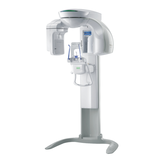
Chapter 1. Introduction 1.1. Product Overview PaX-Duo3D is the diagnostic system which consists of Advanced Digital Dental Tomographic and Panoramic X-ray units. Its economical CT is completely distinguished from among the other existing technology of Tomography. More so, its advanced digital imaging process allows for a considerably efficient diagnosis, a variety of management information, and real-time sharing of image information in a network. -
Page 9: Product Components
The PaX-Duo has been designed to carry out the following radiological examinations. Panorama Normal Panorama Special Dental CT TMJ Imaging mode Sub mode Standard Normal Fast Panorama Open Close Mandible Maxillary Occlusion Right CT TMJ left 1.3. Product Components <Hardware Components> Equipment main system User's manual Installation CD... -
Page 10: Marks & Graphic Symbols
1.4. Marks & Graphic Symbols TYPE B Equipment Radiation hazard This CE symbol grants the product compliance to the European Directive for Medical Devices 93/42 as a class IIB device, as Authorized by Grand- Duche De Luxemburg. PaX-Duo3D... - Page 11 Components and functions This chapter describes the overall features and functions of the system. Installation manual...
-
Page 12: Chapter 2. Components And Functions
Chapter 2. Components and Functions 2.1. Hardware Components and Functions LED Lamp Emergency Switch Sensor Module Chinrest LCD Panel Handle Frame Column LED Lamp: Indicating the current X-Ray emission activity of unit. While it stays green when the unit is idle, led lamp turns orange when the unit is in operation. Emergency switch: stop the movement of the unit when it abnormally operates. -
Page 13: Dimension Of Pax-Duo3D
This configuration may differ depending on the specification of your product. 2.2. Dimension of PaX-Duo3D Installation manual... - Page 14 PaX-Duo3D...
- Page 15 Preparing for installation This chapter describes the pre-installation for the system. Installation manual...
-
Page 16: Chapter 3. Preparing For Installation
Chapter 3. Preparing for Installation 3.1. Checking Packages The installers and/or supervisor should check the following before system installation. 3.1.1. Checking “ShockWatch” and “TiltWatch” The “ShockWatch” and “TiltWatch” become red in case for cartons of being damaged. Check whether “ShockWatch” and “TiltWatch “on each carton has been damaged. If it is the case, please contact your shipping company, agent or E-WOO. -
Page 17: Checking Carton No. 1
[Components in Packages] Part Name Specification Q'TY With Vertical Handler Vertical Front Case+LED Case Vertical Column Vertical Top Case Assembly, Vertical Left Case Rotating Unit Assembly Vertical Right Case Column Back Case Cover Base Foot Board If the serial numbers don’t match, please don’t install the system. Please make sure each carton isn’t damaged. -
Page 18: Checking Carton No. 2
3.3. Checking Carton No. 2 [Components in carton No. 2] Picasso Duo Description Q’TY Base Accessory box For the Panoramic unit, column, Base, and Accessory boxes are packed separately. PaX-Duo3D... -
Page 19: Checking The Packing List Of The Accessory Box
3.4. Checking the packing list of the accessory box Cable Tie 70mm Hub Cable LAN Cable 8PIN LAN for PANO 5M Head Rest Rubber Cap Disposable Bag Small size Cover Column Bottom Cover Column Back Case Cover Column Top Cover Switch Up/Down Handle table... - Page 20 Column Support Block A Block Column Support Block A Column Support Block B Wrench Bolt 12*40 Screw T/T 4*12 Toothless support Sinus support Wrench Bolt 8*25 Flat Headed Bolt 4*10 Truss Bolt 4*10 Wrench Bolt 8*40 Truss Bolt Flat Headed Bolt Chin Support With Pin(2EA) Normal support...
-
Page 21: Replacement Parts And Positioning Accessories
3.5. Replacement parts and positioning accessories The unit comes with 4 different types of the support for the patient positioning to acquire the better quality of images. ① Normal bite ② Toothless support ③ TMJ support ④ Sinus support Installation manual... -
Page 22: Tools Require
3.6. Tools require Name Specifications Q’ty (ea) Remark L-Wrench set 1.5/2/2.5/3/4/5/6/8/10 MM (9 1Set 1Set PCS) Monkey Spanner 8” Digital tester AC/DC Tester (Multi Meter) Driver Long, Middle, Short 1Set Cross type Cutter Long Nose Flier Side Cutting Flier Iron Block For Level Spirit Level SB300... -
Page 23: Unpacking Carton
3.7. Unpacking Carton Installation manual... - Page 24 PaX-Duo3D...
- Page 25 Installing the unit This chapter describes how to install the system properly and safely. Installation manual...
-
Page 26: Chapter 4. Installing The Unit
Chapter 4. Installing the unit At least 3 persons are needed to carry and install the product to prevent it from being damaged. Before installing the column, please check if the floor condition is proper for system installation. Back Left Right Front PaX-Duo3D... -
Page 27: Assembling The Column And The Base Plate
4.1. Assembling the column and the base plate Step 1. Attach the column on the base Please keep a minimum of 300mm distance from the wall because you need space for cable work & covers assembly on the backside. 1-1. Unpack the Picasso Duo and assemble the column with the base plate, as shown below. 1-2. - Page 28 1-3. Please combine the Column with the base plate, as shown below. The following figure shows the completion result. (See the circled area) PaX-Duo3D...
- Page 29 1-4. Erect the column with help from others, as shown in the illustration below. At least 1 person should grasp the bar on the column to support the system. Installation manual...
- Page 30 1-5. Screw 2 wrench bolts [M8*25] (Accessory No. 25) to fix the column to the base. Step 2. Install the column and supply electricity 2-1. Remove the wrench bolt that is locking the Rotating unit. 2-2. Move the Rotating unit slowly until you hear the “Tick” sound. Move the Rotating Unit slowly so as not to cause malfunctioning of the product.
- Page 31 2-3. Insert the main power plug into the power outlet. Then connect the Column up/down switch (Accessory No. 9). 2-4. Please turn on the Power Switch. 2-5. Press the Up/Down Switch buttons. Adjust the column height slightly upward, enough for fixing the wrench bolts spanner.
- Page 32 2-6. Screw the Fixing block with 6 wrench bolts [M12*40, M8*40] (Accessory No.21 & No. 28) and 6 set of bolts [M8*25 – Wrench bolt, 8Φ – Flat washer & spring washer] (Accessory No.25). 2-7. Attach the base cover. (Accessory No. 7) PaX-Duo3D...
- Page 33 2-8. Take out the 2 wrench bolts at the top of the column and remove the Handle pipes. Then, re- attach the block and screw back the 2 wrench bolts. When removing the Handle pipes, please hold the Bracket and Handle pipes while taking out the bolts.
- Page 34 3-2. Attach the vertical front cover with 2 4*10 flat headed bolts. (Accessory No. 26) PaX-Duo3D...
-
Page 35: Balancing The System After Finishing Unit Assembly
4.2. Balancing the system after finishing unit assembly <Balance the system on the ground> ① Prepare the spirit level ② Position the Rotating unit parallel to the column, as shown below ③ Please balance the Left and Right of the unit To do this, put the Level on the Column Carriage and adjust the balance, while observing it, by turning the bolts on both sides of the base plate [No. -
Page 36: Assembling Covers
④ Please balance the Front and Back of the system. Put a Level on the Column Carriage and adjust the balance by turning 4 bolts [No. ② (Front and Back)] at the Base. 4.3. Assembling covers <Assembling Rotating unit upper cover> Attach the Rotating unit upper cover with 4 truss bolts 4*10 (Accessory No.26). -
Page 37: Connecting Cables
4.4. Connecting Cables ① Connect RS-232 (Accessory No.11), Up/Down switch (Accessory No.11), Exposure switch (Accessory No. 12) and LAN cable (Accessory No.8). Frame grabber cable ② Attach the cover and place the cables along the grooves of the cover, as shown below. Then, attach the column top case with 2 4*10 flat headed bolts (Accessory No.26). - Page 38 PaX-Duo3D...
- Page 39 Configuring Computer This chapter describes how to set computer properly and safely. Installation manual...
-
Page 40: Chapter 5. Configuring Computer
Chapter 5. Configuring computer 5.1. PC system requirements It is mandatory to check that the PC system configuration is compatible with the PC system requirements for the PaX-Duo3D. If necessary you must update your PC system configuration. DO NOT place the PC and the peripheral equipment connected to it in the immediate vicinity of the patient in the Unit. -
Page 41: Installing Lan Card
5.2. Installing LAN card The computer for PaX-Duo3D should have at least 1 unoccupied PC slots. Please use the LAN card which is provided by E-WOO. Otherwise, we cannot guarantee an optimal and accurate image processing. ① Please locate the empty slot for the LAN card. ②... -
Page 42: Connect The Frame Grabber Cable And The Usb Cable
① Connect the LAN cable (Accessory No.11). ② Connect the Serial cable (Accessory No.12). 5.4. Connect the Frame grabber cable and the USB cable. There are two connectors, the Frame grabber for transferring image signals and USB for supplying electric power. USB cable Frame grabber cable PaX-Duo3D... -
Page 43: Installing 2 Usb-Type License Keys
5.5. Installing 2 USB-type License Keys. HASP KEY for Reconstruction WIBU KEY for ECT Viewer [ HASP Key(Left) WIBU Key(Right)] Installation manual... - Page 44 PaX-Duo3D...
-
Page 45: Chapter 6. Installing Software
Installing software This chapter describes how to set computer properly and safely. Chapter 6. Installing software Installation manual... -
Page 46: Installing Imaging Software And Frame Grabber Driver
6.1. Installing Imaging Software and Frame grabber Driver To install the imaging software and frame grabber driver for the first time, go the drive where the following files are in. ① Please focus on the setup.exe and double-click it <For the first time installation> ②... - Page 47 ③ Please select the language from the group of radio buttons and then click Next. ④ From the next screen, check the box to install the frame grabber driver, since the acquired data are transmitted to the PC via frame grabber card installed in the PC. Installation manual...
- Page 48 ⑤ Make sure that the correct designation directory is created and click Next. ⑥ This is the last step before you can reconfigure the parameters or options by clicking the Back. Provided that preparation for installation is O.K, click Install. PaX-Duo3D...
- Page 49 ⑦ Now installation is in progress. ⑧ Upon finishing installation of the imaging software, you are welcome to the frame grabber driver installation with the following screen. Click Next. Installation manual...
- Page 50 ⑨ Make sure the destination folder and click Next. ⑩ This is the last step. By clicking installation it will proceed. PaX-Duo3D...
- Page 51 ⑪ Now installing the driver. ⑫ Installation is complete and click Finish. Installation manual...
- Page 52 ⑬ Reboot the PC to take those configurations into effect. Check the radio button of Yes, I want to restart my computer now and click Finish. <To reinstall or repair the programs> ① Pease double-click the setup.exe. The initial screen after clicking the setup.exe looks like the following. Check the Modify radio button and Next.
- Page 53 ② Select the default and click Next. ③ Modification is complete and click Finish. Installation manual...
- Page 54 <To remove the frame grabber driver from the PC> ① Go to My computer->Control panel->Add/Remove programs. Locate the PaXDuo3D_Ver1.0.0.0.0 and click Remove. Select Remove button and click Next. ② The small warning screen will pop up and click Confirm. ③ The following screen will appear. And click Yes. PaX-Duo3D...
- Page 55 ④ Removal process is finished and click Finish. ⑤ Make sure that the programs have been removed from the programs list. Installation manual...
-
Page 56: Hasp Device Driver
6.2. HASP Device Driver If “HASP Driver” was selected upon set-up, a HASP Device Driver window will appear automatically after completing the installation of Picasso Duo - InstallShield Wizard. ① Click “Next” to install HASP Device Driver. PaX-Duo3D... - Page 57 ② Select “I accept the license agreement”, and then click “Install”. ③ After the successful installation of HASP Device Driver, click “finish”. Installation manual...
-
Page 58: Directx Driver
6.3. DirectX Driver If “DirectX” was selected upon set-up, a DirectX set-up window will appear automatically after completing the installation of HASP Device Driver. ① Select “I accept the agreement”, and then click “Next”. ② Click “Next” to install DirectX Driver. PaX-Duo3D... - Page 59 ③ Once completely installed, DirectX is ready to be used. Click “Finish”. Installation manual...
-
Page 60: Serial Card Driver Setting
6.4. Serial Card Driver Setting ① New hardware will be detected automatically. ② Select “Install from a list or specific location (Advanced)” and click “Next”. ③ Insert the Multiport/PCI Installation disk, as provided, into the CD-Rom drive. ④ Select “Search removable media (floppy, CD-ROM…)”, and then click “Next”. PaX-Duo3D... - Page 61 ⑤ Click “Continue Anyway”. Installation manual...
- Page 62 ⑥ After completing the Multiport/PCI Installation, click “Finish”. PaX-Duo3D...
- Page 63 Using the HyperTerminal This chapter describes how to set computer properly and safely. Installation manual...
-
Page 64: Chapter 7. Using The Hyperterminal
Chapter 7. Using the HyperTerminal ① Run HyperTerminal ② Type in any name you want, then click “OK”. ③ Connect using: COM3 PaX-Duo3D... - Page 65 ④ Bits per second: 19200 Flow control: None Click Installation manual...
- Page 66 ⑤ Settings → ASCll Setup → Settings PaX-Duo3D...
- Page 67 Technical specifications Installation manual...
-
Page 68: Chapter 8. Technical Specification
Chapter 8. Technical specification 8.1. PaX-Duo3D Specifications Weight: 185 kg Measurements (mm): (L) 1490*(W) 1057*(H) 2346 X-ray Beam: Cone Beam Data Bit: 12bit Slice Thickness (mm) range: 0~10mm Rotating Unit Scan Angle (degree): 185 deg for 5 x5, 360 deg for other FOVs Number of Views: 720 frames Number of Sliced Images:... -
Page 69: Image Magnification
8.3. Image Magnification Digital CT Magnification (DICOM Image) 8.4. Anatomic Programs Patient Type: 3 choices (adult man, adult woman, child) Patient Size: 3 choices (hard, normal, soft) Patient Jaw Size 4 choices (Normal, Narrow, Wide, child) 8.5. User Interface All operating functions are easily controlled from the PC (kVp, mA, Image Capture Mode) Voice instruction in English X-ray exposure switch with extensible cable 8.6. -
Page 70: X-Ray Tube
8.8. X-ray Tube Tube voltage: 50 ~ 100 kV Tube current: 1 ~ 22 mA Focal spot: 0.5 mm Inherent filtration: 0.8 mm Al Added filtration: 2.0 mm Al Total filtration: 2.8 mm Al Filament characteristics: 3.5~4.9V 3.5A(max. filament current) Anode angle: 5°... - Page 71 E-WOO +82-31-379-9635 +82-31-377-9198 Email gcs@vatech.co.kr CE symbol grants the product compliance to the European Directive for Medical Devices 93/42 as a class IIB device. Authorized by Grand-Duche De Luxemburg. EC Representative; DentalHolding Sp.Zo.o ul. Chalubinskiego 8...
- Page 74 PaX-Duo3D...
Need help?
Do you have a question about the PAX Duo3D and is the answer not in the manual?
Questions and answers