Table of Contents
Advertisement
Quick Links
Edition
01
Documentation creation by association of the BE1 and BE3 technical documentation in one
02
03
04
Flow chart and visual inspection modification ;Battery test ; new fault codes and a mandatory
Improvement
Audio improvements on BE1 and
BE3 products
Battery test
FUNCTION:
DATE:
VISA:
ED
All rights reserved.Passing on and copying of this document, use and communication of its contents are not permitted without
authorization
Audio modification on BE3
Documentation correction on page 19
equipment list; Audio modification for BE1 and BE3
Explanation of the modifications since the last edition
Correction
Replace the audio amplifier by an Analog
Device amplifier if the solder modification
does not solve the problem
Author
Pilot Repair Centre
04
09/10/00 REPAIR DOCUMENTATION BE1 and BE3 Level 2
Modification
documentation
Approbation 1
Pilot Repair Centre
Date
09/03/2000
06/06/2000
13/06/2000
05/10/2000
Comments
Approbation 2
Technical Assistance
BE 1/BE3
1/46
Advertisement
Table of Contents

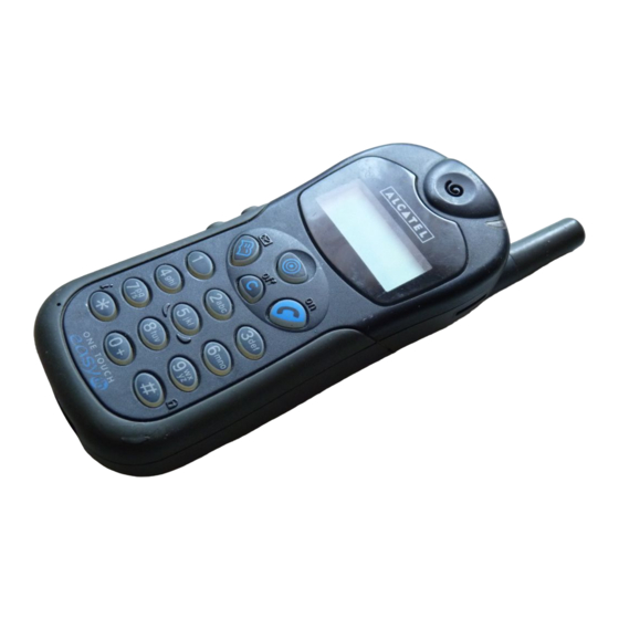
Related Manuals for Alcatel BE1


Summary of Contents for Alcatel BE1
- Page 1 Edition Modification Date Documentation creation by association of the BE1 and BE3 technical documentation in one 09/03/2000 documentation Audio modification on BE3 06/06/2000 Documentation correction on page 19 13/06/2000 Flow chart and visual inspection modification ;Battery test ; new fault codes and a mandatory 05/10/2000 equipment list;...
-
Page 2: Table Of Contents
9.2 Measurements APPENDIX 1 FAULT CODES APPENDIX 2 EQUIPMENT FOR LEVEL 2 REPAIR CENTRE 11/10/00 REPAIR DOCUMENTATION BE1 and BE3 Level 2 BE 1/BE3 2/46 All rights reserved.Passing on and copying of this document, use and communication of its contents are not permitted without... -
Page 3: Level 2 Repair Process
See § 7 Software technical level sticker See § 9 Final test 09/10/00 REPAIR DOCUMENTATION BE1 and BE3 Level 2 BE 1/BE3 3/46 All rights reserved.Passing on and copying of this document, use and communication of its contents are not permitted without... -
Page 4: Test & Visual Inspection
Check the aspect of the rear casing and the antenna Humidity sticker : a humidity sticker is present on some BE1 terminals on the shielding that can be seen on the rear casing side, without openning the handset . Check the state of... - Page 5 • Measure the Thermistor value between pin 4 and pin 6 for Lithium battery (the Thermistor value must be 100 k? at 25 °C) 09/10/00 REPAIR DOCUMENTATION BE1 and BE3 Level 2 BE 1/BE3 5/46 All rights reserved.Passing on and copying of this document, use and communication of its contents are not permitted without...
- Page 6 If these measurements are OK : plug the battery on a good handset, put it on a charger and check the charge icon animation. 09/10/00 REPAIR DOCUMENTATION BE1 and BE3 Level 2 BE 1/BE3 6/46 All rights reserved.Passing on and copying of this document, use and communication of its contents are not permitted without...
- Page 7 Switch on the handset again , if the product asks for the date and hour , the handset must be sent to a LEVEL 3 repair centre. 09/10/00 REPAIR DOCUMENTATION BE1 and BE3 Level 2 BE 1/BE3 7/46 All rights reserved.Passing on and copying of this document, use and communication of its contents are not permitted without...
-
Page 8: Disassembly Of The Product
MULTI-PRODUIT REPAIR DOCUMENTATION L 05/10/2000 BE1/BE3 Ref: Dir:/data/RAFT/DATA_ALCATEL/doc/ 00000 8 / 46... - Page 9 No specific tool is required to remove the antenna ,just hand-unscrew it . MULTI-PRODUIT REPAIR DOCUMENTATION L 05/10/2000 BE1/BE3 Ref: Dir:/data/RAFT/DATA_ALCATEL/doc/ 00000 9 / 46...
- Page 10 Use pliers to remove the J 300( antenna switch) protection MULTI-PRODUIT REPAIR DOCUMENTATION L 05/10/2000 BE1/BE3 Ref: Dir:/data/RAFT/DATA_ALCATEL/doc/ 00000 10 / 46...
- Page 11 Place the product on the plastic positionning tool(positon 2) . Remove the 2 black screws . MULTI-PRODUIT REPAIR DOCUMENTATION L 05/10/2000 BE1/BE3 Ref: Dir:/data/RAFT/DATA_ALCATEL/doc/ 00000 11 / 46...
- Page 12 Remove the 5 yellow screws MULTI-PRODUIT REPAIR DOCUMENTATION L 05/10/2000 BE1/BE3 Ref: Dir:/data/RAFT/DATA_ALCATEL/doc/ 00000 12 / 46...
- Page 13 Disassemble the front casing and the MMI board from the other part of the product (shielding, radiodigital board and rear casing) MULTI-PRODUIT REPAIR DOCUMENTATION L 05/10/2000 BE1/BE3 Ref: Dir:/data/RAFT/DATA_ALCATEL/doc/ 00000 13 / 46...
- Page 14 Remove the 3 grey screws MULTI-PRODUIT REPAIR DOCUMENTATION L 05/10/2000 BE1/BE3 Ref: Dir:/data/RAFT/DATA_ALCATEL/doc/ 00000 14 / 46...
- Page 15 Remove the 2 white screws MULTI-PRODUIT REPAIR DOCUMENTATION L 05/10/2000 BE1/BE3 Ref: Dir:/data/RAFT/DATA_ALCATEL/doc/ 00000 15 / 46...
- Page 16 Remove the upper shielding and check it. Be aware of the positionning pin guide. MULTI-PRODUIT REPAIR DOCUMENTATION L 05/10/2000 BE1/BE3 Ref: Dir:/data/RAFT/DATA_ALCATEL/doc/ 00000 16 / 46...
- Page 17 Remove the Radiodigital board and check it . Be aware of the positionning pin guide . MULTI-PRODUIT REPAIR DOCUMENTATION L 05/10/2000 BE1/BE3 Ref: Dir:/data/RAFT/DATA_ALCATEL/doc/ 00000 17 / 46...
- Page 18 OK clean them . WARNING: For all modifications and repair on radiodigital board use the postionning tool ref : 17010061 it avoids the antenna contact damage (J 301) MULTI-PRODUIT REPAIR DOCUMENTATION L 05/10/2000 BE1/BE3 Ref: Dir:/data/RAFT/DATA_ALCATEL/doc/ 00000 18 / 46...
- Page 19 Remove the lower shielding , check it , if it is not OK change it . Be aware of the positionning pin guide . Check the mechanical state of the rear casing if it is scratched change it . MULTI-PRODUIT REPAIR DOCUMENTATION L 05/10/2000 BE1/BE3 Ref: Dir:/data/RAFT/DATA_ALCATEL/doc/ 00000 19 / 46...
-
Page 20: Hardware Upgrading
MULTI-PRODUIT REPAIR DOCUMENTATION L 05/10/2000 BE1/BE3 Ref: Dir:/data/RAFT/DATA_ALCATEL/doc/ 00000 20 / 46... - Page 21 MULTI-PRODUIT REPAIR DOCUMENTATION L 05/10/2000 BE1/BE3 Ref: Dir:/data/RAFT/DATA_ALCATEL/doc/ 00000 21 / 46...
- Page 22 MULTI-PRODUIT REPAIR DOCUMENTATION L 05/10/2000 BE1/BE3 Ref: Dir:/data/RAFT/DATA_ALCATEL/doc/ 00000 22 / 46...
- Page 23 MULTI-PRODUIT REPAIR DOCUMENTATION L 05/10/2000 BE1/BE3 Ref: Dir:/data/RAFT/DATA_ALCATEL/doc/ 00000 23 / 46...
-
Page 24: Repair
REPAIRS This describes the LEVEL 2 repairs that can be done without any diagnosys equipment 09/10/00 REPAIR DOCUMENTATION BE1 and BE3 Level 2 BE 1/BE3 24/46 All rights reserved.Passing on and copying of this document, use and communication of its contents are not permitted without... - Page 25 Handsfree problem Check J 904, the rear connector Change the faulty element 09/10/00 REPAIR DOCUMENTATION BE1 and BE3 Level 2 BE 1/BE3 25/46 All rights reserved.Passing on and copying of this document, use and communication of its contents are not permitted without...
- Page 26 CAUTION Before sending the products to a LEVEL 3 repair centre, make sure that you have done every hardware upgrading. 09/10/00 REPAIR DOCUMENTATION BE1 and BE3 Level 2 BE 1/BE3 26/46 All rights reserved.Passing on and copying of this document, use and communication of its contents are not permitted without...
-
Page 27: Assembly Of The Product
MULTI-PRODUIT REPAIR DOCUMENTATION L 05/10/2000 BE1/BE3 Ref: Dir:/data/RAFT/DATA_ALCATEL/doc/ 00000 27 / 46... - Page 28 Place the rear casing on the plastic positionning tool ( position1 ) Place the lower shielding in the rear casing . Be aware of the positionning pin guide . MULTI-PRODUIT REPAIR DOCUMENTATION L 05/10/2000 BE1/BE3 Ref: Dir:/data/RAFT/DATA_ALCATEL/doc/ 00000 28 / 46...
- Page 29 Place the radiodigital board in the lower shielding. Be aware of J 904 , J 301 , and the positionning pin guide . MULTI-PRODUIT REPAIR DOCUMENTATION L 05/10/2000 BE1/BE3 Ref: Dir:/data/RAFT/DATA_ALCATEL/doc/ 00000 29 / 46...
- Page 30 Place the upper shielding . Be aware of the positionning pin guide . MULTI-PRODUIT REPAIR DOCUMENTATION L 05/10/2000 BE1/BE3 Ref: Dir:/data/RAFT/DATA_ALCATEL/doc/ 00000 30 / 46...
- Page 31 Place the upper shielding with 2 white screws ; shift the shielding towards J 904 . MULTI-PRODUIT REPAIR DOCUMENTATION L 05/10/2000 BE1/BE3 Ref: Dir:/data/RAFT/DATA_ALCATEL/doc/ 00000 31 / 46...
- Page 32 Screw the 3 grey screws ; respect the order of screwing as shown as above MULTI-PRODUIT REPAIR DOCUMENTATION L 05/10/2000 BE1/BE3 Ref: Dir:/data/RAFT/DATA_ALCATEL/doc/ 00000 32 / 46...
- Page 33 Ionize the MMI board ; be aware of the display MULTI-PRODUIT REPAIR DOCUMENTATION L 05/10/2000 BE1/BE3 Ref: Dir:/data/RAFT/DATA_ALCATEL/doc/ 00000 33 / 46...
- Page 34 Be aware there is no dust on the glass of the front casing : ionize it . Assemble the MMI board with the front casing + keypad . Be aware of the earpiece contacts . MULTI-PRODUIT REPAIR DOCUMENTATION L 05/10/2000 BE1/BE3 Ref: Dir:/data/RAFT/DATA_ALCATEL/doc/ 00000 34 / 46...
- Page 35 Assemble the rear casing + the radiodigital board to the MMI board + keypad . be aware of the good position of the volume keys . MULTI-PRODUIT REPAIR DOCUMENTATION L 05/10/2000 BE1/BE3 Ref: Dir:/data/RAFT/DATA_ALCATEL/doc/ 00000 35 / 46...
- Page 36 Place the yellow screws ; respect the order of screwing as shown above . MULTI-PRODUIT REPAIR DOCUMENTATION L 05/10/2000 BE1/BE3 Ref: Dir:/data/RAFT/DATA_ALCATEL/doc/ 00000 36 / 46...
- Page 37 Place the 2 black screws . MULTI-PRODUIT REPAIR DOCUMENTATION L 05/10/2000 BE1/BE3 Ref: Dir:/data/RAFT/DATA_ALCATEL/doc/ 00000 37 / 46...
- Page 38 Screw the antenna as shown above . Check the SWITCH ON of the handset . MULTI-PRODUIT REPAIR DOCUMENTATION L 05/10/2000 BE1/BE3 Ref: Dir:/data/RAFT/DATA_ALCATEL/doc/ 00000 38 / 46...
-
Page 39: Stickers
If the 2D bar code is not readable , you can enter the references manualy For this , use the file named : BE_SAV enter the references in the fields and for the commercial reference type :3DS-SAV . 09/10/00 REPAIR DOCUMENTATION BE1 and BE3 Level 2 BE 1/BE3 39/46 All rights reserved.Passing on and copying of this document, use and communication of its contents are not permitted without... - Page 40 , as the software has been upgraded (unless the upgrade software is the same as the previous software) A sticker indicating the software technical level must be sticked on the rear casing : Software technical Level 09/10/00 REPAIR DOCUMENTATION BE1 and BE3 Level 2 BE 1/BE3 40/46 All rights reserved.Passing on and copying of this document, use and communication of its contents are not permitted without...
-
Page 41: Customization Software Downloading
The customization software runs under WINDOWS 95 • For customization the interface box must be plugged in POSITION 2 on ACKSYS box • Under the screen PROGRAM MANAGER click on TELE BE1 Exx_xx or TELE BE3 Exx_xx • Read the DATAMATRIX code with the “... -
Page 42: Functionnal Test
• Cosmetic aspect of the handset, the stickers state on the rear casing • Switch on the handset • Welcome message (see « BE1 or BE3 software documentation ») • The display and keypad backlighting • Functionning of all the keys(bip and display ) •... -
Page 43: Appendix 1 Fault Codes
APPENDIX 1 FAULT CODES 09/10/00 REPAIR DOCUMENTATION BE1 and BE3 Level 2 BE 1/BE3 43/46 All rights reserved.Passing on and copying of this document, use and communication of its contents are not permitted without authorization... - Page 44 No Fault Found Corrosion problem Only if corrosion is the cause of the return in after sale. 09/10/00 REPAIR DOCUMENTATION BE1 and BE3 Level 2 BE 1/BE3 44/46 All rights reserved.Passing on and copying of this document, use and communication of its contents are not permitted without...
-
Page 45: Appendix 2 Equipment For Level 2 Repair Centre
APPENDIX 2 EQUIPMENT FOR LEVEL 2 REPAIR CENTRE 09/10/00 REPAIR DOCUMENTATION BE1 and BE3 Level 2 BE 1/BE3 45/46 All rights reserved.Passing on and copying of this document, use and communication of its contents are not permitted without authorization... - Page 46 • GO/NOGO tester • Computer for ACKSYS equipment • Software for stickers printing 09/10/00 REPAIR DOCUMENTATION BE1 and BE3 Level 2 BE 1/BE3 46/46 All rights reserved.Passing on and copying of this document, use and communication of its contents are not permitted without...
Need help?
Do you have a question about the BE1 and is the answer not in the manual?
Questions and answers