Table of Contents
Advertisement
Quick Links
Advertisement
Table of Contents

Related Manuals for Altrad Belle DX 1000HT


Summary of Contents for Altrad Belle DX 1000HT
- Page 1 BELLE 870/90002/0 HSS2015 (F04A) 01/20 1000HT Operators Manual...
-
Page 2: Table Of Contents
Contents CONTENTS PAGE NUMBER EC DECLARATION OF CONFORMITY ..............................3 INTRODUCTION ....................................... 6 WARNING ...................................... 6 Serial Numbers..................................7 - 9 MACHINE DESCRIPTION General......................................10 Standard Operation ..................................10 Danger Zone ....................................10 Main Components Locations .................................11 Operator Station Components..............................12 Instrument Panel .................................. - Page 3 Contents CONTENTS PAGE NUMBER OPERATING INSTRUCTIONS Starting the Engine ..................................37 Travel Preparation ..................................38 ROPS (Roll Over Protection Structure) ............................38 Parking ......................................39 Drive Controls ....................................39 Beacons ....................................... 40 Articulation Lock ................................... 41 Gradients ...................................... 42 Manoeuvering the Dumper ................................43 Skip Control Levers ..................................
-
Page 4: Introduction
Altrad Belle Dealers are trained and equipped for the purpose of advising users on any special problems arising as a result of local conditions, and are able to call on the Technical Staff at Altrad Belle Service department for advice. -
Page 5: General
Moving earth, gravel, ballast and rubble on construction sites and other suitable work sites. Any other use is not deemed suitable for this dumper. Altrad Belle will not liable for any damage or injury resulting from any use other than outlined above. The operator will be liable. -
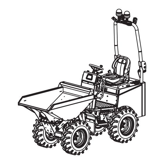
Page 6: Main Components Locations
Machine Description MAIN COMPONENT LOCATIONS Figure 1 F. ROPS (Roll Over Protection Structure) A. Skip G. Warning (Amber) Beacon B. Wheel / Tyres H. Seatbelt (Green) Beacon (Optional) C. Steps J. Worklights (Optional) D. Hand Rails E. Engine (under Seat Pan) -
Page 7: Operator Station Components
Machine Description OPERATOR STATION COMPONENTS Figure 2 A. Instrument Panel G. Emergency Stop Button B. Drive Lever (Forward / Neutral / Reverse) H. Horn J. USB Port C. Steering Wheel D. Seat K. Smartphone Holder E. Dumper Skip Control Levers L. -
Page 8: Instrument Panel
Machine Description INSTRUMENT PANEL Figure 3 A. Indicator Switch (Road Kit only) B. Hazard Lights Switch (Road Kit only) C. Main Beam / Headlights Switch (Road Kit only) D. Side Lights Switch (Road Kit only) E. Work Lights Switch (Optional) F. -
Page 9: Console Switches
Machine Description CONSOLE SWITCHES The switches on the console each have a graphic to explain the function of the switch. Before you operate the machine, ensure you understand the function of the switch. The switches will either be a 2-position or 3-position rocker switch. The switches each have a backlight - the graphic will illuminate when the ignition switch of the side lights are in the ‘ON’... -
Page 10: Ignition Switch
Machine Description HAZARD LIGHTS SWITCH Two Position Rocker Switch This switch operates the Hazard Lights functions. Postion A = Hazard Lights ON Position B =Hazard Lights OFF WORK LIGHTS SWITCH Two Position Rocker Switch This switch operates the Work Lights functions. Postion A = Work Lights ON Position B = Work Lights OFF GREEN BEACON SWITCH (ROAD KIT ONLY) -
Page 11: Static Dimensions
Technical Data STATIC DIMENSIONS... - Page 12 L - Discharge distance front (lowered/raised) 520 / 380mm M - Dumper body tip angle 81° N - Departure angle 38° STATIC DIMENSIONS - WITH OPTIONAL EQUIPMENT DX 1000HT with DX 1000HT with Model Narrow Wheels Wheel Spacers - Overall length 3165mm...
-
Page 13: Turning Circle
Technical Data TURNING CIRCLE Model DX 1000HT Model DX 1000HT A - Turning circle of dumper body (radius) 2637mm C - Steering angle 39.7° B - Turning circle of tyres (radius) 2524mm D - Body oscillation angle 15° PERFORMANCE Model DX 1000HT Max. -
Page 14: Capacities
Technical Data CAPACITIES Model DX 1000HT Skip - Water 280 Ltr Skip - Water 400 Ltr Skip - Water 500 Ltr Fuel Tank 35 Ltr Engine Oil Tank 3.4 Ltr Hydraulic Oil Tank 18 Ltr Hydraulic System 28 Ltr OPERATING GRADIENT... -
Page 15: Steering System
Technical Data STEERING SYSTEM Model DX 1000HT Design Hydraulic Power Steering Steering mode Danfoss HYDRAULICS Model DX 1000HT Hydraulic pump displacement 11cc 30 ltr/min Control valve 2 - Mono Block Max. service pressure 140 bar Hydraulic oil cooler Combi Rad TYRE SIZES &... -
Page 16: Safety Instructions
It is the responsibility of the operator to ensure that he/she fully understands how to operate this equipment safely. If you are unsure about the safe and correct use of the dumper, consult your supervisor or Altrad Belle. -
Page 17: Operating The Machine
Safety Instructions OPERATING THE MACHINE • ENSURE the operator has had adequate training prior to use, is familiar with all controls and knows how to safely switch the dumper OFF before it is switched ON trained and assessed in accordance with an operator competance scheme •... -
Page 18: Public Roads
Safety Instructions PUBLIC ROADS • ALWAYS observe the applicable rules and regulations for the area in which you are travelling. It is the operator’s repsonsibility to ensure these are followed. • It is illegal to use a steering wheel knob when travelling on the public road. The use of this may cause serious injury or death. •... -
Page 19: Fuel
NEVER • ALWAYS use genuine Altrad Belle replacement parts. Use of non-genuine replacement parts may affect the performance and safety of the machine. This may also voide the Warranty. Genuine Altrad Belle replacement parts can be purchased online at www.Altrad-Belle247.com... -
Page 20: Weather Conditions
Safety Instructions WEATHER CONDITIONS • Lightning can kill! DO NOT use the dumper if there is lightning in the area. • Rain can alter the condition of the worksite surface area. ALWAYS be aware of the condition of the surface before and during operation of the dumper adapt your travelling speed to the prevailing surface conditions. -
Page 21: Risk Assessment
Safety Instructions RISK ASSESSMENT It is the responsibility of the operator to ensure that the dumper is used in a safe manner, taking into account all aspects of the worksite and working conditions on and around the worksite. The following are given as a guide to be taken into account when the risk assesment is made. There may be others factors that need to taken into consideration also. -
Page 22: Safety Decals
Safety Instructions SAFETY DECALS Figure 6 A - Forward / Neutral / Reverse Lever Decal G - Articulation Area Warning Decal B - Seatbelt Warning Decal H - Lifting Point Decal C - Diesel Level Decal J - Skip Crush Zone Decal D - Skip Controls Decal K - Orange Beacon Decal E - Tyre Pressure / Wheel Nut Torque Decal... - Page 23 Safety Instructions SAFETY DECALS A - Forward / Neutral / Reverse Lever Decal Instructions on how to drive the dumper. F = Forward, R = Reverse, N = Neutral. B - Seatbelt Warning Decal WARNING - always wear a seabelt whist driving or operating the dumper. C - Diesel Level Decal Highlights the position of the diesel level gauge.
- Page 24 Safety Instructions SAFETY DECALS Figure 7 A - Fan Warning Decal B - Hydraulic Oil Lecel Decal C - Isolator Decal D - Radiator Warning Decal E - Diesel Fill Decal F - Engine Oil Decal G - Gradient Safety Decal H - General Safety Decal J - No Lifting Point Decal K - Cylinder Lock Warning Decal...
- Page 25 Safety Instructions SAFETY DECALS SAFETY DECALS A - Fan Warning Decal WARNING - fast moving fan that poses a risk of crushing. B - Hydraulic Oil Level Decal Indicates the position of the Hydraulic Oil Gauge which shows the level of Hydraulic Oil within the tank. C - Isolator Decal Instructions on how to isolate the battery (See page 33) D - Radiator Warning Decal...
-
Page 26: Operating Conditions
Operating Instructions OPERATING CONDITIONS The dumper has been designed to be operated in ambient temperatures between +40 °C (+104 °F) and -20 °C (-4 °F) Observing these temperature ranges will help to prolong the dumper’s service life. OPERATING IN COLD CLIMATES When the temperature is below freezing (0°C), hydraulic oils and engine oils become thicker and must be warmed up before full machine operation can be safely commenced. -
Page 27: Before Starting The Engine
Operating Instructions BEFORE STARTING THE ENGINE ENSURE WARNING NEVER operate the dumper without this in place. Before the starting the engine to operate the dumper, you must ENSURE the following steps are taken:- • ALWAYS let other bystanders and personnel know you are starting up, do not start until every one is clear of the machine. •... -
Page 28: Entering & Leaving The Operator Station
Operating Instructions ENTERING & LEAVING THE OPERATOR STATION ENSURE the dumper is stationary and parked correctly on stable, level ground before attempting to enter WARNING the operator station. • ALWAYS use the handrails and footsteps provided to enter the dumper operator station (see Figure 9). •... -
Page 29: Operator Seat
Operating Instructions OPERATOR SEAT ALWAYS position the seat so the operator can reach the dumper controls without stretching. WARNING NEVER alter the position of the seat whilst the dumper is moving. Before sitting down on the seat, ensure the seat pan is closed and locked. The seat can be adjusted to suit the operators requirements. -
Page 30: Seat Belt
Operating Instructions SEAT BELT NEVER operate the dumper with the seat belt unbuckled. If you do not wear your seat belt you may be WARNING thrown from the machine resulting in serious injury or even death • ENSURE the seat belt is not twisted once fastened. •... -
Page 31: Stopping The Engine
Operating Instructions STOPPING THE ENGINE ENSURE the dumper is stationary and parked correctly on stable, level ground before attempting to stop CAUTION the engine. 1. ENSURE the drive lever is in the neutral position. 2. Allow the engine to idle for 1-3 minutes. 3. - Page 32 Operating Instructions TRAVEL PREPARATION ALWAYS observe the applicable rules and regulations for the area in which you are travelling. It is the WARNING operator’s repsonsibility to ensure these are followed. TRAVELLING ON PUBLIC HIGHWAYS Before travelling on public roads, the following must be carried out:- 1.
- Page 33 Operating Instructions PARKING ENSURE the dumper is stationary and parked correctly on stable, level ground before attempting to enter WARNING the operator station. NOTE:- If parking the machine on a gradient is unavoidable, place wheel chocks under the wheels to ensure that the dumper will not roll away by itself (Also see Page 42) 2.
- Page 34 Operating Instructions BEACONS ALWAYS observe the applicable rules and regulations for the area in which you are travelling before CAUTION operating the beacon. It is the operator’s repsonsibility to ensure these are followed. • Care MUST be taken when using a beacon on the machine. When the beacon is in the operating position, the total height of the machine is increased.
- Page 35 Operating Instructions ARTICULATION LOCK Before transporting the machine or performing maintenance ALWAYS ensure that the articulation lock WARNING is in the transport position. TRANSPORT POSITION The articulation lock is designed to prevent the dumper from moving during lifting, transportation or whilst any service or maintenance procedures are being carried out.
- Page 36 Operating Instructions GRADIENTS ENSURE WARNING NEVER operate the dumper without this in place. The stability of the dumper will be severely affected when operating on a gradient. Extra care must be taken by the operator to ensure the safety of themselves and other personnel in the area. by the assessment.
- Page 37 Operating Instructions MANOEUVRING THE DUMPER DRIVING FORWARDS ALWAYS accelerate smoothly and slowly when driving a loaded dumper forward. If you accelerate fast or with jerky movements, the load may fall or the machine may become unstable. ENSURE that your route is clear of obstacles and be aware of any personnel present in the vicinty of the where the dumper is being operated.
- Page 38 Operating Instructions SKIP CONTROL LEVERS ENSURE the operator has read and understands the manual before operating the dumper skip control WARNING levers. WARNING NEVER operate the controls from outside the operator station. TIPPING THE DUMPER SKIP 1. Drive the dumper to the where the load is to be discharged. Ideally this would be positioned on stable and level ground.
- Page 39 Operating Instructions LIFTING THE MACHINE ALWAYS ensure the lifting equipment being used is suitable for the lifting the dumper. Using WARNING inadequate or damaged equipment could cause serious injury or even death! Before attempting to the lift the dumper, the following must be carried out:- •...
- Page 40 Operating Instructions TRANSPORTING THE DUMPER WARNING The transport contractor and driver are responsible for the safe transit of the dumper. LOADING THE DUMPER • ENSURE the transport vehicle is of adequate size. Dimensions and weights of the dumper can be found in the Technical Data section (See page 16 - 21) •...
- Page 41 Operating Instructions TYING DOWN THE DUMPER The tie down points are also highlighted with a decal - see below. 1. Position the dumper in a suitable area of the transport vehicle. 2. Engage the articulation lock to stop any unwanted movement (See page 41) 3.
- Page 42 Operating Instructions MOVING A DISABLED DUMPER If the dumper becomes disabled, it must be made safe and lifted onto a suitable transport vehicle to be taken to a location where it can be repaired. Moving a disabled machine without following the correct procedures will damage parts of the hydraulic system. If possible, the disabled machine will be repaired where it stands.
- Page 43 Operating Instructions MOVING A DISABLED DUMPER RECOVERY If the dumper becomes disabled, it can be towed, but the rear brakes will need to be released before doing so. The dumper must only be towed short distances and must not travel in excess of 1.2mph (2kmh) The hydraulic system will not function with the engine being switched off.
- Page 44 Operating Instructions REFUELLING WARNING DIESEL ONLY! DO NOT use petrol in this dumper! Operating the dumper on low fuel levels can sometimes allow air to enter the fuel system, this may cause a loss or reduction of power. To prevent this, always refuel when the fuel guage is showing low fuel level. Refuelling the dumper at the end of each working period will help to prevent condensation forming of the walls of the fuel tank.
Need help?
Do you have a question about the DX 1000HT and is the answer not in the manual?
Questions and answers