
Related Manuals for WiT WT901B


Summary of Contents for WiT WT901B
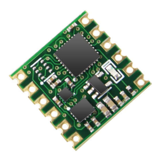
- Page 1 USER MANUAL WT901B Inclinometer Sensor WT901B | manual v0707 | http://wiki.wit-motion.com/english - 1 -...
-
Page 2: Tutorial Link
Technical Support Contact Info Application ● AGV Truck ● Platform Stability ● Auto Safety System ● 3D Virtual Reality ● Industrial Control ● Robot ● Car Navigation ● UAV ● Truck-mounted Satellite Antenna Equipment WT901B | manual v0707 | http://wiki.wit-motion.com/english - 2 -... -
Page 3: Table Of Contents
2.4.3 Baud Rate ..................- 23 - 2.4.4 Data Recording ................- 24 - 2.4.5 Data Playback .................. - 26 - 2.4.6 Standby and Wake Up ..............- 28 - 2.4.7 Placement Direction ..............- 29 - WT901B | manual v0707 | http://wiki.wit-motion.com/english - 3 -... - Page 4 4.3 Raspberry pi ....................- 46 - 4.4 C# ........................- 46 - 4.5 C++ ......................... - 47 - 4.6 Matlab ......................- 47 - 5 IIC Connection ....................... - 48 - WT901B | manual v0707 | http://wiki.wit-motion.com/english - 4 -...
-
Page 5: Introduction
Its strength lies in the algorithm which can calculate three-axis angle accurately. WT901B is an CE standard accelerometer. It is employed where the highest measurement accuracy is required. WT901B offers several advantages over competing sensor: •... -
Page 6: Warning Statement
For proper instrument grounding: use WITMOTION with its original factory-made cable or accessories. For secondary developing project or integration: use WITMOTION with its compiled sample code. WT901B | manual v0707 | http://wiki.wit-motion.com/english - 6 -... -
Page 7: Use Instructions With Pc
Link to WT901B’s demo video 2.1.1 Serial Connection Step 1. Connect the sensor with a serial converter PIN Connection: VCC - TX - RX - GND - GND (When connecting with computer, VCC-5V is recommended.) WT901B | manual v0707 | http://wiki.wit-motion.com/english - 7 -... - Page 8 Step 4. Open the software(Minimu.exe) Data will appear after auto-search finishes Notice: If not successful, please operate manually Choose the com port and baud rate 9600, data will be shown on the software. WT901B | manual v0707 | http://wiki.wit-motion.com/english - 8 -...
-
Page 9: Software Introduction
Factory test For manufacturer internal test only Auto-search Auto searching the sensor Port Com port selection Baud Baud rate selection Type Fixed setting as Normal for WT901B Open Open com port WT901B | manual v0707 | http://wiki.wit-motion.com/english - 9 -... - Page 10 Close Close com port WT901B | manual v0707 | http://wiki.wit-motion.com/english - 10 -...
-
Page 11: Menu Of Configuration
Menu of Configuration Menu of Configuration Button Function Read Config Reading the current configuration Lock Lock the sensor Unlock Unlock the sensor Calibrate Time Calibration time of chip Save Config Save configuration WT901B | manual v0707 | http://wiki.wit-motion.com/english - 11 -... - Page 12 HWT901B) Reset Z-axis Angle Reset Z-axis angle to 0 degree, not available for WT901B in 9-axis algorithm Angle Reference Setting current angle as 0 degree Gyro Auto Calibrate Auto-calibration of gyroscope WT901B | manual v0707 | http://wiki.wit-motion.com/english - 12 -...
- Page 13 Latitude&Longitude data output, only available when the sensor connecting with GPS module, such as WTGAHRS1, WTGAHRS2 GPS IMU PDOP Ground velocity data output, only available when the sensor connecting with GPS WT901B | manual v0707 | http://wiki.wit-motion.com/english - 13 -...
- Page 14 Menu of Port D0 Model Extended port D0 D1 Model Extended port D1 D2 Model Extended port D2 D3 Model Extended port D3 Pulse width Pulse width of PWM Cycle Cycle of PWM WT901B | manual v0707 | http://wiki.wit-motion.com/english - 14 -...
-
Page 15: Calibration
After calibration, the measurement will be accurate. Methods: Step 1. Keep the module horizontally stationary Step 2. Click the accelerometer calibration Step 3. Click the “Start calibration”and wait for 3 seconds Step 4. Click “Complete Calibration” WT901B | manual v0707 | http://wiki.wit-motion.com/english - 15 -... - Page 16 0, 0,1, the X and Y axis Angle is around 0°. After calibration, the X,Y axis Angle is accurate. Note: When putting the module horizontal, there is 1g of gravitational acceleration on the Z-axis. WT901B | manual v0707 | http://wiki.wit-motion.com/english - 16 -...
-
Page 17: 2.3.2 Magnetic Field Calibration
Sensors should be 20CM away from magnetic and iron and other materials Methods: Step 1. Open the Config menu Step 2. Click the magnetic field calibration button. click the “Start calibration” WT901B | manual v0707 | http://wiki.wit-motion.com/english - 17 -... - Page 18 Step 3. Slowly rotate the module 360° around X, Y, Z, 3-axis accordingly WT901B | manual v0707 | http://wiki.wit-motion.com/english - 18 -...
-
Page 19: 2.3.3 Gyroscope Automatic Calibration
The gyroscope calibration is to calibrate the angular velocity, and the sensor will calibrate automatically. It is recommended that the automatic calibration of gyroscopes can be inactivated only if the module rotates at a constant speed. WT901B | manual v0707 | http://wiki.wit-motion.com/english - 19 -... -
Page 20: 2.3.4 Reset Z-Axis Angle
The operation method is to click the "Reset Height" option in the configuration bar. Only available for the module built-in barometer like WT901B, HWT901B, WTGAHRS1, WTGAHRS2 WT901B | manual v0707 | http://wiki.wit-motion.com/english... -
Page 21: Configuration
Taking WT901B as an example, the default output of the module is acceleration, angular velocity, angle, and magnetic field. Notice: If choosing the GPS Original, there will be no other data output. -
Page 22: Output Rate
Reminder: If there being many types of return data and low baud rate of communication, the module will automatically reduce the frequency and output at a maximum allowable output rate. The default baud rate is 9600. WT901B | manual v0707 | http://wiki.wit-motion.com/english - 22 -... -
Page 23: Baud Rate
Note: After the change, the module will no longer output data at the original baud rate. The data will be output only when the baud rate that has been changed is selected on the PC software again. WT901B | manual v0707 | http://wiki.wit-motion.com/english - 23 -... -
Page 24: Data Recording
2.4.4 Data Recording Method are as follows: Step 1: Click “Record” and “Begin” Step 2: Click “Stop” WT901B | manual v0707 | http://wiki.wit-motion.com/english - 24 -... - Page 25 Windows system’s time. The changes in other data is correct. It is highly recommended that data can be pasted to an Excel file. In this way, all data will be shown in order. WT901B | manual v0707 | http://wiki.wit-motion.com/english - 25 -...
-
Page 26: Data Playback
Recorded data playback method: Step 1: Disconnect the sensor Step 2: Click “File” Button and then click “Load” Step 3: Choose the original path of software installation and load the Bin file WT901B | manual v0707 | http://wiki.wit-motion.com/english - 26 -... - Page 27 Step 4: Click “Run” and the Binary file will be playback When playback, the rate can be editable. WT901B | manual v0707 | http://wiki.wit-motion.com/english - 27 -...
-
Page 28: Standby And Wake Up
Wake up: The module enters the working state from the standby state. The module defaults to a working state, in the“Config”of the software, click “Sleep”option to enter the sleep state, click“Sleep”again to release sleep. WT901B | manual v0707 | http://wiki.wit-motion.com/english - 28 -... -
Page 29: Placement Direction
Step 1: Rotate the module 90 degrees around the X-axis Step 2: Place the sensor 90 degrees vertically Step 3: Click “Vertical” as install directions on “Config” menu WT901B | manual v0707 | http://wiki.wit-motion.com/english - 29 -... -
Page 30: Bandwidth
1. The higher rate of bandwidth setting will lead to the higher fluctuation in data waveform. Conversely, the lower rate of bandwidth, data will become more fluent. For example: Bandwidth as 20Hz, Output rate as 10Hz. The waveform is very steady. WT901B | manual v0707 | http://wiki.wit-motion.com/english - 30 -... - Page 31 For example, if the bandwidth setting is 20Hz, retrieval rate as 100Hz, there will be 5 repeating data. If you prefer there is no repeating data, it is required to increase the bandwidth more than 100Hz. WT901B | manual v0707 | http://wiki.wit-motion.com/english - 31 -...
-
Page 32: Restore Factory Setting
2 seconds. The LED is off, and the factory reset operation is completed. Command method: connect the WT901B module and the computer through the USB-TTL module, click the setting tab, and click to restore the default. After restoring the factory settings, power on the module again. (This method needs... -
Page 33: Set Iic Address
16 hexadecimal IIC address and click the “change” button. Reminder: The IIC address of the module will not be changed immediately, and it will take effect when the module restart. WT901B | manual v0707 | http://wiki.wit-motion.com/english - 33 -... -
Page 34: Set Extended Port
2.4.11 Set Extended Port The WT901B module has 4 multiple function extended ports, which can be set to different functions according to the need. Set extended port only when the module connects to the PC software successfully. The extended port supports analog input mode, digital input mode, digital output mode, PWM output mode. - Page 35 In the PWM output mode, the port state data is used to indicate the high level of the PWM, the unit us. WT901B | manual v0707 | http://wiki.wit-motion.com/english - 35 -...
-
Page 36: 6-Axis/ 9-Axis Algorithm
9-axis algorithm: Z-axis angle is mainly calculated and analyzed based on the magnetic field. Z-axis angle will have few drift. The default algorithm of WT901B is 9-axis. If there is magnetic field interference around installed environment, it is recommended to switch to 6-axis algorithm to detect the angle. -
Page 37: Set Alarm Status
10 ° or less than -10 °, the corresponding port will output high level (3.3V). Name Function Output X﹢alarm status Output X- alarm status Output Y﹢alarm status Output Y- alarm status WT901B | manual v0707 | http://wiki.wit-motion.com/english - 37 -... -
Page 38: Use Instructions With Android Phone
Use Instructions with Android Phone For APP configuration introduction, please referring to the Chapter 2.2 APP Installation Install the APK file, give permission of Location and Storage Link to download Android APP WT901B | manual v0707 | http://wiki.wit-motion.com/english - 38 -... -
Page 39: Hardware Preparation
Hardware Preparation Connecting with Android smartphone requires a serial cable and a Type-C converter or OTG converter according to phone’s interface. WT901B | manual v0707 | http://wiki.wit-motion.com/english - 39 -... -
Page 40: Connection
“Choose an APP for the USB device”, which means that the device has been detected. Choose “WitMotion”, “ JUST ONCE” or “ALWAYS” is optional. 2. Only CH340 driver can be detected via WitMotion APP. WT901B | manual v0707 | http://wiki.wit-motion.com/english - 40 -... - Page 41 Step 3. Open APP and choose “9-axis Series” as sensor series WT901B | manual v0707 | http://wiki.wit-motion.com/english - 41 -...
- Page 42 Step 4. Select the baud rate- 9600. WT901B | manual v0707 | http://wiki.wit-motion.com/english - 42 -...
- Page 43 After selection and wait for a few seconds, the data will show automatically. WT901B | manual v0707 | http://wiki.wit-motion.com/english - 43 -...
-
Page 44: Calibration
Step 1. Keep the module horizontally stationary Step 2. Click the “Calibration” menu Step 3. Click the “Acceleration Calibration” and wait for 3 seconds Step 5. Judge the result--confirm if there is 1g on Z-axis acceleration WT901B | manual v0707 | http://wiki.wit-motion.com/english - 44 -... -
Page 45: Magnetic Field Calibration
Step 4. After rotation, click “Magnetic Calibration Finish” Check the result: The Z-axis angle will have fewer drift than before. Notice: If not successful, please stay away from the objective that can create magnetic field interference. WT901B | manual v0707 | http://wiki.wit-motion.com/english - 45 -... -
Page 46: Mcu Connection
Link to sample code instructions demo Notice: There is no sample code provided for Linux or Python system at present. Arduino Download link Arduino UNO3 Demo Link STM32 Download link Raspberry pi Tutorial link DEMO link WT901B | manual v0707 | http://wiki.wit-motion.com/english - 46 -... -
Page 47: Matlab
DEMO link Matlab Receive Sample Code Dataplot DEMO WT901B | manual v0707 | http://wiki.wit-motion.com/english - 47 -... -
Page 48: Iic Connection
IIC Connection The WT901B module can be connected to the MCU through the IIC interface. The connection method is shown in the figure below. Note: 1. In order to connect multiple modules on the IIC bus, the IIC bus of the module is an open-drain output.
Need help?
Do you have a question about the WT901B and is the answer not in the manual?
Questions and answers