Chapters
Table of Contents

Summary of Contents for AFP Imaging IMAGE-VET 70 ACP
- Page 1 250 Clearbrook Road Elmsford, NY 10523 V i s i o n a r y I m a g i n g Installation, Operation & Service Manual Veterinary Diagnostic X-ray Unit With Anatomical Timer Control © AFP Imaging Corp., 2007 P/N 897-000022...
- Page 3 AFP Imaging Corp., © AFP Imaging Corporation, 2007. All information, specifications and illustrations contained herein are subject to change. AFP Imaging Corp. has a company policy of continual development. Therefore, it reserves the right to make changes without prior notice.
- Page 4 ABOUT THIS PRODUCT... Performance The Image-Vet 70ACP X-ray system is designed for use in veterinary dental radiography. It is an AC type X-ray system that houses both the high voltage transformer and tube insert in a compact tubehead assembly. This assembly is supported by a spring loaded articulating arm that is balanced to provide smooth movement and positioning of the tubehead in a variety of positions.
- Page 5 REVISION RECORD Title: Image-Vet 70ACP Installation, Operation & Service Manual Document Number: 897-000022 Revision Effective Date Description August, 2004 Initial Release November, 2004 Full Revision May, 2007 Partial Revision INSPECTION RECORD Inspection Effective Date Description/Notes...
-
Page 6: Table Of Contents
SECTION A: OPERATORS MANUAL Image-Vet 70ACP TABLE OF CONTENTS: WARNINGS 5 - 6 A1.1. Ambient conditions A1.2. Purpose of the equipment A1.3. Improper use A1.4. Protection against radiation A1.5. Compliance with current standards and regulations DESCRIPTION OF THE Image-Vet 70ACP 9 - 10 X-RAY EQUIPMENT A2.1. -
Page 7: A1. Warnings
A1. Warning Symbols & Labelling Pay careful attention to the symbols contained herein and on the equipment. Certain instructions are preceded by Warning! with a triangle at the side. Whenever this symbol appears, carefully read the relevant paragraph before performing any operations. See symbol #2 Definitions of symbols used: Degree of protection when coming directly or indirectly into contact with live electrical parts. - Page 8 Before leaving the operatory, turn the main switch to the “Off” position. The equipment is not liquid-proof. Do not immerse components. The equipment is not suitable for use in the presence of flammable anaesthetic gas based on oxygen and nitrous oxide. WARNING! If electrical equipment which does not comform with local codes for shield- ing and isolation and/or FCC Part 15 of the FCC rules for class A computing...
-
Page 9: A1.1. Ambient Conditions
A1.1. Ambient conditions The place where the equipment is to be installed should satisfy the following conditions: Temperature between 50° and 105° F (10° and 40° C) Relative humidity from 30 to 75% Atmospheric pressure from 700 to 1060 hPa. A1.2. -
Page 10: A1.5. Compliance With Current Standards And Regulations
All instuctions concerning operations during which X-rays are emitted will be preceded by this symbol to remind the user of the precautions to be taken, as recommended by local regulations. General precautions for protection against X-rays. • Operator control X-ray emission from a distance of at least 6 feet from the focal spot of the X-ray. -
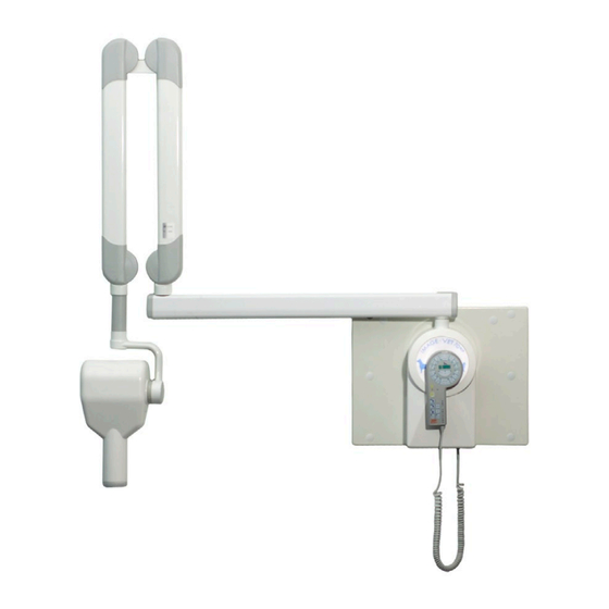
Page 11: Description Of The Image-Vet 70Acp X-Ray Equipment
Description of the Image-Vet 70ACP X-ray equipment EXPOSE Description of the X-ray Description of the hand held system X-Mind control unit X-ray Tubehead/Tubehead Display, Film sensitivity (1 to 9) or Assembly X ray tubehead selected (A or B) Dial, angulation Patient’s jaw size selection Timer/Wall-mount pivot assembly Warning light, X-ray emissions... - Page 12 Double-jointed scissors arm X-ray tubehead with collimator This is a double-jointed arm which carries the The X-ray tubehead is self-contained and due X-ray tubehead. It can be extended or retracted to its operating characteristics, the exposure and moved up and down while keeping the tube- time can be reduced so that less radiation head balanced in the position it has reached.
-
Page 13: A2.1. Nameplates
A2.1. Nameplates (1) X-ray tubehead nameplate The name plate is located on the back of the tubehead. The following details are given on the name plate: · Manufacturer · Name of equipment · Serial number · Tube insert number · Specifications ·... -
Page 14: A3. Use Ofthe Image-Vet 70Acp
A3. Basic applications of the Image-Vet 70ACP A3.1. Basic patient position The patient should be positioned on the table in whatever position that is appropriate for the radiograph to be taken. A3.2. Positioning the X-ray tubehead assembly Position the tubehead by moving the double-jointed scissors arm so as to bring the collimator into contact with the patient’s skin at the point where the radiograph is to be made. -
Page 15: A3.3. Turning On The X-Mind Control
A3.4. Factory settings Factory settings are determined when the equipment is installed and can only be modified by AFP Imaging Corp. authorized technicians. Always prepare before exposure with appropriate protective shields, aprons or equivalent devices to protect from... - Page 16 Typical Wall Mounting Typical Mobile Mounting...
-
Page 17: A3.5. Setting The Exposure Time
A3.5. Setting the exposure time To set the radiation exposure time, the following operations must be carried out: X-Mind Hand Held Selector · Press the key corresponding to the type of dog tooth being radiographed. Otherwise press the key for upper or lower cat jaw radiographs or the ones for paw or exotic radiographs. -
Page 18: Exposure Time Chart
Selecting film sensitivity with the key: NOTE: A setting of 2 - 3 for film sensitivity is a good range for Kodak Insight (F) speed film OR the EVA-Vet Digital Imaging System. A setting of 6 - 8 for film sensitivity is a good range for Kodak Ultra-Speed (D) speed film. - Page 19 Radiograph-film correction chart Sensitivity Standard Variation coefficient 0.500 - 50 % 0.630 - 37 % 0.800 - 20 % 1.000 1.250 + 25 % 1.600 + 60 % 2.000 + 100 % 2.500 + 150% 3.200 +220% The above chart shows the amount of exposure time variation for the different film sensitivity values NOTE: All upper and lower tooth selections are for dogs only.
-
Page 20: A4. Developing The Film
A4. Film developing A4.1 Automatic Processor Automatic film processors designed for processing dental films with RP type chemicals (such as the AFP 810 Plus or 810 Basic) control all of the processing parameters (such as temperature, time, washing and drying) automatically. When set up and maintained properly, they will develop the images with very little attention required by the operator. -
Page 21: A5. Cleaning And Disinfection
A5. Cleaning and disinfection A5.1. Cleaning and disinfection in structions The external surfaces and parts of the equipment must be cleaned and disinfected. Instruments. Clean with warm water and mild detergent Use soft, non-abrasive, disposable paper or (optional), using a soft cloth. Disinfect with a cloth for cleaning and disinfection. -
Page 22: A6. Maintenance
A6. Maintenance Preventive maintenance is described in Section B3 under Installation . Any servicing should be carried out by qualified service personnel. A6.1. Periodic maintenance Every year: Perform radiation emission testing as required by your local codes. Check the labels located on the control panel and X-ray tube for condition. Check the exterior of the equipment for damage that may reduce protection against radiation. - Page 23 E 009 No power to the X-ray tubehead. Turn the equipment off and then on again. If the trouble persists call your dealer’s service dept. E010 The X-ray tubehead is short circuited or the supply and neutral wires are reversed or system is failing the software check for tube current.
-
Page 24: Specifications
A7. Technical Specifications The X-ray tubehead has been certified by the manufacturer to be in compliance with FDA regulations as per 21 CFR SUBCHAPTER J as amended. Periodic compliance testing of this equipment may be required by local governmental agencies. There are no regulatory performance standards for veterinary X-ray equipment. -
Page 25: A8. Fuses
Transformer insulation Mineral Oil bath Exposure time interval 1 s exposure - 30 s pause Min. focus to skin distance 7.9 in (20 cm) Diameter of X-ray beam < 2.36 in (6 cm) (when it reaches the skin at end of cone) Cooling Convection Radiation leakage at 1 m... -
Page 26: Section B: Installation Manual
SECTION B: INSTALLATION MANUAL Image-Vet 70ACP (ONLY FOR AFP CORP-AUTHORIZED SERVICE TECHNICIANS) TABLE OF CONTENTS: PRE-INSTALLATION STAGE B1.1. Packing B1.1.1. Re-shipment and storage B1.2. Tools needed for installation (not included in tool kit) B1.3. Pre Installation requirements Steel Wall Plate (Photo) Steel Wall Plate instructions 28-29 B1.4. -
Page 27: B1. Pre-Installation Stage
B1. Pre installation Installation Procedure Outline - Image-Vet 70ACP Determine location for X-Mind Control / wall support, input power supply line (120/230 volts/15 amps) and extension arms with respect to the examination table. Decide if internal wall wiring or external surface wiring will be used. 3) Mount X-Mind Control / wall support, extension arm and scissors arm. -
Page 28: B1.1. Packing
B1.1. Packing Packing container dimensions: 42 in X 20.5 in X 11.5 in (107 x 52 x 29 cm) Max. weight: 88 Lbs (40 kg) Contents: Technical documentation and warranty certificate Atlas and "Getting Started" video X-Mind timer / wall mount X-ray tubehead Extension arm Accessory kits... -
Page 29: B1.2. Tools Needed For Installation (Not Included In Tool Kit)
B1.2. Tools needed for B1.3. Pre Installation installation requirements Multi-meter Determine if the large Wall Mounting Plate will Tape measure be necessary. If not, the X-Mind Timer Assembly Spirit level used to mount the X-ray support arms and Power drill and a set of drill bits for tubehead must be firmly secured to the wall. -
Page 30: Steel Wall Plate Instructions
STEEL WALL MOUNTING PLATE PN 9992700112 IMAGE VET 70ACP X-MIND TIMER/WALL MOUNT STEEL WALL MOUNTING PLATE INSTALLATION KIT CONTENTS: 1 pc P/N 897-000007 Steel Wall Mounting Plate, White 6 pcs P/N 897-000008 1” DIA, Hole Plug, Plastic White 1 pc P/N 897-000162 Instructions, Template for Steel Wall Mount 3 pcs... - Page 31 Reference installation, Section B2.1. Steel Wall Plate dimensions are 20” wide x 15 ¾” high x 1 ¼” thick. Wall Mounting bolt hole pattern is on standard 16” centers horizontally and 7” centers vertically. The hollow, steel box design and construction allows for internal (hidden) wiring and interconnection of components.
-
Page 32: B1.4. Electrical Requirements
B1.4. Pre Installation electrical requirements. Refer to wiring diagrams included with the unit Installation method and materials must be in compliance with local electrical codes. Determine if supply wiring will be internal to the wall or surface mounted. Confirm that installation is for 120/230 VAC operation. -
Page 33: B2.1.1. Installing Onto Wall-Mount Plate
B2.1.1. X-Mind Timer Assembly direct or on optional Wall Mount Plate First, determine if the X-Mind Timer Assembly will be mounted directly on the wall or if site condi- tions require the wall mount plate. This will be determined by the existing wall construction and load bearing ability. -
Page 34: B2.1.2. Extension Arm
B2.1.2. Extension arm 1. Insert the extension arm into the arm support block which is an integral part of the wall support plate. NOTE: You must keep the arm at right angles to the plate to be able to insert the shaft into the bush placed inside the support. -
Page 35: B2.1.3. Double-Jointed Scissors Arm
B2.1.3. Double-jointed scissors arm WARNING! IMPORTANT! The two main parts of the scissors arm are held together with a tie band. The band MUST NOT BE REMOVED until the two ends of the arm are fixed to the wall extension arm (already secured) and to the X ray tube head. -
Page 36: B2.1.4. Tubehead
Note: perform steps 7 and 8 after tubehead installation. Remove the scissors arm safety clamp and check the ergonomics of its movement again, otherwise adjust the friction mechanism again (1) and/or the tension of the arm balance springs (see section B4.3.3.). Assemble the front covers of the extension arm, packaged separately with the small parts. -
Page 37: B2.2. Electrical System
B2.2. Electrical system - Refer to wiring diagram on page 36. B2.2.1. Electrical output to tubehead L - BLACK OR BROWN supply wire N - WHITE OR BLUE neutral wire YELLOW/GREEN ground wire End of scissors arm Internal Connections ( - L is for center ring) ( - N is for outer ring) Above is a view looking into the end of the scissors arm where the tubehead is inserted. -
Page 38: B2.2.2. Wiring The Control Unit
ELECTRICAL WIRING - SINGLE TUBE OPERATION ONLY Route the hot and neutral wires (See diagram B2.2.2. Wiring the control unit below) coming from the scissors arm to termi- Connect the incoming line voltage to the nals 10 and 16 on the M2.1 terminal strip. It is terminal block (M3) as indicated: important that the LINE or HOT (black) wire goes L - BLACK OR BROWN line/hot wire... -
Page 39: B2.2.3. Control Unit Configuration And Functions
B2.2.3. Control unit confi guration and functions JUMPER DESCRIPTION POSITION MEANING Hand-held control Position 2 Hand-held control Remote control Position 1 Remote exposure control Not Used Main line frequency Closed 60 Hz (60 or 50 Hz) Open 50 Hz Maximum number of Open tubeheads Main line voltage... -
Page 40: B2.2.4. Conditioning The X-Ray Tube
B2.2.4. Conditioning the X-ray tube Once installation has been completed, the X-ray tube is to be conditioned to eliminate any impurities which may have built up on the anode during storage or shipment. To do this, proceed as follows: Set a time of 0.02 s. Allow the tube to emit radiation at least 15 times. -
Page 41: B3. Preventive Maintenance
B3. Preventive maintenance B3.1. Checks AFP recommends that the following maintenance procedures be carried out periodically. It is good practice to perform these procedures when the equipment is installed and then once every year thereafter. IMPORTANT CAUTION: TO BE PERFORMED ONLY BY A QUALIFIED SERVICE TECHNICIAN Should any trouble be found when these checks are made, consult the “Cor- rective maintenance”... -
Page 42: B3.1.4 Measuring High Voltage
B3.1.4 Measuring high voltage KVp value is defined as the stationary value of high voltage applied to the tube which settles on load after preheating time. KVp value is measured by a non-invasive instrument, with accuracy of over 2%, at the nominal value of line voltage. -
Page 43: B4. Corrective Maintenance
B4. Corrective maintenance B4.1. Service test CAUTION: TO BE PERFORMED ONLY BY A QUALIFIED SERVICE TECHNICIAN Press and hold the “TEST” button (e) while turning on the system to enable the “Service Test” mode. The display (a) indicates the type of test pro cedure that has been selected - refer to paragraph A2. - Page 44 WARNING! This operation will modify the voltage used for “time compensation”. Therefore, only change the setting when using properly set and accurate instruments. · Set the digital voltmeter to a range > 200 Vac. Attach the test leads to the supply terminals of the control unit.
-
Page 45: B4.2. Trouble-Shooting Guide
TROUBLE PROBABLE CAUSES POSSIBLE SOLUTIONS When the equipment is turned on, no No power delivered between L and N in The line switch IS open indicator light comes on connector M2 in the control unit Faulty power supply The supply wires are improperly connected The main switch is turned to position 0 Move the switch to position “l”... - Page 46 TROUBLE PROBABLE CAUSES POSSIBLE SOLUTIONS Fault message E 011 appears Hardware problems in the power supply. Turn the equipment off and then on again. If the trouble persists, replace the main PC board Fault message E012 appears Improper operation Press any key and then perform the operation in the correct manner Fault message E 013 appears The audible warning device does not work...
-
Page 47: B4.2.1. Diagnosing Problems: Tubehead Or Arm Wiring
B4.2.1. Diagnosing problems: tubehead or arm wiring short-circuited or open Having removed the tubehead, use a multi-meter to check the equipment for electrical continuity and/or for the presence of short-circuits between the wall mount plate and the concentric connector in the support bushing of the tubehead. If shorts are found or the electrical conductors are broken or interrupted, replace the supply cable, the electrical connector(s) or possibly the tubehead. -
Page 48: B4.3.2 Adjusting The Extension Arm Friction Mechanism
B4.3.2 Adjusting the extension arm friction mechanism 1. Remove the small front extension arm cover, working carefully. 2. Adjust the friction mechanism (1) using a 4 mm allen wrench while checking the rotation of the scissors arm. NOTE: The purpose of this friction mechanism is to prevent the scissors from becoming detached, so it must not be loose. -
Page 49: B4.3.3 Adjusting The Scissors Arm Balance
B4.3.3 Adjusting the scissors arm balance • Adjusting the second arm Proceed as follows to adjust the scissors arm: Adjusting the friction (for small corrections - picture A) Put the arm in a horizontal position; remove the plastic coordinator covers. This must be done carefully to avoid breaking the covers. - Page 50 B4.3.3 Adjusting the scissors arm balance • Adjusting the first arm If the first arm also needs to be adjusted: Adjusting the friction (for small corrections - picture A) Close the arm scissors arm; remove the plastic co-ordinator covers. This must be done carefully to avoid breaking the covers.
-
Page 51: B5. Parts
B5. Parts B5.1. Electrical DESCRIPTION COVER, COMPLETE 897-CV546132 SCREW FOR COVER (2) E2100110500 MAIN ON/OFF SWITCH E4291415900 HAND-HELD CONTROLLER WITH CABLE 897-ZZ0145061 HAND-HELD CONTROLLER CABLE 897-PC1908270 TIMER BOARD (120V) 897-ZZ0145062 TIMER BOARD (230F) 897-ZZ0145060 FUSE (F4) T10A SLOW BLOW (120V) 897-FU0001007 FUSE (F4) T6.3A SLOW BLOW (230V) 897-FU0001014... -
Page 52: B5.2. Electro-Mechanical
B5. Parts B5.2. Electro-Mechanical DESCRIPTION SCISSORS ARM 9992700610 STANDARD EXTENSION ARM - 31.5” (80CM) 9992700603 OPTIONAL MEDIUM EXTENSION ARM - 23.625” (60 CM) 9992700602 OPTIONAL SHORT EXTENSION ARM - 11.813” (30 CM) 9992700601 TUBEHEAD (120V) 9992700611 TUBEHEAD (230V) 9992702011 KIT, WALL MOUNTING PLATE 9992700112 GROUND CLIP (FOR TUBEHEAD) 897-000137... -
Page 53: B6. Mobile Stand
B6. Mobile Stand P/N 9992700110 Assembly and Maintenance Instructions Description The AFP Image-Vet 70ACP Mobile Stand is constructed of steel and coated with abrasion resistant epoxy paint. It consists of a rolling base assembly and vertical support column. Four wheels attached to the base allow free movement of the system between locations. - Page 54 Assembly (Cont’d) Main Unit Using the allen key provided, fasten the vertical support column to the base assembly with the bolt and lock-washer provided, making sure that the locator roll pin is inserted into both the base and the support column. Refer to Figure 2 for the following: Insert the cable from the scissors arm through the bushing (1) at the top of the vertical support column and out through the hole (TIP - Fold the cable over first, then insert the folded part down through the bushing to lend rigidity).
- Page 55 47.3" (120.2 cm) Figure 3 Retainer clip for attaching the tubehead 31.5" to the scissors 30" (80 cm) (76.2 cm) arm. Figure 2 4.38" (11 cm) 25.6" (65 cm) 10" (25.4 cm) 25.6" (65 cm) 6.75" (17 cm) 3.13" (8 cm) 73.9"...
- Page 56 V i s i o n a r y I m a g i n g AFP Imaging Corporation, 250 Clearbrook Road, Elmsford, NY 10523 914.592.6100 © Copyright AFP Imaging Corp., 2008...
Need help?
Do you have a question about the IMAGE-VET 70 ACP and is the answer not in the manual?
Questions and answers
How is the image moved from the Image-Vet 70 ACP
The AFP Imaging IMAGE-VET 70 ACP transfers the image using either film or a digital sensor. The system supports 9 levels of film or sensor sensitivity, allowing for image capture based on the selected exposure settings.
This answer is automatically generated