
Related Manuals for Diablo DSP-7LP


Summary of Contents for Diablo DSP-7LP
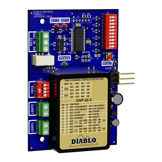
- Page 1 User Manual DSP-22-2 Low Power, Dual Channel Vehicle Detector with Support for the Free Exit Probe Pros Who Know Trust Diablo DSP-22-2_MAN_E 12/10/2020 Page 1 of 25...
-
Page 2: Table Of Contents
Contents Figures ..................................3 Introduction ............................4 Functional Data ............................... 5 Electrical Data ................................. 6 Environmental Data ..............................6 Mechanical Data ..............................7 Features and Functions ........................... 8 Detector Reset ................................ 8 Channel 1 – Enable / Disable (DIP Switch 9) ......................8 Channel 1 –... -
Page 3: Figures
Figures Figure 1: Product Views ..............................4 Figure 2: Physical Dimensions ............................7 Figure 3: Loop Installation ............................19 Figure 4: Saw Cut for Home Run Exit and Chiseled Corner for Home Run Exit ............19 Figure 5 Typical Free Exit Probe Installation ......................20 DSP-22-2 User Manual Page 3 of 25 DSP-22-2_MAN_E... -
Page 4: Introduction
The DSP-22-2 detector is intended to be a two-channel detector that can work with both inductive loops as well as the new Diablo Control Free Exit Probe. The detector is powered by a high-performance 8-bit microcontroller that does not skimp on performance. The DSP-22-2 detector has a small footprint and was designed to directly plug into many DoorKing operators. -
Page 5: Functional Data
Functional Data Sensitivity: Four sensitivities for each channel are user selectable. Channel 1: S1 DIP Switch Sensitivity .32% ΔL/L Low .16% ΔL/L Medium Low .08% ΔL/L Medium High .04% ΔL/L High Channel 2: S1 DIP Switch Sensitivity .32% ΔL/L Low .16% ΔL/L Medium Low .08% ΔL/L Medium High .04% ΔL/L High... -
Page 6: Electrical Data
Electrical Data Loop Inductance: 20 microhenries to 1500 microhenries (including lead-in inductance). Not all frequency settings are available at inductances below 30 microhenries. Operating Voltage: 14 volts to 27 volts DC Solid State Output Rating: Maximum Output Current: 250 milliamps Maximum Pull-Up Voltage: 30 volts Maximum Voltage Drop Across Active Output: 0.3 volts Relay Output Rating:... -
Page 7: Mechanical Data
Mechanical Data Mounting Position: Housing Material: Lexan Detector Size: 4.300 inches (High) x 2.950 inches (Wide) x .820 inches (Deep) 109.22 mm (High) x 74.93 mm (Wide) x 20.83 mm (Deep) Figure 2: Physical Dimensions DSP-22-2 User Manual Page 7 of 25 DSP-22-2_MAN_E... -
Page 8: Features And Functions
2. Features and Functions Detector Reset When any of the DIP switches are changed, the reset button is pressed, or power is cycled to the detector, the detector will perform a reset. The reset event will last for two seconds while the detector initiates any changes and waits for all systems to stabilize. -
Page 9: Channel 1 - Normal Sensitivity / Sensitivity Boost (Dip Switch 3)
Channel 1 – Normal Sensitivity / Sensitivity Boost (DIP Switch 3) Each channel of the detector has a user selectable feature that increases the sensitivity of the detector after initial detection. This feature is most often used to allow a detector to have a lower starting sensitivity and then increase it after a vehicle has been detected. -
Page 10: Channel 2 - Normal Sensitivity / Sensitivity Boost (Dip Switch 6)
raise the sensitivity. For those situations where the detector is overly sensitive, lower the sensitivity one level at a time until the desired performance is obtained. Remember that semi-trucks look much smaller than a car. So, do not set or test the sensitivity using a passenger vehicle if semi-truck traffic will be seen over the loop. The factory default is low (DIP switch 1 OFF and DIP switch 2 OFF). -
Page 11: Channel 2 - Loop / Probe (Dip Switch 8)
When Channel 2 is in the pulse mode of operation, the pulse generated by the output will be 250 milliseconds long. There are slight differences between the probe pulse mode (DIP switch 8 ON) and the pulse mode (DIP switch 7 ON). So, they will be explained individually. If DIP switch 7 is ON and DIP switch 8 is OFF, the way the pulse mode operates is commonly referred to as Pulse on Entry. -
Page 12: Indicators
If there are suspicions that loops are interacting, change one of the detector’s frequency settings for the suspect channel so that their inherent frequencies are sufficiently different as to no longer interact. If the loops are the same size and number of turns, setting one channel to high and the other channel to low will provide the maximum frequency separation. - Page 13 Detect The LED is on constantly when a vehicle is detected. Open Loop When the detector senses that the loop is open, or the inductance is too high, the LED will flash once every two seconds repeatedly, for the duration of the fault. If the fault is corrected the LED will display the appropriate Prior Fault indication.
- Page 14 activated the LED shall display the flicker indication. The flicker display is a very fast flashing at a lower level of brightness. In the Pulse mode this occurs when the entry pulse has been generated and the vehicle is still over the sensor.
-
Page 15: Installation
Installation General Rules and Best Practices for Inductive Loops Before beginning the installation, it is important to make that the loop you are about to use is appropriate for this installation. Here are some general rules and best practices that will help you ensure that the loop you use will have the desired performance and a long life. -
Page 16: Detector Installation
9. The approximate inductance of the lead-in cable can be calculated using a value of .22 µH per foot for lead-in cable. 100’ x .22 µH = 22 µH of inductance in 100’ of lead-in cable. 10. The ratio of loop inductance to lead-in inductance should be 2 to 1 for a well-designed installation. Since the vehicle to be detected can only influence the loop inductance, letting the lead-in inductance get close to the loop inductance will effectively lower the sensitivity of the loop. -
Page 17: Loop Installation
Wiring: Attach the loops to the appropriate loop screw terminals. Wire nuts should never be used at any point in the loop circuit itself. All loop connections should be crimped or use screw terminals at a minimum and soldered for best long-term reliability. Special attention should be paid to ensure that the loop wires remain tightly twisted together. - Page 18 The number of turns to use in a loop is dependent on the size of the loop and length of the lead-in. Rather than dive into all of the calculations to arrive at a value, we will just give you a table of safe values based on the number of square feet in the loop (length times width in feet).
-
Page 19: Figure 3: Loop Installation
BACKER ROD PIECE LOOP WIRE CUTS DETAIL B DETAIL A Figure 3: Loop Installation Figure 4: Saw Cut for Home Run Exit and Chiseled Corner for Home Run Exit DSP-22-2 User Manual Page 19 of 25 DSP-22-2_MAN_E... -
Page 20: Free Exit Probe Installation
The loop wire should be installed as a continuous piece of wire from the detector to the loop, all of the turns in the loop, and back to the detector. Remember to make allowance for shrinkage in the wire length when the portion of the wire not in the roadway surface is twisted. - Page 21 Side Detection Zone Placement NOTE: When the roadway is greater than 11 feet wide requiring a greater detection zone you have the option to add a second Free Exit Probe to the opposing side of the roadway. The probes must be wired in series. DSP-22-2 User Manual Page 21 of 25 DSP-22-2_MAN_E...
-
Page 22: Troubleshooting
4. Troubleshooting No Power LED The first step is to ensure that the correct model of the detector is being used for the installation. Ensure that the wiring is correct, and the correct voltage is being used. Use a meter to measure the voltage applied to the detector. The voltage must be between 14 volts and 27 volts If the correct voltage is applied and the power LED is not on, replace the detector. -
Page 23: Detect Led Flashes At The Same Time As The Power Led Every Two Seconds
If a loop is connected to the correct screw terminals of the detector, disconnect the loop and using an ohmmeter, check the resistance of the loop circuit. If the resistance is below 0.2 ohms there is a short in the loop circuit. The resistance will typically be 0.5 ohms to 1.5 ohms. -
Page 24: Detect Led Will Not Come On With A Vehicle Present
during loop installation, physical stressing of the wire due to movement (crossing of expansion joints or asphalt that has slowly moved or deformed), wires moving in the saw slot due to poor loop sealant encapsulation, foreign objects embedded in the saw slot, and poor electrical connections in the loop circuit. The best way to check for any of these issues is to use a megohmmeter (commonly referred to as a megger). -
Page 25: Detect 1 And Detect 2 Leds Flash Back And Forth
If the red LED illuminates, then perhaps the sensitivity setting is too low. There are many variables in determining overall sensitivity: loop size, number of turns, loop lead-in, percent coverage, etc. In most cases, a sensitivity setting of medium high is the correct setting. However, to compensate for some unusual loop geometries, this setting may be inadequate.
Need help?
Do you have a question about the DSP-7LP and is the answer not in the manual?
Questions and answers