Yaesu FT-710 Operation Manual
Hide thumbs
Also See for FT-710:
- Manual (75 pages) ,
- Reference manual (26 pages) ,
- Service update information (3 pages)
Table of Contents
Advertisement
Quick Links
Advertisement
Table of Contents

Related Manuals for Yaesu FT-710


Summary of Contents for Yaesu FT-710
- Page 1 FT-710 Operation Manual...
- Page 3 About this Manual The FT-710 is a leading-edge transceiver with a number of new and exciting features, some of which may be unfamiliar to you. In order to gain the most enjoyment and operating efficiency from the FT-710, we recommend that you read this manual in its entirety, and keep it handy for reference as you explore the many capabilities of this new transceiver.
-
Page 4: Table Of Contents
Table of Contents General Description ........4 CURSOR ..........22 FIX ............23 Safety Precautions .........6 3DSS ............23 Accessories & Options ........8 MULTI ............23 Installation and Interconnections ....9 EXPAND ........... 24 Antenna Considerations ........9 SPAN ............24 Antenna Connections ......... 9 SPEED ............. - Page 5 Specifications ..........106 Index ............108 Checking the CW Memory Contents ..... 52 On-The-Air CW Message Playback ....52 YAESU LIMITED WARRANTY ....110 TEXT Memory ..........53 Display the Certifications of Text Memory Storage ........53 FCC and CANADA ........112 Text Message Programming ......
-
Page 6: General Description
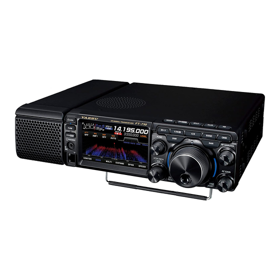
High-brightness TFT full-color display with touch-panel functionality The FT-710 is equipped with a 4.3-inch full-color TFT display. Operating functions, including the receiving band noise and signal interference reduction tools, are graphically displayed. Even while involved in rig- orous operations, such as DXpeditions and contests, the operator may instantly grasp the status of each function. - Page 7 DNR (Digital Noise Reduction) by DSP digital processing The incorporated digital noise reduction circuit may be set to the optimal working algorithm by varying the 15 step parameters according to the noise type. NOTCH feature can eliminate an unwanted heterodyne, and the DNF feature can instantly attenuate multiple heterodyne signals When interfering beat signals are present in the receiver passband, the IF NOTCH feature can significant- ly eliminate a narrow portion of the passband and remove the interfering signal.
-
Page 8: Safety Precautions
Safety Precautions Note beforehand that the company shall not be liable for any damages suffered by the customer or third parties in using this product, or for any failures and faults that occur during the use or misuse of this prod- uct, unless otherwise provided for under the law. - Page 9 Do not allow metallic objects such as wires Refrain from using headphones and ear- and water to get inside the product. phones at a loud volume. This may result in fire, electric shock and equip- Continuous exposure to loud volumes may result ment failure.
-
Page 10: Accessories & Options
Accessories & Options Supplied Accessories External Speaker SP-40 Hand Microphone SSM-75E DC Power Cord Spare Fuse (25A) • Operation Manual • World Map • Sticker Available options • Hand Microphone (equivalent to the supplied microphone) SSM-75E • Reference Microphone • Dual Element Microphone M-100 •... -
Page 11: Installation And Interconnections
Construct the antenna and coaxial cable, or use a suitable antenna tuner, to maintain the impedance presented to the FT-710 antenna connector for an SWR of 1.5 or less. Careful preparation of the antenna and/or tuner will permit maximum performance, and protect the transceiver from damage. -
Page 12: Microphone, Headphone, Key, Keyer And Fh-2 Connections
Microphone, Headphone, Key, Keyer and FH-2 Connections ① DOWN ② ③ ④ MIC GND ⑤ ① ⑥ ⑦ ⑧ ⑧ FAST (as viewed from front panel) φ3.5mm External Speaker Remote Control Keypad SP-40 FH-2 (option) Key-up voltage is approximately +5.0V DC, and key-down current is approximately 3mA. -
Page 13: Linear Amplifier Interconnections
Linear Amplifier Interconnections Be sure that both the FT-710 and VL-1000 are turned OFF, and then follow the installation recommendations contained in the bellow illustration. • VL-1000 Linear Amplifier Interconnections • Refer to the VL-1000 Operating Manual for details regarding amplifier operation. -
Page 14: Display Connections
Operate the transceiver from a remote location. Use the optional LAN unit “SCU-LAN10” to connect the FT-710 to a LAN or the Internet, then use the PC control software that can be downloaded from the Yaesu website. In addition to the basic remote operation of the transceiver, the LAN unit supports moni- toring the various scope displays, so you can operate comfortably. -
Page 15: Aess (Acoustic Enhanced Speaker System)
• The AESS is designed to function optimally with the included speaker “SP-40”. It will not perform properly with other speakers. • When moving or transporting the FT-710, remove the SP-40 to prevent it from falling off. SP-40 connections The SP-40 can be mounted on either the left or right side of the transceiver. -
Page 16: Rear Panel
REM/ALC ter characters. By plugging the FH-2 Remote Control Keypad into EXT-DISPLAY this jack, direct access to the FT-710 CPU is pro- DVI-D connector for connecting an external moni- vided for control functions of the contest memory tor. keying, and also frequency and function control. -
Page 17: Ssm-75E Microphone Switches
SSM-75E Microphone Switches PTT Switch Switches Transmit/Receive. Press to transmit and release to receive. DWN / UP Key MUTE The [UP]/[DWN] keys may also be used to manual- ly scan the frequency upward or downward. ● The amount of frequency change depends on the operation mode (default setting: see table below). -
Page 18: Display Indications
Display Indications It operates as an S meter in receive. In transmit, select the desired meter from: PO, COMP, ALC, VDD, ID, and SWR. Displays the current operation mode. In VFO mode, “VFO-A” or “VFO-B” is displayed. In memory mode, the type and chan- nel number of the recalled memory are displayed. -
Page 19: Meter Display
Meter Display Operation MODE Display S-Meter Displays the current operating mode. When touched the operation mode selection screen is displayed. Touch the desired operation mode to select it. RF power Output When the meter display screen is touched, the transmit meter selection screen is shown (the default setting is “PO”). -
Page 20: Frequency Display (Vfo-A)
Frequency Display (VFO-A) Frequency Display (VFO-B) Displays the transmit and receive frequencies of Displays the transmit and receive frequencies of VFO-A. Press the [A/B] key to switch between VFO-B. Press the [A/B] key to switch between VFO-A and VFO-B, the frequency of VFO-B is VFO-B and VFO-A, the frequency of VFO-A is displayed. -
Page 21: Operation Of The Display [Func] Knob
Operation of the display [FUNC] knob Displays the multiple functions that may be operated when the [FUNC] knob is pressed. Normally, it is recommended to adjust the level of the spectrum scope with the [LEVEL] knob. The last used function is recalled when the [FUNC] knob is pressed. Therefor you can easily call up and then set a function by turning the [FUNC] knob. -
Page 22: Filter Function Display
Filter Function Display Displays the passband status of the Digital filter. The operation of WIDTH, SHIFT, NOTCH, CONTOUR etc. can be observed. Passband status of DSP filter (SHIFT, WIDTH) State of NOTCH State of CONTOUR SSB Mode CW Mode RTTY Mode PSK/DATA Mode DSP filter bandwidth Touch the filter display to reveal and check the setting value of the last used function from SHIFT, WIDTH, NOTCH,... -
Page 23: Important Receiver Settings
• Normally, select “AMP1”. lections until you are thoroughly familiar with the • The IPO can not only attenuate the input sig- performance of the FT-710. nal but also improve the intermodulation char- acteristics. It is most effective to operate the IPO first, and then use the ATT if the signal is still too strong. -
Page 24: Information Displayed On The Scope Screen
The frequency span is shown on the horizontal X axis, the vertical Y axis depicts the signals and their strengths, and the time is represented on the receding Z axis. The FT-710 operator can intuitively grasp the band and signal conditions at any instant. -
Page 25: Fix
• FIX • 3DSS To use Fixed Mode, enter the start frequency of the Switch between the 3DSS display and the waterfall scope. display. The display will change each time it is touched: 3DSS type Display area start frequency Marker* (Reception Frequency) Marker* (Transmit Frequency) Current display mode (FIX) Waterfall type... -
Page 26: Expand
• EXPAND • SPEED The display area of the scope screen may be ex- Sets the Scope Display sweep speed. After touch- panded vertically. ing, select the desired speed. Touch to expand the display. Touch again to return to the original. Normal Display SLOW1 : sweep speed Slow... -
Page 27: Set With The Func Knob
Set with the FUNC knob Operate the [FUNC] knob to make the following settings related to the display. LEVEL : Adjust the LEVEL of the scope for the best image on the screen. PEAK : Adjust the color density with respect to the signal level on the scope screen in 5 steps (LV1 to LV5). -
Page 28: Marker
• MARKER • Adjust contrast Displays markers that indicates the position of the Adjust the contrast of the TFT display. current receive and the transmit frequencies in the Press the [FUNC] knob then touch [CONTRAST], spectrum. and then turn the [FUNC] knob to adjust the con- Press the [FUNC] knob then touch [MARKER] to trast. -
Page 29: Other Display Settings
Other display settings • Screen Saver • Inputting the Call Sign A Screen saver, to prevent burning of the TFT Registered call signs names, and characters can screen will operate after a set time, if no trans- be displayed on the opening screen when the ceiver function is operated. - Page 30 5. Touch [ENT] to save the new setting and exit to normal operation. About TFT Displays FT-710 utilizes a TFT liquid-crystal display. Although TFT liquid-crystal displays are made using very precise technology, they are prone to de- velop dead pixels (dark dot) or pixels that are always on (bright dot). Please understand that such phenomena do not constitute product defects or malfunctions.
- Page 31 Memo...
-
Page 32: Front Panel Controls & Switches
TUNE [FUNC] knob to the point where the transmitter is quickly activated by your voice, without back- This is the ON/OFF switch for the FT-710 Automatic ground noise causing the transmitter to activate. Antenna Tuner. • Adjusts the VOX Delay Time Press the [TUNE] key briefly to activate the antenna tuner. -
Page 33: Adjusts The Vox Anti-Trip Sensitivity
Simply fold the stand forward to raise the front of the trans- MIC GND ceiver, and fold it back against the bottom case to lower the front of the FT-710. FAST... -
Page 34: Step Mch
DSP interference removal functions Pressing this knob momentarily, exchanges the SHIFT, WIDTH, NOTCH, CONTOUR and APF. These functions can be operated individually for VFO-A and VFO-B, on each operating band. 1. SHIFT IF SHIFT permits moving the Digital filter passband higher or lower, without changing the pitch of the in- coming signal, and thus reduce or eliminate interfer- ence. -
Page 35: Shift
1. SHIFT The figure below is a conceptual diagram of WIDTH. 1. Press the [STEP • MCH / ] knob. IF BANDWIDTH 2. Rotate the [STEP • MCH / ] knob to select “SHIFT”, then press the [STEP • MCH / ] knob. -
Page 36: Contour
4. CONTOUR 5. APF The APF function can be operated individually for VFO-A and VFO-B, on each operating band (The set- tings are common to VFO-A and VFO-B, and each op- erating band). 1. Press the [STEP • MCH / ] knob. -
Page 37: Dnr (Digital Noise Reduction)
BAND (Operating Band Selection) Touch the display to select Press the [BAND] key, the operation band selection screen appears on the display, so touch the desired band. When you touch it, the band will be confirmed for about 1 second and then return to the operating screen. -
Page 38: Vmi (Vfo Mode Indicator)
NAR (Narrow) This key is used to set the DSP (digital) IF filters to Narrow bandwidth. Press this key again to return the bandwidth control to the WIDTH system. • Change the bandwidth by pressing the NAR key 1. Press the [FUNC] knob. 2. -
Page 39: Rf Gain/Sql
RF GAIN/SQL RF (default setting) The RF Gain control provides manual adjustment of the gain levels for the receiver RF and IF stag- es, to account for noise and signal strength con- ditions at the moment. [RF GAIN/SQL] knob is normally in the fully clockwise position. -
Page 40: Zin/Spot
LEVEL], and rotating the [FUNC] knob. [CLAR] key. SPLIT • RX Clarifier A powerful capability of the FT-710 is its flexibility If the transmit frequency of the contact station in Split Frequency operation using the VFO-A and deviates, this receiver clarifier frequency can VFO-B frequency registers. -
Page 41: Tx Clarifier
• TX Clarifier The transmit frequency can be changed without The FT-710 includes an effective IF Noise Blanker, moving the receive frequency of the transceiver. which can significantly reduce noise caused by au- Normally, the clarifier is used to move only the re- tomotive ignition systems. -
Page 42: Voice Communications (Ssb And Am)
Voice Communications (SSB and AM) When transmitting in SSB or AM mode The FT-710 transmit audio circuit can be set to the optimum operating level by individually adjusting the input and output gains of the microphone amplifier. The AMC (Automatic Microphone Gain Control) regulates the microphone audio so that distortion does not oc- cur, even if excessive audio is input. -
Page 43: Speech Processor
Speech Processor ● Setting of maximum transmission output The maximum transmit power can be set for each The FT-710 Speech Processor is designed to of the HF Bands, the 50MHz band and the AM increase “talk power” by increasing the average mode. -
Page 44: Parametric Microphone Equalizer
Parametric Microphone Equalizer The FT-710 includes a unique Three-Band Parametric Microphone Equalizer that provides precise, in- dependent control over the low, mid and treble ranges in the voice waveform. One group of settings may be utilized when the AMC or speech processor is Off, and an alternate group of settings when the AMC or Speech Processor is On (SSB mode only). - Page 45 Parametric Gain 3-Stage Parametric Equalizer Adjustments (Speech Processor: “OFF”) PRMTRC EQ1 FREQ (Low) “100” (Hz) - “700” (Hz) / OFF Center Frequency PRMTRC EQ2 FREQ (Mid) “700” (Hz) - “1500” (Hz) / OFF PRMTRC EQ3 FREQ (High) “1500” (Hz) - “3200” (Hz) / OFF PRMTRC EQ1 LEVEL (Low) “-20”...
-
Page 46: Voice Memory
Voice Memory The Voice Memory capability of the FT-710 may be used to store and replay often repeated messages. The Voice Memory includes five memories. The Voice Memory may be operated from the Display Panel, or from the optional FH-2 Remote Control Keypad, which plugs into the rear panel REM jack. -
Page 47: Record The Received Audio
Record the received audio You can record and play the received audio on the SD memory card. Record and play of the received audio may be operated from the Display Panel, or from the optional FH-2 Remote Control Keypad, which plugs into the rear panel REM jack. •... -
Page 48: Adjustable Receiver Audio Filter
Adjustable Receiver Audio Filter The FT-710 incorporates an adjustable receiver audio filter, that affords precision control of the lower and upper audio ranges independently. 1. Press the [FUNC] knob. 2. Select [CW SETTING] for CW mode and [RA- DIO SETTING] for other modes. -
Page 49: Change The Sound Quality Of The Received Audio
Change the sound quality of the received audio You can change each of the high, mid, and low frequencies of the received audio to your liking. It can be set for each mode. 1. Press the [FUNC] knob. 2. Select [CW SETTING] for CW mode and [RA- DIO SETTING] for other modes. -
Page 50: Using The Automatic Antenna Tuner
SWR at the antenna feed point. • The ATU in the FT-710 is designed to match impedances within the range of 16.5 Ohms to 150 Ohms, cor- responding to an SWR of 3:1 or less on the HF amateur bands (6 m amateur band: 25 Ohms to 100 Ohms, corresponding to an SWR of 2:1 or less). -
Page 51: Cw Mode Operation
● Press [FUNC], then touch [CW SPEED], and rotate the [FUNC] knob to set the de- sired sending speed. ● As shipped from the factory, the FT-710 CW TX/RX is configured for “Semibreak-in” operation. However, using Menu item “CW BK-IN TYPE”, this setup may be changed... -
Page 52: Setting Of The Electronic Keyer
Keyer speed can be adjusted by rotating the The configuration of the Electronic Keyer may be [FUNC] knob. customized for the FT-710. This permits utilization of Automatic Character Spacing (ACS), if desired. Press [FUNC], then touch [CW SPEED], and ro-... -
Page 53: Contest Memory Keyer
Contest Memory Keyer The CW message capability of the FT-710 may be controlled either from the Transceiver Front Panel, or with the optional FH-2 Remote Control Keypad, which plugs into the rear panel REM jack. • Message Memory Five CW memory channels capable of retaining 50 characters each are available (using the PARIS stan- dard for characters and word length). -
Page 54: Checking The Cw Memory Contents
• Checking the CW Memory Contents • On-The-Air CW Message Playback 1. Press the [FUNC] knob. 1. Press the [FUNC] knob. 2. Touch [BK-IN] to turn it “OFF”. 2. Touch [BK-IN] to turn it “ON”. 3. Touch [MONI LEVEL] and then turn the When using FH-2, go to step 4. -
Page 55: Text Memory
MEMORY 4 and MEMORY 5 in factory de- fault. MEMORY 4: DE FT-710 K } MEMORY 5: R 5NN K } 6. Touch the character keys on the display to enter the letters, numbers, or symbols of the desired label. -
Page 56: Checking The Cw Memory Contents
• Checking the CW Memory Contents • On-The-Air CW Message Playback 1. Set the operating mode to CW. 1. Set the operating mode to CW. 2. Press the [FUNC] knob. 2. Press the [FUNC] knob. 3. Touch [BK-IN] to turn it “OFF”. 3. -
Page 57: Fm Mode Operation
FM Mode Operation Repeater Operation Tone Squelch Operation The FT-710 may be operated on 29MHz and The “Tone Squelch” may be activated to keep the 50MHz repeaters. receiver silent until an incoming signal modulated with a matching CTCSS tone is received. The 1. -
Page 58: Data (Ft8 / Rtty / Psk) Operation
• Connecting with a USB cable To connect to a PC using a USB cable, a Virtual COM port driver must be installed on the PC. Visit the Yaesu website http://www.yaesu.com/ to download the Virtual COM port driver and Installation Manual. To USB port Commercially available USB (A-B) cable •... -
Page 59: Ft8 Operation
FT8 operation The multiple settings required for FT8 operation may be set with one touch of [PRESET]. In addition, the FT8 settings can be returned to the prior settings with one touch. 1. Touch the operation mode area, or press the then press the [FUNC] knob. -
Page 60: Rtty Operation
RTTY Operation 1. Before operating with RTTY, set the Menu items in the chart to the below. Setting Menu Available Values (Bold is the default) The shift direction of the RTTY transmit space frequency will be lower than RADIO SETTING the mark frequency. - Page 61 Memo...
-
Page 62: Memory Operation
Memory Operation This key toggles frequency control between VFO and the memory system. The contents of the memory channels can be recalled and used later. • Memory Storage 1. Set the frequency, mode, and status, as de- sired. 2. Press and hold the [V/M ] key. -
Page 63: Recall A Memory Channel Other Than The Last Used Vfo Frequency
• Recall a Memory Channel other than • Memory Groups the last used VFO frequency Memory channels may be listed into as many as six convenient groups, for easy identification Rotate the [STEP • MCH / ] knob and selection. For example: groups for AM BC to select a memory stations, Short-wave broadcast stations, Contest 1. -
Page 64: Erasing Memory Channel Data
• Erasing Memory Channel Data • Labeling Memories The contents written to the memory channel may Alphanumeric labels (“Tags”) may be appended to memory channels, to aid in recollection of the chan- be erased. nel’s use (such as a club name, a location etc.). 1. -
Page 65: Scan Skip Setting
• Scan Skip Setting • 60-Meter (5 MHz) Band (U.S. Version only) The “Frequency display” or “Name display” format may be selected. Memory channels (U.S. version: “5-01” through “5-10”) are pre-programmed, at the factory, with 1. Press and hold the [V/M ] key. -
Page 66: Vfo And Memory Scanning
VFO and Memory Scanning Either the VFO or the memory channels of the FT-710 may be scanned, and the receiver will halt scan- ning on any frequency with a signal strong enough to open the receiver squelch. In the SSB/CW and SSB-based Data modes, the decimal points in the frequency display area will blink and the scanner will slow down (but does not stop). -
Page 67: Programmable Memory Scan (Pms)
Programmable Memory Scan (PMS) To limit scanning (and manual tuning) to a particular frequency range, the Programmable Memory Scan- ning (PMS) feature utilizes nine special-purpose memory pairs (“M-P1L/M-P1U through M-P9L/ M-P9U). The PMS feature is especially useful in helping to observe any operating sub-band limits which apply to your Amateur license class. -
Page 68: Other Functions
Other Functions Band Stack Operation Operation on Alaska Emergency Frequency: The FT-710 employs a triple band-stack VFO se- lection technique that permits storing up to three 5167.5kHz (U.S. Version Only) favorite frequencies and modes onto each band Section 97.401(d) of the regulations governing VFO register. -
Page 69: Screen Capture
The captured date and time will be the file File Name name. y (year), m (month), d (day), h (hour), m (minute), s (second) “Capture” folder Folder structure in SD card FT-710 Capture Data storage MemList location Menu Message PlayList... -
Page 70: Using The Sd Card
4. Touch “OK”, the SD card will be initialized. data can no longer be written or erased. Touch “CANCEL” to cancel the initialization. • Note that Yaesu shall not be liable for any 5. “FORMAT COMPLETED” will be displayed damages suffered as a result of data loss or when initialization is completed. -
Page 71: Saving Memory Data And Setting Menu Data
• Saving Memory data and Setting Menu data The Memory Channel data, and the Setting Menu data can be saved to the SD Card: 1. Press the [FUNC] knob. 5. Enter the file name (maximum 15 characters) 2. S e l e c t [ E X T E N S I O N S E T T I N G ] → [ S D on the file name input screen. -
Page 72: Reading Memory And Set Menu Data
• Reading Memory and Set Menu data • Display the SD Card Information The Memory and Setting Menu data saved on the The memory free space of the SD card may be SD card may be read to the Transceiver. checked: 1. -
Page 73: Setting Menu
Setting Menu The Menu system of the FT-710 provides extensive customization capability. The transceiver functions can be tailored for the most demanding operators. The Setting Menus are grouped into five specific utili- zation categories. Comprehensive settings such as: Transmit & Receive, Interference Reduction, Memory, Scan, etc. - Page 74 Menu Function Available Settings (Default: Bold) RADIO SETTING -20 - 0 - 10 MODE SSB AF TREBLE GAIN -20 - 0 - 10 AF MIDDLE TONE GAIN -20 - 0 - 10 AF BASS GAIN 20 - 300 - 4000 (20msec/step) AGC FAST DELAY 20 - 1000 - 4000 (20msec/step) AGC MID DELAY...
- Page 75 Menu Function Available Settings (Default: Bold) RPT SHIFT(50MHz) 0 - 1000 - 4000 (10kHz/step) ENC/DEC OFF / ENC / TSQ TONE FREQ 67.0 - 100.0 - 254.1 (Hz) MODE PSK/DATA AF TREBLE GAIN -20 - 0 - 10 AF MIDDLE TONE GAIN -20 - 0 - 10 AF BASS GAIN -20 - 0 - 10...
- Page 76 Menu Function Available Settings (Default: Bold) 50 / 100 / 150 / 200 / 250 / 300 / 350 / 400 / 450 / 500 / 600 NAR WIDTH 800 / 1200 / 1400 / 1700 / 2000 / 2400 / 3000 / 3200 / 3500 4000 (Hz) PC KEYING OFF / RTS / DTR / DAKY...
- Page 77 50 / 100 / 200 MAIN STEPS PER REV. DISPLAY SETTING DISPLAY MY CALL Max 12 characters (FT-710) MY CALL TIME OFF / 1 / 2 / 3 / 4 / 5 (sec) FAST / MID / SLOW POP-UP TIME...
- Page 78 Menu Function Available Settings (Default: Bold) YEAR HOUR MINUTE SD CARD MEM LIST LOAD MEM LIST SAVE MENU LOAD MENU SAVE INFORMATIONS FIRMWARE UPDATE FORMAT SOFT VERSION CALIBRATION CALIBRATION RESET MEMORY CLEAR MENU CLEAR ALL RESET...
- Page 79 AGC SLOW DELAY RADIO SETTING Function: Sets the AGC-SLOW DELAY voltage - MODE SSB - decay characteristics for SSB mode. Available Values: 20 - 4000msec AF TREBLE GAIN Default Setting: 3000msec Description: Sets the AGC voltage decay char- Function: Sets the amount of gain in the treble acteristics in 20msec steps after the range of the received audio.
- Page 80 MOD SOURCE NAR WIDTH Function: Selects the transmit audio input jack in Function: Sets the IF BANDWIDTH of the digital the SSB mode. filter when the [NAR] key is pressed in Available Values: MIC / USB / REAR / AUTO LSB/USB mode.
- Page 81 AGC SLOW DELAY RADIO SETTING Function: Sets the AGC-SLOW DELAY voltage - MODE AM - decay characteristics for AM mode. Available Values: 20 - 4000msec AF TREBLE GAIN Default Setting: 4000msec Description: Sets the AGC voltage decay char- Function: Sets the amount of gain in the treble acteristics in 20msec steps after the range of the received audio.
- Page 82 MOD SOURCE RADIO SETTING Function: Selects the transmit audio input jack in - MODE FM - the AM mode. Available Values: MIC / USB / REAR / AUTO AF TREBLE GAIN Default Setting: AUTO Description: Function: Sets the amount of gain in the treble MIC: Audio is input from the MIC jack on the range of the received audio.
- Page 83 AGC SLOW DELAY MOD SOURCE Function: Sets the AGC-SLOW DELAY voltage Function: Selects the transmit audio input jack in decay characteristics for FM mode. the FM mode. Available Values: 20 - 4000msec Available Values: MIC / USB / REAR / AUTO Default Setting: 1500msec Default Setting: AUTO Description: Sets the AGC voltage decay char-...
- Page 84 RPT SHIFT(28MHz) RADIO SETTING Function: Sets the RPT offset frequency on the - MODE PSK/DATA - 28MHz band. Available Values: 0 - 1000kHz AF TREBLE GAIN Default Setting: 100kHz Description: The RPT offset frequency can be set Function: Sets the amount of gain in the treble at 10kHz increments between 0kHz range of the received audio.
- Page 85 AGC SLOW DELAY MOD SOURCE Function: Sets the AGC-SLOW DELAY voltage Function: Selects the transmit audio input jack in decay characteristics for PSK/DATA the DATA mode. mode. Available Values: MIC / USB / REAR / AUTO Available Values: 20 - 4000msec Default Setting: AUTO Default Setting: 1500msec Description:...
- Page 86 NAR WIDTH RADIO SETTING Function: Sets the IF BANDWIDTH of the digital - MODE RTTY - filter when the [NAR] key is pressed in DATA mode. AF TREBLE GAIN Available Values: 50 / 100 / 150 / 200 / 250 / 300/ 350 / 400 / 450 / 500 / 600 / Function: Sets the amount of gain in the treble 800 / 1200 / 1400 / 1700 /...
- Page 87 AGC SLOW DELAY RPTT SELECT Function: Sets the AGC-SLOW DELAY voltage Function: Sets the PTT control for the RTTY decay characteristics for RTTY mode. transmit signal. Available Values: 20 - 4000msec Available Values: OFF / RTS / DTR / DAKY Default Setting: 1500msec Default Setting: OFF Description: Sets the AGC voltage decay char-...
- Page 88 AGC SLOW DELAY CW SETTING Function: Sets the AGC-SLOW DELAY voltage - MODE CW - decay characteristics for CW mode. Available Values: 20 - 4000msec AF TREBLE GAIN Default Setting: 1500msec Description: Sets the AGC voltage decay char- Function: Sets the amount of gain in the treble acteristics in 20msec steps after the range of the received audio.
- Page 89 RPTT SELECT CW FREQ DISPLAY Function: Sets the PTT control for the CW trans- Function: Sets the PITCH frequency offset. mit signal. Available Values: DIRECT FREQ / PITCH OFFSET Available Values: OFF / RTS / DTR / DAKY Default Setting: PITCH OFFSET Default Setting: OFF Description: Sets the displayed frequency offset Description:...
- Page 90 NUMBER STYLE CW SETTING Function: Selects the contest number “Cut” for- - KEYER - mat for an imbedded contest number. Available Values: 1290 / AUNO / AUNT / A2NO / KEYER TYPE A2NT / 12NO / 12NT Default Setting: 1290 Function: Selects the desired keyer operation Description: Abbreviates numbers “One”, “Two”, mode for the device connected to the...
- Page 91 CW MEMORY 3 OPERATION SETTING Function: Selects the registration method for the - GENERAL - contest keyer “CW MEMORY 3”. Available Values: TEXT / MESSAGE BEEP LEVEL Default Setting: TEXT Description: Function: Sets the beep volume level. TEXT: Use the optional FH-2 or the touch Available Values: 0 - 100 panel to enter text (page 53).
- Page 92 CAT-1 RATE QMB CH Function: Sets the baud rate for a CAT command Function: Number of channels setting of the input of the USB jack (Enhanced COM Quick Memory bank. Port). Available Values: 5ch / 10ch Available Values: 4800 / 9600 / 19200 / 38400 / Default Setting: 5ch Description: Set the number of channels that can...
- Page 93 MIC SCAN RESUME VOX/MOX: Press to turn the VOX function ON/ OFF. Press and hold to activate the Function: Sets the Scan Resume function. MOX function. Available Values: PAUSE / TIME MODE: Change the operation mode. Default Setting: TIME ZIN SPOT: Press to activate the auto-zero Description: function.
- Page 94 CONTOUR WIDTH OPERATION SETTING Function: Sets the bandwidth (“Q”) of the CON- - RX DSP - TOUR circuit. Available Values: 1 - 11 IF NOTCH WIDTH Default Setting: 10 Function: Sets the attenuation bandwidth charac- “Q” teristic of the DSP IF notch filter. Available Values: NARROW / WIDE Default Setting: WIDE Description: Sets the attenuation bandwidth char-...
- Page 95 PRMTRC EQ2 LEVEL OPERATION SETTING Function: Sets the gain for the middle range of - TX AUDIO - the 3 Band Parametric Microphone Equalizer. AMC RELEASE TIME Available Values: -20 - 0 - 10 (dB) Default Setting: 5 Function: AMC level adjustment tracking speed Description: Selects the gain setting for the mid- setting dle range of the 3 Band Parametric...
- Page 96 P PRMTRC EQ1 FREQ P PRMTRC EQ2 LEVEL Function: Sets the center frequency of the low Function: Sets the gain for the middle range of range for the 3 Band Parametric Mi- the 3 Band Parametric Microphone crophone Equalizer when the AMC or Equalizer when the AMC or speech speech processor is activated.
- Page 97 P PRMTRC EQ3 BWTH OPERATION SETTING Function: Sets the width (“Q”) for the high range - TX GENERAL - of the 3 Band Parametric Microphone Equalizer when the AMC or speech HF MAX POWER processor is activated. Available Values: 0 - 10 Function: Sets the transmit RF power output of Default Setting: 1...
- Page 98 TX INHIBIT OPERATION SETTING Function: Enable/Disable the TX INHIBIT func- - TUNING - tion. Available Values: OFF / ON SSB/CW DIAL STEP Default Setting: OFF Description: Function: Setting of the MAIN dial tuning speed ON: Enable the TX INHIBIT function. in the SSB and CW mode.
- Page 99 Available Values: Up to 12 alphanumeric charac- display. ters Available Values: HIGH / MID / LOW Default Setting: FT-710 Default Setting: HIGH Description: Set characters to be displayed on Description: When set to HIGH, the image is the power ON opening screen.
- Page 100 DISPLAY SETTING DISPLAY SETTING - VFO IND COLOR - - EXT MONITOR - VMI COLOR VFO-A EXT DISPLAY Function: Sets the color of VMI (VFO mode indi- Function: Video signal output setting of the EXT- cator) when operating on VFO-A. DISPLAY terminal on the rear panel.
- Page 101 Function: Memory reset Description: Only the information stored in the FIRMWARE UPDATE Memory Channel is initialized (all Function: Update the firmware of the FT-710. erased). Description: When a new firmware update for the The contents of the memory channel “M-01” will FT-710 is available, go to the YAESU return to the initial setting “7.000.000 MHz, LSB”...
-
Page 102: Optional Accessories
After mounting the FC-40, connect the cables from the FC-40 to the ANT and TUNER jacks on the rear panel of the FT-710 Transceiver. Turn OFF the external power supply switch and the FT-710 power supply switch first before connecting the ca- bles. - Page 103 50-ohm impedance to the FT-710’s ANT jack. Before tuning can begin, the FT-710 must be con- figured to recognize that the FC-40 is being used. Configuration is done using the Setting Menu Mode: 1.
-
Page 104: Active-Tuning Antenna System (Atas-120A)
ATAS-120A is a multi-band auto-tuning antenna that can be used in the amateur bands from the HF band to the UHF band (7/14/21/28(29) /50/144/430). Using the active tuning mechanism, tuning can be carried out automatically by the control signal from FT-710. Please refer to the ATAS-120A Operating Manual for the assembly and installation of ATAS-120A. -
Page 105: Remote Control Switches
FH-2 Remote Control Switches With the optional remote-control keypad FH-2 voice messages may be recorded and transmitted (Voice Memory). The FH-2 is also the control of the Contest Memory Keyer during CW operation. ● SSB / AM / FM modes have five voice memory channels (90 seconds each) for storage and playback, of voice recordings. -
Page 106: Carrying Handle Mhg-1
• Do not use an improper screw for mounting the MHG-1! An improper screw may cause a “short circuit” to the internal circuitry, causing serious damage. Screw the Carrying Handle to the FT-710 using the supplied screws. Handle end Mounting Screw... -
Page 107: Resetting The Microprocessor
Resetting the Microprocessor Memory channels, setting menus, and various settings can be initialized and returned to their factory defaults. EXTENSION SETTING FUNC knob RESET DONE 1. Display the reset item selection screen. Press the [FUNC] knob → touch [EXTENSION SETTING] → touch [RESET] 2. -
Page 108: Specifications
Specifications General Tx Frequency Range: 1.8MHz - 54MHz (Amateur bands only) 70MHz - 70.5MHz (UK Amateur bands only) Rx Frequency Range: 30kHz - 75MHz (operating) 1.8MHz - 29.699999MHz (specified performance, Amateur bands only) 50MHz - 53.999999MHz (specified performance, Amateur bands only) 70MHz - 70.499999MHz (specified performance, UK Amateur bands only) Emission Modes: A1A (CW), A3E (AM), J3E (LSB, USB), F3E (FM),... - Page 109 Receiver Circuit Type: Direct Sampling Superheterodyne Intermediate Frequencies: SSB, CW: 18kHz / AM, FM: 24kHz Sensitivity (typ): SSB/CW (BW: 2.4kHz, 10dB S+N/N) 1.8MHz - 30MHz 0.16µV (IPO: AMP2) 50MHz - 54MHz 0.125µV (IPO: AMP2) 70MHz - 70.5MHz 0.16µV (IPO: AMP2) AM (BW: 6kHz, 10dB S+N/N, 30% modulation @400Hz) 0.5MHz - 1.8MHz 6.3µV...
-
Page 110: Index
Index 3DSS ............... 23 EXT-DISPLAY ..........14 5 MHz Band ............. 63 EXT SPKR ............14 60-Meter (5 MHz) Band ........63 FC-40 External Automatic Antenna Tuner ..100 A/B ..............35 FH-2 Connections ..........10 About TFT Displays ......... 28 FH-2 Remote Control Switches ..... - Page 111 SPOT ............... 38 SQL ..............37 NAR (Narrow) ..........36 SSM-75E Microphone Switches ...... 15 NB ..............39 Time Out Timer ..........66 ON/OFF Switch ..........30 Tone Squelch Operation ........55 Operating Band Selection ........ 35 TOT ..............66 Operating Mode Selection .......
-
Page 112: Yaesu Limited Warranty
Limited Warranty is valid only in the country/region where this product was originally purchased. On-line Warranty Registration: Thank you for buying YAESU products! We are confident your new radio will serve your needs for many years! Please register your product at www.yaesu.com - Owner’s Corner... - Page 113 6125 Phyllis Drive, Cypress, CA 90630, U.S.A. Telephone: (714) 827-7600 z Changes or modifications to this device that are not expressly approved by YAESU MUSEN could void the user’s authorization to operate this device. z This device complies with part 15 of the FCC Rules. Operation is subject to the following two conditions: ( 1 ) This device may not cause harmful interference, and ( 2 ) this device must accept any interference including received, interference that may cause undesired operation.
-
Page 114: Display The Certifications Of
Display the Certifications of FCC and CANADA 1. Press the [FUNC] knob. 2. Touch [EXTENSION SETTING]. 3. Select [CERTIFICTIONS], then touch “DONE” of the “CERTIFICTIONS” item. The Certifications of FCC and CANADA are displayed. 4. Touch “BACK” to return to the Setting Menu screen. 5. - Page 115 EU Declaration of Conformity We, Yaesu Musen Co. Ltd of Tokyo, Japan, hereby declare that this radio equipment FT-710 is in full com- pliance with EU Radio Equipment Directive 2014/53/EU. The full text of the Declaration of Conformity for this product is available to view at http://www.yaesu.com/jp/red ATTENTION –...
- Page 116 Copyright 2022 YAESU MUSEN CO., LTD. All rights reserved. No portion of this manual may be reproduced without the permission of YAESU MUSEN CO., LTD. YAESU MUSEN CO., LTD. Tennozu Parkside Building 2-5-8 Higashi-Shinagawa, Shinagawa-ku, Tokyo 140-0002 Japan YAESU USA 2209E-AS 6125 Phyllis Drive, Cypress, CA 90630, U.S.A.
Need help?
Do you have a question about the FT-710 and is the answer not in the manual?
Questions and answers