
Related Manuals for Raymarine RNS-5


Summary of Contents for Raymarine RNS-5
- Page 1 RNS-5 Network switch INSTALLATION INSTRUCTIONS English (en-US) Date: 08-2022 Document number: 87442 (Rev 1) © 2022 Raymarine UK Limited...
- Page 3 Trademark and patents notice Raymarine, Tacktick, Clear Pulse, Truzoom, SeaTalk , SeaTalk , SeaTalkng , and Micronet, are registered or claimed trademarks of Raymarine Belgium. FLIR, YachtSense , DockSense, LightHouse, RangeFusion, DownVision, SideVision, RealVision, HyperVision, Dragonfly, Element, Quantum, Axiom, Instalert, Infrared Everywhere, The World’s Sixth Sense and ClearCruise are registered or claimed trademarks of FLIR Systems, Inc.
-
Page 5: Table Of Contents
CONTENTS CHAPTER 1 IMPORTANT INFORMATION ......7 Inline fuse requirement ........... 16 Safety warnings ................7 CHAPTER 5 PRODUCT DIMENSIONS........17 Product warnings ............... 7 Product dimensions ............18 Regulatory notices ..............7 CHAPTER 6 LOCATION REQUIREMENTS......19 Disclaimer ................7 Warnings and cautions ........... - Page 6 CHAPTER 12 MAINTENANCE ..........40 Service and maintenance 12.1 ..........41 Routine equipment checks 12.2 ...........41 Product cleaning 12.3 ...............41 CHAPTER 13 TECHNICAL SUPPORT ........42 Raymarine product support and servicing 13.1 ....43 Diagnostic product information 13.2 ........44 Learning resources 13.3 ............44...
-
Page 7: Chapter 1 Important Information
Do NOT connect or disconnect Disclaimer equipment with the power switched on, unless instructed in Raymarine does not warrant that this product is error-free or that it is this document. compatible with products manufactured by any person or entity other than Raymarine. -
Page 8: Suppression Ferrites
• If a ferrite has to be removed for any purpose (e.g. installation or correctly. maintenance), it must be replaced in the original position before the product is used. • Use only ferrites of the correct type, supplied by Raymarine® or its authorized dealers. -
Page 9: Imo And Solas
(www.raymarine.com) to ensure you have the most up-to-date version(s) of the documentation for your product. Publication copyright Copyright ©2022 Raymarine UK Ltd. All rights reserved. No parts of this material may be copied, translated, or transmitted (in any medium) without the prior written permission of Raymarine UK Ltd. -
Page 10: Chapter 2 Document Information
CHAPTER 2: DOCUMENT INFORMATION CHAPTER CONTENTS • 2.1 Applicable products — page 11 • 2.2 Product documentation — page 11 • 2.3 Document illustrations — page 11... -
Page 11: Applicable Products
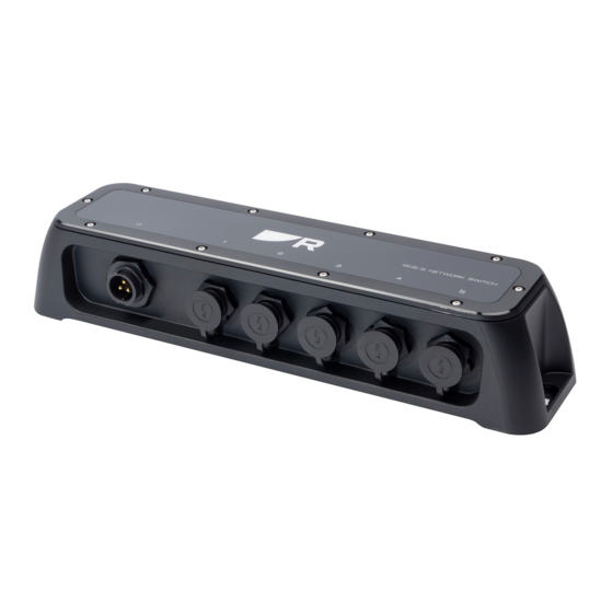
RNS-5 Network Switch (A80731) — 5-port Gigabit network switch. 2.2 Product documentation The following documentation is applicable to your product: • 87442 — RNS-5 Network Switch Installation Instructions (this document). • 87433 — RNS-5 Network Switch Mounting Template. 2.3 Document illustrations... -
Page 12: Chapter 3 Product And System Overview
CHAPTER 3: PRODUCT AND SYSTEM OVERVIEW CHAPTER CONTENTS • 3.1 Product overview — page 13 • 3.2 Required additional components — page 13 • 3.3 Typical system — page 13 • 3.4 Compatible network devices — page 14... -
Page 13: Product Overview
3.1 Product overview 3.2 Required additional components The Raymarine® RNS-5 network switch enables you to connect and share Network switches must be used in conjunction with the following items, data between multiple devices featuring a RayNet connector (or RJ45 / available separately from Raymarine®... -
Page 14: Compatible Network Devices
Example: typical system Your network switch is compatible with the following network devices: • Any Raymarine® products featuring RayNet connectors can be connected to the network switch via the use of a RayNet to RayNet network cable. • Any Raymarine® products featuring RJ45 (SeaTalkhs ®) connectors can be connected to the network switch via the use of a RayNet to RJ45 (SeaTalkhs ®) network adapter cable. -
Page 15: Chapter 4 Parts Supplied
CHAPTER 4: PARTS SUPPLIED CHAPTER CONTENTS • 4.1 Parts supplied — page 16 • 4.2 Inline fuse requirement — page 16 Parts supplied... -
Page 16: Parts Supplied
• Current rating — refer to the appropriate Power connection section of this Item Description Quantity document for further details. RNS-5 Network Switch Documentation pack Fixing screws (M4, 8.94 x 25 mm) Power cable (1.5 m (4.9 ft)) -
Page 17: Chapter 5 Product Dimensions
CHAPTER 5: PRODUCT DIMENSIONS CHAPTER CONTENTS • 5.1 Product dimensions — page 18 Product dimensions... -
Page 18: Product Dimensions
5.1 Product dimensions • A = 286.00 mm (11.26 in). • B = 72.65 mm (2.86 in). • C = 55.50 mm (2.19 in). • D = 270.70 mm (10.66 in). • E = 7.65 mm (0.30 in). • F = 34.33 mm (1.35 in). -
Page 19: Chapter 6 Location Requirements
CHAPTER 6: LOCATION REQUIREMENTS CHAPTER CONTENTS • 6.1 Warnings and cautions — page 20 • 6.2 General location requirements — page 20 • 6.3 Ignition Protection — page 20 • 6.4 EMC installation guidelines — page 20 • 6.5 Connections to other equipment — page 21 •... -
Page 20: Warnings And Cautions
For optimum EMC performance we recommend that wherever possible: • Mounting surface — Ensure product is adequately supported on a secure • Raymarine® equipment and cables connected to it are: surface. Do not mount units or cut holes in places which may damage –... -
Page 21: Connections To Other Equipment
6.5 Connections to other equipment Requirement for ferrites on non-Raymarine cables: If your Raymarine equipment is to be connected to other equipment using a cable not supplied by Raymarine, a suppression ferrite MUST always be attached to the cable near the Raymarine unit. -
Page 22: Chapter 7 Mounting
CHAPTER 7: MOUNTING CHAPTER CONTENTS • 7.1 Tools required — page 23 • 7.2 Mounting the unit — page 23... -
Page 23: Tools Required
7.1 Tools required Product installation requires the following tools: 1. Prepare the mounting surface: i. Fix the supplied mounting template to the chosen location, using masking or self-adhesive tape. Power drill ii. Drill 2 holes as indicated on the template to accept the fixings. 2. -
Page 24: Chapter 8 Cables And Connections - General Information
CHAPTER 8: CABLES AND CONNECTIONS — GENERAL INFORMATION CHAPTER CONTENTS • 8.1 General cabling guidance — page 25 • 8.2 Typical system — page 26 • 8.3 Expanded system — page 27 • 8.4 Multiple switches — page 27 • 8.5 Network cable connector types —... -
Page 25: General Cabling Guidance
– High current carrying AC and DC power lines. • Unless otherwise stated only use cables supplied by Raymarine. – Antennas. • Where it is necessary to use non-Raymarine cables, ensure that they are of correct quality and gauge for their intended purpose. (e.g.: longer power Strain relief... -
Page 26: Connecting Cables
• Use only ferrites of the correct type, supplied by Raymarine® or its Example: typical system authorized dealers. • Where an installation requires multiple ferrites to be added to a cable, additional cable clips should be used to prevent stress on the connectors due to the extra weight of the cable. -
Page 27: Expanded System
Example: daisy-chain connection scenario Thermal camera. Note: 2. RNS-5 Network Switch. If daisy-chaining 4 or more network switches together within a system, it 3. Radar scanner. is recommended that one network switch is used as a central connection 4. -
Page 28: Network Cable Connector Types
For further information on additional cabling options, refer to the following section: p.47 — Spares and accessories The RNS-5 network switch includes the following connections: 8.5 Network cable connector types Note: The network switch is supplied with protective caps fitted to the RayNet There are 3 types of network cable connectors —... -
Page 29: Chapter 9 Network Connections
CHAPTER 9: NETWORK CONNECTIONS CHAPTER CONTENTS • 9.1 Equipment connections — page 30 • 9.2 RayNet cable connections — page 30 • 9.3 RJ45 (SeaTalkhs ®) cable connections — page 30 • 9.4 RJ45 cable connections — page 31 • 9.5 Network cable extensions —... -
Page 30: Equipment Connections
Equipment is connected to the network switch using either a RayNet cable or a RayNet to RJ45, or RJ45 (SeaTalkhs ®) adapter cable. The following section provides examples of 3 different connection scenarios that may be applicable when connecting your equipment to the RNS-5 Network Switch: Connection to equipment featuring RayNet connectors: p.30 —... -
Page 31: Rj45 Cable Connections
9.4 RJ45 cable connections p.47 — Spares and accessories Connecting the RNS-5 network switch to equipment featuring an RJ45 connector. Required cabling / connectors: • RayNet (female) to RJ45 (male) adapter cable (not supplied). -
Page 32: Chapter 10 Power Connections
CHAPTER 10: POWER CONNECTIONS CHAPTER CONTENTS • 10.1 Power connection — page 33 • 10.2 Power distribution — page 33 • 10.3 Power cable extension (12 / 24 V systems) — page 35 • 10.4 Power cable drain wire connection — page 36... -
Page 33: Power Connection
Important: • When planning and wiring, take into consideration other products in RNS-5 Network Switch. your system, some of which (e.g. sonar modules) may place large power 2. 1.5 m (4.9 ft) Power cable (supplied). demand peaks on the vessel’s electrical system, which may impact the voltage available to other products during the peaks. - Page 34 Implementation — connection to distribution panel (Recommended) Item Description Waterproof fuse holder containing a suitably-rated inline fuse must be fitted. For suitable fuse rating, refer to: Inline fuse and thermal breaker ratings. Product power cable. Drain wire connection point. Item Description •...
-
Page 35: Power Cable Extension (12 / 24 V Systems)
available), or the battery’s negative terminal. For more information, refer Suitable for a vessel without a common grounding point. In this case, the p.36 — Power cable drain wire connection power cable’s drain wire should be connected directly to the battery’s negative terminal. -
Page 36: Power Cable Drain Wire Connection
• for runs of <1 m (3 ft), use 6 mm2 (10 AWG) or greater. Important: • for runs of >1 m (3 ft), use 8 mm2 (8 AWG) or greater. Be aware that some products in your system (such as sonar modules) can create voltage peaks at certain times, which may impact the voltage In any grounding system, always keep the length of connecting braid or available to other products during the peaks. -
Page 37: Chapter 11 Troubleshooting
CHAPTER 11: TROUBLESHOOTING CHAPTER CONTENTS • 11.1 Troubleshooting — page 38 • 11.2 Power up troubleshooting — page 38 • 11.3 LED diagnostics — page 38 Troubleshooting... -
Page 38: Troubleshooting
Incorrect power connection and operation of your product. The power supply may be wired incorrectly, ensure the installation Before packing and shipping, all Raymarine® products are subjected to instructions have been followed. comprehensive testing and quality assurance programs. If you do experience... - Page 39 Port speed / activity LEDs (1 / 2 / 3 / 4 / 5) LED Indication LED Status and required action (Green) 1,000 Mbits/s Ethernet Active (no transfer) • Normal operation — no user action is required. (Green) 1,000 Mbits/s Ethernet Active (transferring) •...
-
Page 40: Chapter 12 Maintenance
CHAPTER 12: MAINTENANCE CHAPTER CONTENTS • 12.1 Service and maintenance — page 41 • 12.2 Routine equipment checks — page 41 • 12.3 Product cleaning — page 41... -
Page 41: Service And Maintenance
12.1 Service and maintenance This product contains no user serviceable components. Please refer all maintenance and repair to authorized Raymarine dealers. Unauthorized repair may affect your warranty. 12.2 Routine equipment checks It is recommended that you perform the following routine checks, on a regular basis, to ensure the correct and reliable operation of your equipment: •... -
Page 42: Chapter 13 Technical Support
CHAPTER 13: TECHNICAL SUPPORT CHAPTER CONTENTS • 13.1 Raymarine product support and servicing — page 43 • 13.2 Diagnostic product information — page 44 • 13.3 Learning resources — page 44... -
Page 43: Raymarine Product Support And Servicing
Raymarine offers dedicated service departments for warranty, service, and • E-Mail: support.it@raymarine.com repairs. • Tel: +39 02 9945 1001 Don’t forget to visit the Raymarine website to register your product for Spain (Authorized Raymarine distributor): extended warranty benefits: http://www.raymarine.co.uk/display/?id=788. • E-Mail: sat@azimut.es United Kingdom (UK), EMEA, and Asia Pacific: •... -
Page 44: Diagnostic Product Information
Raymarine regularly runs a range of in-depth training courses to help you • E-Mail: support.dk@raymarine.com make the most of your products. Visit the Training section of the Raymarine • Tel: +45 437 164 64 website for more information: Russia (Authorized Raymarine distributor): •... -
Page 45: Chapter 14 Technical Specification
CHAPTER 14: TECHNICAL SPECIFICATION CHAPTER CONTENTS • 14.1 Technical specification — page 46 Technical specification... -
Page 46: Technical Specification
14.1 Technical specification Conformance specification Approvals: • EN 60945:2002 (Europe, Australia New Physical specification Zealand) Dimensions: • Length: 286 mm (11.26 in) • EN ISO 8846:2017 • Width: 72.6 mm (2.86 in) • ICES-003 (Canada) • Height: 55.5 mm (2.19 in) •... -
Page 47: Chapter 15 Spares And Accessories
CHAPTER 15: SPARES AND ACCESSORIES CHAPTER CONTENTS • 15.1 Spares — page 48 • 15.2 Accessories — page 49 Spares and accessories... -
Page 48: Spares
15.1 Spares The following spares are available for your product: • 1.5 m (4.9 ft) Power cable — A80346... -
Page 49: Accessories
15.2 Accessories RayNet to RayNet cables and connectors Standard RayNet connection cable with a RayNet (female) socket on both ends. 2. Right-angle RayNet connection cable with a straight RayNet (female) socket on one end, and a right-angle RayNet (female) socket on the other end. Suitable for connecting at 90°... -
Page 50: Raynet To Rj45, And Rj45 (Seatalkhs) Adapter Cables
RayNet to RJ45, and RJ45 (SeaTalkhs) adapter cables... - Page 51 Adapter cable with a RayNet (female) socket on one end, and a waterproof (female) RJ45 (SeaTalkhs ®) socket on the other end, accepting the following cables with an RJ45 (SeaTalkhs ®) waterproof locking (male) plug: • A62245 (1.5 m). • A62246 (15 m). 2.
- Page 53 Index Mounting template.................11 Accessories ..................... 49 Electromagnetic Compatibility............. 7, 20 Network adapter cables ..............50 EMC, See Electromagnetic Compatibility Network cables..................49 RayNet cables..................49 Applicable products ..................11 Ignition Protection ...................20 Installation Best practice ..................35 Cable Mounting....................22 Interference Bend radius..................25 Compass....................21 Protection ....................
- Page 54 Sharing a breaker ................34 Power cable extension ................35 Warranty ....................8, 43 Product overview..................13 WEEE Directive..................8 Product recycling (WEEE) ................8 Product support..................43 RayNet cables ................... 49–50 Required additional components ............. 13 RJ45 cables ....................50 Routine checks ..................
- Page 56 PO15 5RJ. United Kingdom. Tel: (+44) (0)1329 246 700 www.raymarine.co.uk Raymarine (US) 9 Townsend West, Nashua, NH 03063. United States of America. Tel: (+1) 603-324-7900 www.raymarine.com Raymarine Belgium BVBA (EU) Luxemburgstraat 2, 2321 Meer. Belgium. Tel: (+32) (0) 3665 5162 www.raymarine.com...
Need help?
Do you have a question about the RNS-5 and is the answer not in the manual?
Questions and answers