
Related Manuals for R.V.R. Elettronica PJ1000C-LCD


Summary of Contents for R.V.R. Elettronica PJ1000C-LCD
- Page 1 PJ1000C-LCD PJ1300C-LCD PJ2000LCD USER MANUAL VOLUME1 Manufactured by R.V.R ELETTRONICA S.p.A. Italy...
- Page 2 Reason Editor 28/02/2011 First Version J. H. Berti PJ1000_1300_2000C-LCD - User Manual Version 1.0 © Copyright 2011 R.V.R. Elettronica SpA Via del Fonditore 2/2c - 40138 - Bologna (Italia) Telephone: +39 051 6010506 Fax: +39 051 6011104 Email: info@rvr.it Web: www.rvr.it...
-
Page 3: Table Of Contents
Preparation First power-on and setup Operation Management Firmware 6. Identification and Access to the modules Upper View PJ1000/1300C-LCD Bottom View PJ1000/1300C-LCD Spare Parts list PJ1000C-LCD Spare Parts list PJ1300C-LCD Spare Parts list PJ2000LCD Working Principles PJ1000C/1300C/2000LCD Common Parts PJ1000/1300C-LCD Different Parts PJ2000LCD Different Parts User Manual... - Page 4 PJ1000C/13000C/2000LCD ELETTRONICA This page was intentionally left blank User Manual Rev. 1.0 - 28/02/11...
-
Page 5: Preliminary Instructions
2. Warranty La R.V.R. Elettronica warrants this product to be free from R.V.R. Elettronica shall not be liable for injury to persons or defects in workmanship and its proper operation subject to the limitations set forth in the supplied Terms and Conditions. -
Page 6: First Aid
Make sure to specify equipment model and serial number, as well as part description and 3.1.2 If the victim is conscious quantity. R.V.R. Elettronica • Cover victim with a blanket. Via del Fonditore, 2/2c • Try to reassure the victim. -
Page 7: General Description
This design facilitates maintenance and module replacement. The RF power section uses for PJ1000C-LCD four MOSFET SD2932 modules able to deliver over 300W each, for PJ1300C-LCD four MOSFET SD2942 modules modules able to deliver over 350W each, while PJ2000LCD uses four MOSFET 2xSD2932 modules able to deliver over 600 W each. - Page 8 PJ1000C/1300C/2000LCD ELETTRONICA • User-selectable threshold settings for output power alarm (Power Good feature) • Measurement and display of amplifier operating parameters. • Communication with external devices such as programming or telemetry systems via RS232 serial interface or I Four LEDs on the front panel provide the following status indications: ON, FAULT, FOLDBACK and RF MUTE.
-
Page 9: Frontal Panel Description
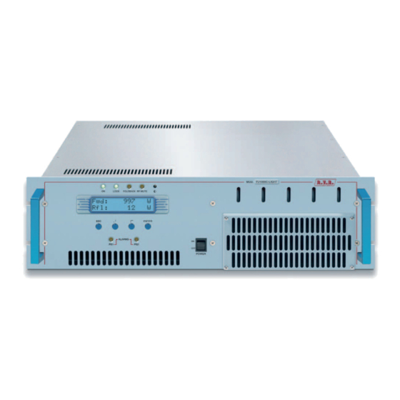
PJ1000C/1300C/2000LCD ELETTRONICA 4.3 Frontal Panel Description 4.3.1 Frontal Panel Description PJ1000/1300C-LCD [1] ON Green LED, lit on when the amplifier is working. [2] FAULT Red LED, lit on in presence of a fault that can not be resolved automatically. [3] FOLDBACK Yellow LED, lit on when the foldback current limiting (Automatic Gain Control) is intervened. - Page 10 PJ1000C/1300C/2000LCD ELETTRONICA 4.3.2 Frontal Panel Description PJ2000LCD [1] ON Green LED, lit on when the amplifier is working. [2] FAULT Red LED, lit on in presence of a fault that can not be resolved automatically. [3] FOLDBACK Yellow LED, lit on when the foldback current limiting (Automatic Gain Control) is intervened.
-
Page 11: Rear Panel Description
PJ1000C/1300C/2000LCD ELETTRONICA 4.4 Rear Panel Description 4.4.1 Rear Panel Description PJ1000/1300C-LCD [1] R.F. TEST -60dBc Output at -60 dB refered to output power level, adapted to modulation monitoring. Do not use it for spectral analysis. [2] AIR FLOW Grid for the intake of the air flow of the forced ventilation. [3] REMOTE DB25 connector for telemetry of the machine. - Page 12 PJ1000C/1300C/2000LCD ELETTRONICA 4.4.2 Rear Panel Description PJ2000LCD [1] AIR FLOW Grid for the intake of the air flow of the forced ventilation. [2] AIR FLOW Grid for the intake of the air flow of the forced ventilation. [3] INPUT PWR RF input connector, N-type.
-
Page 13: Connectors Description
PJ1000C/1300C/2000LCD ELETTRONICA 4.5 Connectors Description 4.5.1 Remote Type: Female DB25 N.C. RF power amplifier voltage 3,9V x 50V Reflected Power 3.9V x 100/100/175W (depending on model) Interlock Set 4 “On” command Set 1 WAIT Reset alarm Interlock N.C. RF power amplifier current 3.9V x 47/47/94A (depending on model) Forward Power... - Page 14 PJ1000C/1300C/2000LCD ELETTRONICA 4.5.3 Service (for programming of factory parameters) Type: Female DB9 TX_D RX_D Internally connected with 6 Internally connected with 4 Internally connected with 8 Internally connected with 7 User Manual / 36 Rev. 1.0 - 28/02/11...
-
Page 15: Technical Description
PJ1000C/1300C/2000LCD ELETTRONICA 4.6 Technical Description PJ1000C-LCD PJ1300C-LCD PJ2000LCD Parameters GENERALS Rated output power 1000W 1300W 2000W Frequency range FCC -CCIR and other on request Input power for rated output Primary Power 115 Vac ±15% or 230 Vac ±15% 230 Vac ±15%... -
Page 16: Quick Guide For Installation And Use
The following fuses are used: @ 115 VAC @ 230 VAC Main Fuse 25A type 10x38 16A type 10x38 (PJ1000C-LCD) Main Fuse 25A type 10x38 16A type 10x38 (PJ1300C-LCD) Main Fuse 16A type 10x38 (PJ2000LCD) Table 5.1: Main Fuse... - Page 17 Connect the amplifier INTERLOCK OUT output to the matching INTERLOCK IN input fitted on all R.V.R. Elettronica exciters as standard; if your exciter is a different brand, identify an equivalent input. Connect the RF output to an adequately rated dummy load or to the antenna.
-
Page 18: First Power-On And Setup
PJ1000C/1300C/2000LCD ELETTRONICA Figure 5.1: connections with amplifier WARNING: Electric shock hazard! Never handle the RF output connector when the equipment is powered on and no load is connected. Injury or death may result. Ensure that the POWER switch on the front panel is set to “OFF”. Connect the mains power cable to the MAINS terminal board on the rear panel. Note : The mains must be equipped with adequate ground connection properly connected to the machine. - Page 19 PJ1000C/1300C/2000LCD ELETTRONICA 5.2.2 Power-on Dopo aver effettuato i collegamenti descritti al paragrafo precedente, accendere l’amplificatore agendo sull’interruttore di alimentazione presente sul frontale. Accendere anche l’eccitatore di pilotaggio. 5.2.3 Power check Ensure that the ON light turns on. Machine name should appear briefly on the display, quickly followed by forward and reflected power readings (figure 5.2 - menu 1).
-
Page 20: Operation
PJ1000C/1300C/2000LCD ELETTRONICA Note : Output power can also be set in a Pwr OFF condition; in this condition, (Fwd) output power reading on the display will be 0 (zero), whereas the SET bar, which you can control using the keys, provides a graphic display of the amount of power that will be delivered the moment you switch back to Pwr ON state. - Page 21 Example ≅ 2000W in output (mod.PJ2000LCD) ≅ 1300W in output Full bar output power 100% (mod.PJ1300C-LCD) ≅ 1000W in output (mod.PJ1000C-LCD) ≅ 1000W in uscita (mod.PJ2000LCD) ≅ 650W in output Half bar output power (mod.PJ1300C-LCD) ≅ 500W in output (mod.PJ1000C-LCD) ≅...
-
Page 22: Management Firmware
PJ1000C/1300C/2000LCD ELETTRONICA In the same menu, ensure that power limiting is disabled: if PWR is set to OFF, i.e. power output is disabled, move cursor to PWR. Press ENTER and label will switch to ON, i.e. power output enabled. Press ESC twice to go back to the default menu (menu 1). 3) Fine tune power setting from menu 2 (see description of item 1b) until achieving the desired value. - Page 23 PJ1000C/1300C/2000LCD ELETTRONICA Menù 2 Menù 2 Menù 1 Menù 1 Menù Predefinito Menù Regolazione Potenza Menù 3 Menù 3 Menù di Selezion Menù 4 Menù 4 Menu Funzione Menù 5 Menù 5 Menu Potenza Menù 6 Menù 6 Menu P.A. Menù...
- Page 24 Modifies Power Good (forward power) threshold. The Power Good rate is a percent of machine rated power (1000W for PJ1000C-LCD, 1300W for PJ1300C-LCD and 2000 W for PJ2000LCD), not of forward output power. This means that this threshold set at 50% will give 150 W regardless of set power level.
- Page 25 PJ1000C/1300C/2000LCD ELETTRONICA 5.4.2 Power Menu (Pwr) This screen holds all readings related to machine output power: Menu 5 Forward power reading. Reflected power reading. Input power reading. Note that these are readings, rather than settings, and cannot be edited (note the empty arrow).
- Page 26 PJ1000C/1300C/2000LCD ELETTRONICA 5.4.4 Alarm Menu (Alm) This menu shows any alarm conditions occurring during machine operation. Alarm thresholds are preset at the factory. Menu 7 Conteggio delle situazioni di allarme dovuti a potenza diretta. Conteggio delle situazioni di allarme dovuti a potenza riflessa. Conteggio delle situazioni di allarme dovuti a potenza in ingresso.
- Page 27 PJ1000C/1300C/2000LCD ELETTRONICA 1. Over Forward Power Forward power threshold exceeded. Alarm 1 2. Over Reflected Power Reflected power threshold exceeded. Alarm 2 3. Over Input Power Input power threshold exceeded. Alarm 3 Monitoring cycle is as follows: • An alarm condition occurs; • Alarm is displayed and device is locked out for 15 sec.; •...
- Page 28 PJ1000C/1300C/2000LCD ELETTRONICA II. Over Reflected Power Reflected power alarm display. Stop 2 III. Over Input Power Input power alarm display. Stop 3 Once the machine goes into “FAULT” mode, it will no longer attempt to re-start; choose the appropriate reset procedure according to current machine setting: •...
- Page 29 PJ1000C/1300C/2000LCD ELETTRONICA 5.4.5 Miscellaneous Menu (Mix) This menu lets you set machine address in an I C bus serial connection: Menu 8 C address setting. The I C network address becomes significant when the exciter is connected in an RVR transmission system that uses this protocol.
-
Page 30: Identification And Access To The Modules
PJ1000C/1300C/2000LCD ELETTRONICA 6. Identification and Access to the Modules The PJ1000C-LCD, PJ1300C-LCD and PJ2000LCD is made up of various modules linked to each other through connectors so as to make maintenance and any required module replacement easier. 6.1 Upper View PJ1000/1300C-LCD The figure below shows the upper view of the machine (230V version, only one PFC module) with the various components pointed out. -
Page 31: Bottom View Pj1000/1300C-Lcd
PJ1000C/1300C/2000LCD ELETTRONICA 6.2 Bottom View PJ1000/1300C-LCD The figure below shows the bottom view of the machine with the various components pointed out. figure 6.2 [1] LED PS Board [2] Inteface Board [3] Power Supply 24V 3A [4] Telemetry Board User Manual Rev. 1.0 - 28/02/11 / 36... -
Page 32: Spare Parts List Pj1000C-Lcd
PJ1000C/1300C/2000LCD ELETTRONICA 6.3 Spare Parts list PJ1000C-LCD RF final block SL010RF1002 CPU Panel + Display KPANPJCLB06 Secondary cooling fan VTL4184 Main cooling fan VTL4114NH3 Switching power supply KPSL1000/PJ1K PFC block KPFCPSL1000 Interface board SL010IN5003 Service power supply block KPSL2403-03 Surge protection block... -
Page 33: Working Principles
PJ1000C/1300C/2000LCD ELETTRONICA 7. Working Principles Figure 7.1 below provides an overview of PJ1000C-LCD, PJ1300C-LCD and PJ2000LCD modules and connections. R.F. R.F. 4 X R.F. 4 X R.F. R.F. OUTPUT LPF + DRIVER SPLITTER RF MODULES COMBINER DIRECT. COUPL. VPA (50VDC) BIAS 4 X VPA (50VDC) R.F. INPUT (AUDIO/RDS) MAIN BOARD FUSE BOARD FWD PWR... - Page 34 PJ1000C/1300C/2000LCD ELETTRONICA • It processes and provides interfacing of the control signals to/from the Panel Board; • It feeds and operates the cooling fans; • It feeds and controls the LED indicator board. 7.1.3 Telemetry board This board provides an I/O interface for the CPU with the outside environment. All available machine input and output signals are brought to the REMOTE DB25 connector.
-
Page 35: Pj1000/1300C-Lcd Different Parts
PJ1000C/1300C/2000LCD ELETTRONICA 7.2 PJ1000/1300C-LCD Different Parts 7.2.1 Power Supply The PJ1000C/1300C-LCD power supply section is made up of a surge protection module and two power supply units: 1. Over range protection. Surge Protection board protects machine from eventual unexpected variations of the mains voltage. 2. - Page 36 Every RF module supplies 350 watts in PJ1300C-LCD model, or 300 watts in PJ1000C-LCD model, and is supplied from own switching supply. The active device used in the amplifier modules is a Mosfet (SD2942 in PJ1300C- LCD model, or SD2032 in PJ1000C-LCD model).
-
Page 37: Pj2000Lcd Different Parts
PJ1000C/1300C/2000LCD ELETTRONICA Without alarm condition, Bias voltage is regulated only in function of output power set up, with a feedback mechanism based on the reading of the effectively distributed power (AGC). Bias voltage is also influenced from other factors like: - Excess of reflected voltage - External AGC signals (Ext. - Page 38 PJ1000C/1300C/2000LCD ELETTRONICA • Power output disabled (set to OFF) by user in FNC operation menu; • Regulated power set to 0 Watt using the edit mode; • An alarm or fault condition has occurred. 7.3.3 Power Amplifier The RF power amplification section consists in four power modules coupled through a Wilkinson splitter and combiner using strip-line technology.
- Page 39 PJ1000C/1300C/2000LCD ELETTRONICA Under normal conditions, bias voltage is adjusted according to set output power using feedback based on actual output power reading (AGC). Abnormal conditions affecting bias voltage so as to trigger foldback current limiting are: • Reflected output power too high •...
- Page 40 PJ1000C/1300C/2000LCD ELETTRONICA This page was intentionally left blank User Manual / 36 Rev. 1.0 - 28/02/11...
- Page 41 ______________________________________________________________________________ ______________________________________________________________________________ ______________________________________________________________________________ ______________________________________________________________________________ ______________________________________________________________________________ ______________________________________________________________________________ ______________________________________________________________________________ ______________________________________________________________________________ ______________________________________________________________________________ ______________________________________________________________________________ ______________________________________________________________________________ ______________________________________________________________________________ ______________________________________________________________________________ ______________________________________________________________________________ ______________________________________________________________________________ ______________________________________________________________________________ ______________________________________________________________________________ ______________________________________________________________________________ ______________________________________________________________________________ ______________________________________________________________________________ ______________________________________________________________________________ ______________________________________________________________________________ ______________________________________________________________________________ ______________________________________________________________________________ ______________________________________________________________________________...
- Page 42 ______________________________________________________________________________ ______________________________________________________________________________ ______________________________________________________________________________ ______________________________________________________________________________ ______________________________________________________________________________ ______________________________________________________________________________ ______________________________________________________________________________ ______________________________________________________________________________ ______________________________________________________________________________ ______________________________________________________________________________ ______________________________________________________________________________ ______________________________________________________________________________ ______________________________________________________________________________ ______________________________________________________________________________ ______________________________________________________________________________ ______________________________________________________________________________ ______________________________________________________________________________ ______________________________________________________________________________ ______________________________________________________________________________ ______________________________________________________________________________ ______________________________________________________________________________ ______________________________________________________________________________ ______________________________________________________________________________ ______________________________________________________________________________ ______________________________________________________________________________...
- Page 43 ______________________________________________________________________________ ______________________________________________________________________________ ______________________________________________________________________________ ______________________________________________________________________________ ______________________________________________________________________________ ______________________________________________________________________________ ______________________________________________________________________________ ______________________________________________________________________________ ______________________________________________________________________________ ______________________________________________________________________________ ______________________________________________________________________________ ______________________________________________________________________________ ______________________________________________________________________________ ______________________________________________________________________________ ______________________________________________________________________________ ______________________________________________________________________________ ______________________________________________________________________________ ______________________________________________________________________________ ______________________________________________________________________________ ______________________________________________________________________________ ______________________________________________________________________________ ______________________________________________________________________________ ______________________________________________________________________________ ______________________________________________________________________________ ______________________________________________________________________________...
- Page 44 ISO 9001:2000 certified since 2000 R.V.R Elettronica S.p.A. Via del Fonditore, 2 / 2c Zona Industriale Roveri · 40138 Bologna · Italy Phone: +39 051 6010506 · Fax: +39 051 6011104 e-mail: info@rvr.it ·web: http://www.rvr.it The RVR Logo, and others referenced RVR products and services are trademarks of RVR Elettronica S.p.A. in Italy, other countries or both. RVR ® 1998 all rights reserved. All other trademarks, trade names or logos used are property of their respective owners.
Need help?
Do you have a question about the PJ1000C-LCD and is the answer not in the manual?
Questions and answers