Table of Contents
Advertisement
Quick Links
Compact Inverter
Three-phase 200 V series: FRN0001 to 0020C2S-2
Three-phase 400 V series: FRN0002 to 0011C2S-4
Single-phase 200 V series: FRN0001 to 0012C2S-7
Thank you for purchasing our FRENIC-Mini series of inverters.
• This product is designed to drive a three-phase induction motor and three-phase permanent
magnet synchronous motor. Read through this instruction manual and be familiar with the
handling procedure for correct use.
• Improper handling might result in incorrect operation, a short life, or even a failure of this
product as well as the motor.
• Deliver this manual to the end user of this product. Keep this manual in a safe place until this
product is discarded.
• For instructions on how to use an optional device, refer to the instruction and installation
manuals for that optional device.
Fuji Electric Co., Ltd.
Instruction Manual
INR-SI47-1729a-E
Advertisement
Table of Contents

Related Manuals for FE FRENIC-Mini

Summary of Contents for FE FRENIC-Mini
- Page 1 Three-phase 400 V series: FRN0002 to 0011C2S-4 Single-phase 200 V series: FRN0001 to 0012C2S-7 Thank you for purchasing our FRENIC-Mini series of inverters. • This product is designed to drive a three-phase induction motor and three-phase permanent magnet synchronous motor. Read through this instruction manual and be familiar with the handling procedure for correct use.
- Page 2 Copyright © 2013 Fuji Electric Co., Ltd. All rights reserved. No part of this publication may be reproduced or copied without prior written permission from Fuji Electric Co., Ltd. All products and company names mentioned in this manual are trademarks or registered trademarks of their respective holders.
-
Page 3: Table Of Contents
Table of Contents Preface ............. iii Chapter 4 RUNNING THE MOTOR ....4-1 Safety precautions..........iv 4.1 Test Run.............4-1 Conformity to the Low Voltage Directive in the EU... ix 4.1.1 Checking prior to powering on...4-1 Precautions for use..........xi 4.1.2 Powering ON and checking ....4-1 How this manual is organized ........ - Page 4 ......11-6 11.4 Compliance with the Low Voltage Directive in the EU........11-6 11.4.1 General ..........11-6 11.4.2 Points for consideration when using the FRENIC-Mini series in a system to be certified by the Low Voltage Directive in the EU ......11-6...
-
Page 5: Preface
Have this manual delivered to the end user of this product. Keep this manual in a safe place until this product is discarded. Listed below are the other materials related to the use of the FRENIC-Mini. Read them in conjunction with this manual as necessary. -
Page 6: Safety Precautions
Fire or an accident could occur. • FRENIC-Mini may not be used for a life-support system or other purposes directly related to the human safety. • Though FRENIC-Mini is manufactured under strict quality control, install safety devices for applications where serious accidents or material losses are foreseen in relation to the failure of it. - Page 7 • Do not support the inverter by its terminal block cover during transportation. Doing so could cause a drop of the inverter and injuries. • Prevent lint, paper fibers, sawdust, dust, metallic chips, or other foreign materials from getting into the inverter or from accumulating on the heat sink. Otherwise, a fire or an accident might result.
- Page 8 • Generally, control signal wires are not reinforced insulation. If they accidentally touch any of live parts in the main circuit, their insulation coat may break for any reasons. In such a case, an extremely high voltage may be applied to the signal lines. Make a complete remedy to protect the signal line from contacting any hot high voltage lines.
- Page 9 (Design the machinery or equipment so that human safety is ensured after restarting.) • If you set the function codes wrongly or without completely understanding this instruction manual and the FRENIC-Mini User's Manual, the motor may rotate with a torque or at a speed not permitted for the machine.
- Page 10 Disposal • Handle the inverter as an industrial waste when disposing of it. Otherwise injuries could occur. Others • Never attempt to modify the inverter. Doing so could cause electric shock or injuries. GENERAL PRECAUTIONS Drawings in this manual may be illustrated without covers or safety shields for explanation of detail parts.
-
Page 11: Conformity To The Low Voltage Directive In The Eu
Conformity to the Low Voltage Directive in the EU If installed according to the guidelines given below, inverters marked with CE are considered as compliant with the Low Voltage Directive 2006/95/EC. 1. The ground terminal G should always be connected to the ground. Do not use only a residual-current-operated protective device (RCD)/earth leakage circuit breaker (ELCB)* as the sole method of electric shock protection. - Page 12 Conformity to the Low Voltage Directive in the EU (Continued) 12. Use wires listed in IEC60364-5-52. Recommended wire size (mm Main circuit Appli- Rated current (A) Control power input [P1, cable circuit Inverter [L1/R, L2/S, L3/T] motor Inverter type P (+)] MCCB or RCD/ELCB (30A, output...
-
Page 13: Precautions For Use
Precautions for use When driving a 400 V general-purpose motor with an inverter using extremely long wires, damage to the insulation of the Driving a 400 V motor may occur. Use an output circuit filter (OFL) if neces- general-purpose sary after checking with the motor manufacturer. Fuji motors motor do not require the use of output circuit filters because of their good insulation. - Page 14 If the power transmission mechanism uses an oil-lubricated gearbox or speed changer/reducer, then continuous motor Geared motors operation at low speed may cause poor lubrication. Avoid such operation. It is necessary to take special measures suitable for this Synchronous mo- In running motor type.
- Page 15 Do not mount power-factor correcting capacitors in the in- Discontinuance verter’s primary circuit. (Use the DC reactor to improve the of power-factor inverter power factor.) Do not use power-factor correcting correcting ca- capacitors in the inverter output circuit. An overcurrent trip pacitor will occur, disabling motor operation.
-
Page 16: How This Manual Is Organized
FRENIC-Mini series of inverters. Chapter 10 APPLICATION OF DC REACTOR (DCRs) This chapter describes a DC reactor that suppresses input harmonic component current. Chapter 11 COMPLIANCE WITH STANDARDS This chapter describes standards with which the FRENIC-Mini series of inverters comply. - Page 17 Icons The following icons are used throughout this manual. This icon indicates information which, if not heeded, can result in the inverter not operating to full efficiency, as well as information concerning incorrect operations and settings which can result in accidents. This icon indicates information that can prove handy when performing certain settings or operations.
-
Page 18: Chapter 1 Before Using The Inverter
Chapter 1 BEFORE USING THE INVERTER 1.1 Acceptance Inspection Unpack the package and check that: (1) An inverter and instruction manual (this manual) are contained in the package. (2) The inverter has not been damaged during transportation—there should be no dents or parts missing. -
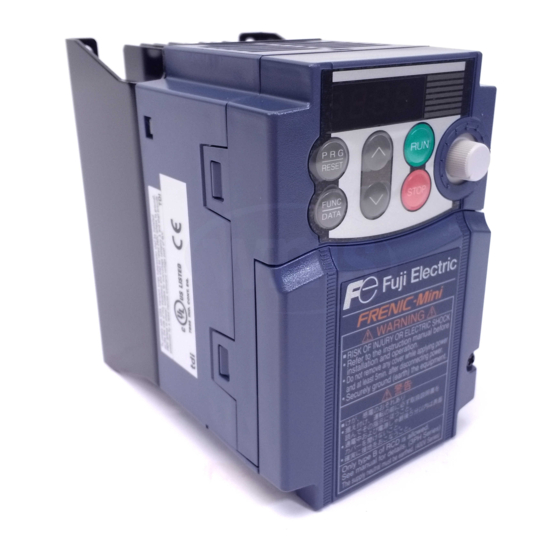
Page 19: External Views
Main circuit terminal block cover Main nameplate Main nameplate Control circuit terminal bock cover Figure 1.2 External Views of FRENIC-Mini (2) Wiring section Barrier for the RS-485 communications port* Control signal cable port DB, P1, P (+) and N (-) wire port... -
Page 20: Storage Environment
1.4 Storage Environment 1.4.1 Temporary storage Store the inverter in an environment that satisfies the requirements listed in Table 1.1. Table 1.1 Environmental Requirements for Storage and Transportation Item Requirements Storage -25 to +70°C Locations where the inverter is not temperature subject to abrupt changes in temperature that would result in the... -
Page 21: Mounting And Wiring Of The Inverter
Chapter 2 MOUNTING AND WIRING OF THE INVERTER 2.1 Operating Environment Install the inverter in an environment that satisfies the requirements listed in Table 2.1. Table 2.2 Output Current Derating Factor in Table 2.1 Environmental Requirements Relation to Altitude Item Specifications Output current Altitude... -
Page 22: Wiring
(3) Mounting direction Secure the inverter to the mounting base with four screws or bolts (M4) so that the FRENIC-Mini logo faces outwards. Tighten those screws or bolts perpendicular to the mounting base. Do not mount the inverter upside down or horizontally. Doing so will reduce the heat dissipation efficiency of the inverter and cause the overheat protection function to operate, so the inverter will not run. -
Page 23: Terminal Arrangement And Screw Specifications
2.3.2 Terminal arrangement and screw specifications The figures below show the arrangement of the main and control circuit terminals which differs according to inverter type. The two terminals prepared for grounding, which are indicated by the symbol G in Figures A to D, make no distinction between the power supply side (primary circuit) and the motor side (secondary circuit). -
Page 24: Recommended Wire Sizes
(2) Arrangement of the control circuit terminals (common to all FRENIC-Mini models) Screw size: M 2 Tightening torque: 0.2 N•m Screw size: M 2.5 Tightening torque: 0.4 N•m Table 2.4 Control Circuit Terminals Ferrule terminal* Bared wire Opening dimension in... - Page 25 Table 2.6 Recommended Wire Sizes Recommended wire size (mm Main circuit Nomi- Main circuit power input applied Inverter type [L1/R, L2/S, L3/T] Braking Control Inverter motor [L1/L, L2/N] resistor circuit output (kW) Grounding [ [P1, P (+)] [P (+), DB] [U, V, W] w/ DCR w/o DCR...
-
Page 26: Wiring Precautions
2.3.4 Wiring precautions Follow the rules below when performing wiring for the inverter. (1) Make sure that the source voltage is within the rated voltage range specified on the nameplate. (2) Be sure to connect the power wires to the main circuit power input terminals L1/R, L2/S and L3/T (for three-phase voltage input) or L1/L and L2/N (for single-phase voltage input) of the inverter. -
Page 27: Wiring For Main Circuit Terminals And Grounding Terminals
2.3.5 Wiring for main circuit terminals and grounding terminals Follow the procedure below. Figure 2.3 illustrates the wiring procedure with peripheral equipment. Wiring procedure Grounding terminal Inverter output terminals (U, V, and W) and grounding terminal DC reactor connection terminals (P1 and P(+))* Braking resistor connection terminals (P(+) and DB)* DC link bus terminals (P(+) and N(-))* Main circuit power input terminals (L1/R, L2/S and L3/T) or (L1/L and L2/N) - Page 28 The wiring procedure for the FRN0006C2S-2 is given below as an example. For other inverter types, perform wiring in accordance with their individual terminal arrangement. (Refer to page 2-3.) Grounding terminal ( G) Be sure to ground either of the two grounding terminals for safety and noise reduction. It is stipulated by the Electric Facility Technical Standard that all metal frames of electrical equipment must be grounded to avoid electric shock, fire and other disasters.
- Page 29 Driving 400 V series motor • If a thermal relay is installed in the path between the inverter and the motor to protect the motor from overheating, the thermal relay may malfunction even with a wiring length shorter than 50 m. In this situation, add an output circuit filter (option) or lower the carrier frequency (Function code F26: Motor sound (Carrier frequency)).
- Page 30 Braking resistor terminals, P(+) and DB 1) Connect terminals P and DB of a braking resistor (option) to terminals P(+) and DB on the main circuit terminal block. 2) Arrange the inverter and braking resistor to keep the wiring length to 5 m or less and twist the two wires or route them together in parallel.
-
Page 31: Wiring For Control Circuit Terminals
Main circuit power input terminals, L1/R, L2/S, and L3/T (for three-phase voltage input) or L1/L and L2/N (for single-phase voltage input) 1) For safety, make sure that the molded case circuit breaker (MCCB) or magnetic contactor (MC) is turned off before wiring the main circuit power input terminals. 2) Connect the main circuit power supply wires (L1/R, L2/S and L3/T or L1/L and L2/N) to the input terminals of the inverter via an MCCB or residual-current-operated protective device (RCD)/earth leakage circuit breaker (ELCB)*, and MC if necessary. - Page 32 Table 2.8 Symbols, Names and Functions of the Control Circuit Terminals Symbol Name Functions [13] Power Power supply (+10 VDC) for an external frequency command potentiometer supply for (Potentiometer: 1 to 5 kΩ) potenti- A potentiometer of 1/2 W rating or more should be connected. ometer [12] Analog...
- Page 33 Table 2.8 Symbols, Names and Functions of the Control Circuit Terminals (Continued) Symbol Name Functions - These low level analog signals are especially susceptible to the external noise effects. Route the wiring as short as possible (within 20 m) and use shielded wires. In principle, ground the shielded sheath of wires;...
- Page 34 Table 2.8 Symbols, Names and Functions of the Control Circuit Terminals (Continued) Symbol Name Functions [X1] Digital (1) The various signals such as "Coast to a stop," "Enable external alarm input 1 trip," and "Select multistep frequency" can be assigned to terminals [X1] to [X3], [FWD] and [REV] by setting function codes E01 to E03, E98, and [X2] Digital...
- Page 35 Table 2.8 Symbols, Names and Functions of the Control Circuit Terminals (Continued) Symbol Name Functions Using a relay contact to turn [X1], [X2], [X3], [FWD] or [REV] ON or OFF Figure 2.7 shows two examples of a circuit that uses a relay contact to turn control signal input [X1], [X2], [X3], [FWD] or [REV] ON or OFF.
- Page 36 Table 2.8 Symbols, Names and Functions of the Control Circuit Terminals (Continued) Symbol Name Functions The monitor signal for analog DC voltage (0 to +10 VDC) is output. The [FMA] Analog signal functions can be selected from the following with function code F31. monitor - Output frequency (before slip compensation) - Output frequency (after slip compensation)
- Page 37 Table 2.8 Symbols, Names and Functions of the Control Circuit Terminals (Continued) Symbol Name Functions Connecting programmable controller (PLC) to terminal [Y1] Figure 2.9 shows two examples of circuit connection between the transistor output of the inverter’s control circuit and a PLC. In example (a), the input circuit of the PLC serves as a sink for the control circuit, whereas in example (b), it serves as a source for the control circuit.
-
Page 38: Setting Up The Jumper Switches
(such as the terminal block of the main circuit). - The pin assignment of the RJ-45 connector on the FRENIC-Mini series is different from that of the RJ-45 connector on the FVR-E11S series keypad. Do not connect them with each other;... - Page 39 Figure 2.11 shows the locations of jumper switches and the RJ-45 connector. SOURCE SINK (Factory default for (Factory default for FRN_ _ _ _C2S-_E) FRN_ _ _ _C2S-_A, C, U) (Factory default for all inverter types) RJ-45 connector Figure 2.11 Locations of Jumper Switches and RJ-45 Connector 2-19...
-
Page 40: Cautions Relating To Harmonic Component, Noise, And Leakage Current
2.3.8 Cautions relating to harmonic component, noise, and leakage current (1) Harmonic component Input current to an inverter includes a harmonic component that may affect other motors and phase-advancing capacitors on the same power supply line. If the harmonic component causes any problems, connect a DC reactor (option) to the inverter. -
Page 41: Operation Using The Keypad
In Programming mode: Pressing this key displays the function codes and sets their data entered with the keys or the POT. In Alarm mode: Pressing this key displays detailed alarm information. * FRENIC-Mini features three operation modes: Running, Programming, and Alarm. Refer to Section 3.2 "Overview of Operation Modes."... -
Page 42: Overview Of Operation Modes
Simultaneous keying Simultaneous keying means pressing two keys at the same time (expressed by "+"). FRENIC-Mini supports simultaneous keying as listed below. (For example, the expression " keys" stands for pressing the key while holding down the key.) Table 3.2 Simultaneous Keying... - Page 43 Figure 3.2 illustrates the transition of the LED monitor screen during the Running mode, the transi- tion between menu items in the Programming mode, and the transition between alarm codes at different occurrences in the Alarm mode. *1 In speed monitor, you can display any of the following according to the setting of function code E48: Output frequency (Hz), Reference frequency (Hz), Load shaft speed (r/min), Line speed (m/min), and Constant rate of feeding time (min).
-
Page 44: Monitoring The Running Status
3.3 Running mode When the inverter is turned on, it automatically enters Running mode. In Running mode, you can: (1) Monitor the running status (e.g., output frequency, output current), (2) Set up the reference frequency and PID process command, and (3) Run/stop the motor. -
Page 45: Setting Up Reference Frequency And Pid Process Command
Setting up the PID process command To enable PID control, you need to set function code J01 to "1" or "2." Refer to the FRENIC-Mini User's Manual for details on the PID control. - Page 46 Setting the PID process command with the built-in potentiometer (1) Set function code E60 to "3: PID process command 1." (2) Set function code J02 to "1: PID process command 1." Setting the PID process command with the keys (1) Set function code J02 to "0: keys on the built-in keypad."...
-
Page 47: Running/Stopping The Motor
3.3.3 Running/stopping the motor By factory default, pressing the key starts running the motor in the forward direction and pressing the key decelerates the motor to stop. key is enabled only in Running mode. By changing the setting of function code F02, you can change the starting direction of motor rotation;... -
Page 48: Programming Mode
3.4 Programming mode Programming mode provides you with these functions--setting and checking function code data, monitoring maintenance information and checking input/output (I/O) signal status. The functions can be easily selected with the menu-driven system. Table 3.5 lists menus available in Programming mode. - Page 49 Figure 3.3 illustrates the menu transition in Programming mode. * Displayed only when a remote keypad (option) is set up for use. Figure 3.3 Menu Transition in Programming Mode Limiting menus to be displayed The menu-driven system has a limiter function (specified by function code E52) that limits menus to be displayed for the purpose of simple operation.
-
Page 50: Setting Up The Function Codes - "Data Setting
To set function codes in Menu #1 "Data setting," it is necessary to set function code E52 data to "0" (Function code data editing mode) or "2" (Full-menu mode). The table below lists the function codes available in the FRENIC-Mini. The function codes are displayed on the LED monitor on the keypad as shown below. - Page 51 Figure 3.4 shows the status transition for Menu #1 "Data setting." Figure 3.4 "Data Setting" Status Transition 3-11...
- Page 52 Basic key operation This section gives a description of the basic key operation, following the example of the function code data changing procedure shown in Figure 3.5. This example shows you how to change function code F01 data from the factory default "Built-in potentiometer (POT) (F01 = 4)"...
-
Page 53: Checking Changed Function Codes - "Data Checking
Figure 3.5 Example of Function Code Data Changing Procedure 3.4.2 Checking changed function codes – "Data Checking" Menu #2 "Data checking" in Programming mode allows you to check function codes that have been changed. Only the function codes whose data has been changed from the factory defaults are displayed on the LED monitor. - Page 54 e 52 f 01 * Pressing the key with the data displayed returns to Figure 3.6 "Data Checking" Status Transition (When changes are made only to F01, F05, E52) Basic key operation The basic key operation is the same as for "Data setting." To check function codes in Menu #2 "Data checking,"...
-
Page 55: Monitoring The Running Status - "Drive Monitoring
3.4.3 Monitoring the running status – "Drive Monitoring" Menu #3 "Drive monitoring" is used to check the running status during maintenance and test running. The display items for "Drive monitoring" are listed in Table 3.8. Figure 3.7 shows the status transition diagram for "Drive monitoring."... - Page 56 Basic key operation Before checking the running status on the drive monitor, set function code E52 to "2" (Full-menu mode). (1) When the inverter is powered on, it automatically enters Running mode. In that mode, press the key to switch to Programming mode. The function selection menu appears. #ope (2) With the menu displayed, use the keys to select "Drive monitoring"...
- Page 57 Displaying running status To display the running status in hexadecimal format, each state has been assigned to bits 0 to 15 as listed in Table 3.9. Table 3.10 shows the relationship between each of the status assignments and the LED monitor display. Table 3.11 gives the conversion table from 4-bit binary to hexadecimal. Table 3.9 Running Status Bit Allocation Notation Content...
- Page 58 Hexadecimal expression A 4-bit binary number can be expressed in hexadecimal format (1 hexadecimal digit). Table 3.11 shows the correspondence between the two notations. The hexadecimals are shown as they appear on the LED monitor. Table 3.11 Binary and Hexadecimal Conversion Binary Binary Hexadecimal...
-
Page 59: Checking I/O Signal Status - "I/O Checking
3.4.4 Checking I/O signal status – "I/O Checking" With Menu #4 "I/O checking," you can display the I/O status of external signals without using a measuring instrument. External signals that can be displayed include digital I/O signals and analog I/O signals. Table 3.12 lists check items available. The status transition for I/O checking is shown in Figure 3.8. - Page 60 Basic key operation Before checking the status of the I/O signals, set function code E52 to "2" (Full-menu mode). (1) When the inverter is powered on, it automatically enters Running mode. In that mode, press the key to switch to Programming mode. The function selection menu appears. $i_o (2) With the menu displayed, use the keys to select "I/O check"...
- Page 61 " " each). With the FRENIC-Mini, digital input terminals [FWD] and [REV] are assigned to bit 0 and bit 1, respectively. Terminals [X1] through [X3] are assigned to bits 2 through 4. The bit is set to "1" when the corresponding input terminal is short-circuited with terminal [CM] or terminal [PLC] *, and is set to "0"...
- Page 62 Table 3.14 Segment Display for I/O Signal Status in Hexadecimal Format LED No. LED4 LED3 LED2 LED1 Input (RST)* (XR)* (XF)* X1 REV FWD terminal Output 30AC terminal Binary Hexa- decimal (See Table 3.11.) Hexa- decimal on the monitor – : No corresponding control terminal exists. * (XF), (XR), and (RST) are assigned for communication.
-
Page 63: Reading Maintenance Information - "Maintenance Information
3.4.5 Reading maintenance information – "Maintenance Information" Menu #5 "Maintenance information" in Programming mode contains information necessary for performing maintenance on the inverter. Table 3.15 lists the maintenance information display items and Figure 3.9 shows the status transition for maintenance information. Figure 3.9 "Maintenance Information"... - Page 64 Table 3.15 Maintenance Display Items LED Monitor Contents Description shows: Shows the cumulative power-ON time of the inverter. Unit: 1,000 hours. When the total ON-time is less than 10,000 hours (display: 0.001 to Cumulative run 5_00 9.999), data is shown in units of one hour. time When the total time is 10,000 hours or more (display: 10.00 to 65.53), it is shown in units of 10 hours.
- Page 65 Table 3.15 Maintenance Display Items (Continued) LED Monitor Contents Description shows: Shows the value expressed by "input watt-hour (kWh) × E51 (whose data range is 0.000 to 9,999)." Unit: None. (Display range: 0.001 to 9999. The count cannot exceed 9999. It will Input watt-hour be fixed at 9,999 once the calculated value exceeds 9999.) 5_10...
-
Page 66: Reading Alarm Information - "Alarm Information
3.4.6 Reading alarm information – "Alarm Information" Menu #6 "Alarm information" in Programming mode shows the causes of the past 4 alarms as an alarm code. Further, it is also possible to display alarm information that indicates the status of the inverter when the alarm condition occurred. - Page 67 Basic key operation Before viewing alarm information, set function code E52 to "2" (Full-menu mode). (1) When the inverter is powered on, it automatically enters Running mode. In that mode, press the key to switch to Programming mode. The function selection menu appears. &al (2) With the menu displayed, use the keys to select "Alarm information"...
- Page 68 Table 3.16 Alarm Information Displayed (Continued) LED monitor shows: Contents Description (item No.) Shows the temperature of the heat sink. Max. temperature of 6_11 heat sink Unit: ºC Terminal I/O signal status (displayed with 6_12 the ON/OFF of LED segments) Shows the ON/OFF status of the digital I/O terminals.
- Page 69 6_22 Table 3.17 Running Status 2 ( ) Bit Assignment Content Content Drive motor type 0: Induction motor, 1: Permanent magnet synchronous (Not used.) motor (PMSM) Motor selection 00: Motor 1 01: Motor 2 (Not used.) Inverter drive control 0000: V/f control with slip compensa- tion inactive 0001: Dynamic torque vector control 0010: V/f control with slip compensa-...
-
Page 70: Alarm Mode
3.5 Alarm mode When an abnormal condition occurs, the protective function is invoked to issue an alarm, and the inverter automatically switches to Alarm mode and displays the corresponding alarm code on the LED monitor. Releasing the Alarm and Transferring the Inverter to Running Mode Remove the cause of the alarm and press the key to release the alarm and return to Running mode. - Page 71 Figure 3.11 summarizes the possible transitions between different menu items. Figure 3.11 Alarm Mode Status Transition 3-31...
-
Page 72: Chapter 4 Running The Motor
Chapter 4 RUNNING THE MOTOR 4.1 Test Run 4.1.1 Checking prior to powering on Check the following prior to powering on the inverter. (1) Check the wiring to the power input terminals (L1/R, L2/S and L3/T or L1/L and L2/N) and inverter output terminals (U, V and W). -
Page 73: Preparation Before A Test Run--Configuring Function Code Data
4.1.3 Preparation before a test run--Configuring function code data Before running the motor, configure function code data specified in Table 4.1 in accordance with the motor ratings and your system design values. The motor ratings are printed on the nameplate of the motor. - Page 74 < Tuning procedure > 1) Preparation Check the rating plate on the motor and set the following function codes to their nominal ratings: • F04 and A02: Base frequency • F05 and A03: Rated voltage at base frequency • P02 and A16: Motor rated capacity •...
- Page 75 function code F02. The display of stays lit, and tuning starts with the motor stopped. (Maximum tuning time: Approx. 40 s.) If P04 or A18 = 2, the motor is accelerated to approximately 50% of the base frequency and then tuning starts. Upon completion of measurements, the motor decelerates to a stop.
-
Page 76: Test Run
4.1.4 Test run If the user configures the function codes wrongly without completely understanding this Instruction Manual and the FRENIC-Mini User's Manual, the motor may rotate with a torque or at a speed not permitted for the machine. Accident or injury may result. -
Page 77: Jogging Operation
4.2.1 Jogging Operation This section provides the procedure for jogging the motor. Making the inverter ready to jog with the steps below (The LED monitor should display • Switch the inverter to Running mode (see page 3-3). • Press the " keys"... -
Page 78: Chapter 5 Function Codes
Chapter 5 FUNCTION CODES 5.1 Function Code Tables Function codes enable the FRENIC-Mini series of inverters to be set up to match your system requirements. Each function code consists of a 3-letter alphanumeric string. The first letter is an alphabet that identifies its group and the following two letters are numerals that identify each individual code in the group. - Page 79 4th digit of the set data will not be displayed; however they will be processed correctly. The following tables list the function codes available for the FRENIC-Mini series of inverters. F codes: Fundamental Functions...
- Page 80 Change Refer Incre- Data Default Code Name Data setting range Unit when ment copying setting running page: Operation Method 0: RUN/STOP keys on keypad (Motor – – 5-22 rotational direction specified by terminal command FWD/REV) 1: Terminal command FWD or REV 2: RUN/STOP keys on keypad (forward) 3: RUN/STOP keys on keypad (reverse) Maximum Frequency 1...
- Page 81 (F codes continued) Change Refer Incre- Data Default Code Name Data setting range Unit when ment copying setting running page: Bias -100.00 to 100.00 *2 0.01 0.00 5-36 (Frequency command 1) DC Braking 1 0.0 to 60.0 5-37 (Braking starting frequency) (Braking level) 0 to 100...
- Page 82 (F codes continued) Change Refer Incre- Data Default Code Name Data setting range Unit when ment copying setting running page: Current Limiter Disable (No current limiter works.) – – 5-42 (Mode selection) Enable at constant speed (Disable during ACC/DEC) Enable during ACC/constant speed operation (Level) 20 to 180 (The data is interpreted as the...
- Page 83 E codes: Extension Terminal Functions Change Refer Incre- Data Default Code Name Data setting range Unit when ment copying setting running page: Terminal [X1] Function Selecting function code data assigns the – – 5-44 corresponding function to terminals [X1] to [X3] as listed below.
- Page 84 (E codes continued) Change Refer Incre- Data Default Code Name Data setting range Unit when ment copying setting running page: Terminal [Y1] Function Selecting function code data assigns the – – 5-52 corresponding function to terminals [Y1] and Terminal [30A/B/C] –...
- Page 85 (E codes continued) Change Refer Incre- Data Default Code Name Data setting range Unit when ment copying setting running page: Current Detection 2 0.00 (Disable), 0.01 to 100.0 0.01 5-57 Table (Level) Current value of 1 to 200% of the inverter rated current (Timer) 0.01 to 600.00 *2...
- Page 86 (E codes continued) Change Refer Incre- Data Default Code Name Data setting range Unit when ment copying setting running page: Built-in Potentiometer 0: None – 5-59 (Function selection) 1: Auxiliary frequency command 1 2: Auxiliary frequency command 2 3: PID process command 1 Terminal [12] Extended Selecting function code data assigns the –...
- Page 87 C codes: Control Functions Change Refer Incre- Data Default Code Name Data setting range Unit when ment copying setting running page: Jump Frequency 1 0.0 to 400.0 – (Hysteresis width) 0.0 to 30.0 Multistep Frequency 1 0.00 to 400.00 *2 0.01 0.00 0.00...
- Page 88 (C codes continued) Change Refer Incre- Data Default Code Name Data setting range Unit when ment copying setting running page: Jump Frequency 4 0.0 to 400.0 – Digital Reference 0.00 to 400.00 0.01 – 0.00 Frequency P codes: Motor 1 Parameters Change Refer Incre-...
- Page 89 (P codes continued) Change Refer Incre- Data Default Code Name Data setting range Unit when ment copying setting running page: Permanent magnet 0 (Disable PMSM), – synchronous motor *1 80 to 240 (for 200 V class series) (Induced voltage) 160 to 500 (for 400 V class series) (Reference current at 10 to 200 starting)
- Page 90 H codes: High Performance Functions Change Refer Incre- Data Default Code Name Data setting range Unit when ment copying setting running page: Data Initialization 0: Disable initialization – – 5-64 1: Initialize all function code data to the factory defaults 2: Initialize motor 1 parameters 3: Initialize motor 2 parameters Auto-reset...
- Page 91 (Anti-regenerative 1: Enable (Lengthen the deceleration time control) to three times the specified time under voltage limiting control.) (Compatible with the original FRENIC-Mini series C1 - (Mode selection) 2: Enable (Torque limit control: Cancel the anti-regenerative control if the actual deceleration time exceeds three times the specified one.)
- Page 92 (H codes continued) Change Refer Incre- Data Default Code Name Data setting range Unit when ment copying setting running page: Electronic Thermal 0: Disable – – – Overload Protection for 1: Enable Motor (Data retention) 0.0: Disable alarm detection PID Feedback Wire Break Detection 0.1 to 60.0: After the specified time, cause (Terminal [C1])
- Page 93 A codes: Motor 2 Parameters Change Refer Incre- Data Default Code Name Data setting range Unit when ment copying setting running page: Maximum Frequency 2 25.0 to 400.0 – ACU:60.0 E:50.0 Base Frequency 2 25.0 to 400.0 AU:60.0 CE:50.0 Rated Voltage at Base 0: Output a voltage in proportion to input ACE:0 Frequency 2...
- Page 94 (A codes continued) Change Refer Incre- Data Default Code Name Data setting range Unit when ment copying setting running page: Motor 2 (Auto-tuning) 0: Disable – – – 1: Tune when the motor stops (%R1 and %X) 2: Tune when the motor is rotating under V/f control (%R1, %X, no-load current, slip freq.) (No-load current)
- Page 95 J codes: Application Functions Change Refer Incre- Data Default Code Name Data setting range Unit when ment copying setting running page: PID Control 0: Disable – – – (Mode selection) 1: Enable (Process control, normal operation) 2: Enable (Process control, inverse operation) (Remote command SV) 0: UP/DOWN keys on keypad...
- Page 96 y codes: Link Functions Change Refer Incre- Data Default Code Name Data setting range Unit when ment copying setting running page: RS-485 Communication 1 – (Station address) 1 to 255 – (Communications error 0: Immediately trip with alarm – – processing) 1: Trip with alarm after running for the...
- Page 97 Table A Fuji Standard Motor Parameters Fuji's Nominal rated standard Nominal rated current of capacity of torque Fuji standard motor (A) Fuji standard Applicable boost (%) motor (kW) Power motor supply Inverter type Function codes rating voltage Function F11/A07/E34/E37 (kW) Function code code Shipping destination (version)
-
Page 98: Details Of Function Codes
5.2 Details of Function Codes This section provides the details of the function codes frequently used for the FRENIC-Mini series of inverters. For details about the function codes given below and other function codes not given below, refer to the FRENIC-Mini User’s Manual (24A7-E-0023), Chapter 9 "FUNCTION CODES."... - Page 99 In addition to the frequency command sources described above, higher priority command sources including communications link and multistep frequency are provided. For details, refer to the block diagram given in FRENIC-Mini User's Manual (24A7-E-0023), Chapter 4, Section 4.2 "Drive Frequency Command Generator."...
- Page 100 • In addition to the run command sources described above, higher priority command sources including communications link are provided. For details, refer to the FRENIC-Mini User's Manual (24A7-E-0023). Maximum Frequency 1 F03 specifies the maximum frequency (for motor 1) to limit the output frequency. Specifying the maximum frequency exceeding the rating of the equipment driven by the inverter may cause damage or a dangerous situation.
- Page 101 Base Frequency 1 (F04) Set the rated frequency printed on the nameplate labeled on the motor. Rated Voltage at Base Frequency (F05) Set "0" or the rated voltage printed on the nameplate labeled on the motor. - If "0" is set, the rated voltage at base frequency is determined by the power source of the inverter.
- Page 102 V/f pattern with two non-linear points Acceleration Time 1 Deceleration Time 1 Acceleration Time 2 Deceleration Time 2 F07 specifies the acceleration time, the length of time the frequency increases from 0 Hz to the maximum frequency. F08 specifies the deceleration time, the length of time the frequency decreases from the maximum frequency down to 0 Hz.
- Page 103 V/f pattern (factory default). V/f characteristics The FRENIC-Mini series of inverters offers a variety of V/f patterns and torque boosts, which include V/f patterns suitable for variable torque load such as general fans and pumps or for special pump load requiring high starting torque.
- Page 104 Torque boost • Manual torque boost (F09) In torque boost using F09, constant voltage is added to the basic V/f pattern, regardless of the load, to give the output voltage. To secure a sufficient starting torque, manually adjust the output voltage to optimally match the motor and its load by using F09. Specify an appropriate level that guarantees smooth start-up and yet does not cause over-excitation with no or light load.
- Page 105 • Auto torque boost This function automatically optimizes the output voltage to fit the motor with its load. Under light load, auto torque boost decreases the output voltage to prevent the motor from over-excitation. Under heavy load, it increases the output voltage to increase output torque of the motor.
- Page 106 Motor characteristics (F10) F10 selects the cooling mechanism of the motor-- shaft-driven or separately powered cooling fan. Data for F10 Function For a general-purpose motor and Fuji standard permanent magnet synchronous motor with shaft-driven cooling fan. (The cooling effect will decrease in low frequency operation.) For an inverter-driven motor with separately powered cooling fan.
- Page 107 Nominal Applied Motor and Characteristic Factors when P99 (Motor 1 Selection) = 1 or 3 Reference current Output frequency for Characteristic Nominal Thermal time for setting the motor characteristic factor factor constant τ applied motor thermal time (kW) (Factory default) α1 α2 α3...
- Page 108 Example of Thermal Overload Detection Characteristics Restart Mode after Momentary Power Failure Restart Mode after Momentary Power Failure, Restart time Restart Mode after Momentary Power Failure, Frequency fall rate F14 specifies the action to be taken by the inverter such as trip and restart in the event of a momentary power failure.
- Page 109 Data for F14 Mode Description Trip after As soon as the DC link bus voltage drops below the decelerate-to-stop continuous running level due to a momentary power failure, decelerate-to-shop control is invoked. Decelerate-to-stop control regenerates kinetic energy from the load's moment of inertia, slowing down the motor and continuing the deceleration operation.
- Page 110 Restart mode after momentary power failure (Basic operation) The inverter recognizes a momentary power failure upon detecting the condition that DC link bus voltage goes below the undervoltage detection level, while the inverter is running. If the load of the motor is light and the duration of the momentary power failure is extremely short, the voltage drop may not be great enough for a momentary power failure to be recognized, and the motor may continue to run uninterrupted.
- Page 111 During a momentary power failure, the motor slows down. After power is restored, the inverter restarts at the frequency just before the momentary power failure. Then, the current limiting function works and the output frequency of the inverter automatically decreases. When the output frequency matches the motor speed, the motor accelerates up to the original output frequency.
- Page 112 Restart mode after momentary power failure (Frequency fall rate) (H14) During restart after a momentary power failure, if the inverter output frequency and the idling motor speed cannot be harmonized with each other, an overcurrent will flow, activating the overcurrent limiter. If it happens, the inverter reduces the output frequency to match the idling motor speed according to the reduction rate (Frequency fall rate: Hz/s) specified by H14.
- Page 113 Bias (Frequency command 1) Bias (for Frequency 1) (Bias base point) C32, C34 Analog Input Adjustment for [12] (Gain, Gain base point) C37, C39 Analog Input Adjustment [C1] (Gain, Gain base point) When any analog input for frequency command 1 (F01) is used, it is possible to define the relationship between the analog input and the reference frequency by multiplying the gain and adding the bias specified by F18.
- Page 114 (Point A) To set the reference frequency to 0 Hz for an analog input being at 1 V, set the bias to 0% (F18 = 0). Since 1 V is the bias base point and it is equal to 10% of 10 V (full scale), set the bias base point to 10% (C50 = 10).
- Page 115 It is also possible to use an external digital input signal as an "Enable DC braking" terminal command DCBRK. As long as the DCBRK command is ON, the inverter performs DC braking, regardless of the braking time specified by F22. Turning the DCBRK command ON even when the inverter is in a stopped state activates DC braking.
- Page 116 F26, F27 Motor Sound (Carrier frequency and tone) Motor sound (Carrier frequency) (F26) F26 controls the carrier frequency so as to reduce an audible noise generated by the motor or electromagnetic noise from the inverter itself, and to decrease a leakage current from the main output (secondary) wirings.
- Page 117 Analog Output [FMA] (Voltage adjustment) Analog Output [FMA] (Function) These function codes allow terminal [FMA] to output monitored data such as the output frequency and the output current in an analog DC voltage. The magnitude of the output voltage is adjustable. Voltage adjustment (F30) F30 adjusts the output voltage representing the monitored data selected by F31 within the range of 0 to 300%.
- Page 118 Control Mode Selection 1 F42 specifies the control mode of the inverter to control a motor. Data for F42 Control mode V/f control with slip compensation inactive Dynamic torque vector control V/f control with slip compensation active V/f control for PMSM drive V/f control In this control, the inverter controls a motor by the voltage and frequency according to the V/f pattern specified by function codes.
- Page 119 F43, F44 Current Limiter (Mode selection, Level) When the output current of the inverter exceeds the level specified by the current limiter (F44), the inverter automatically manages its output frequency to prevent a stall and limit the output current. (Refer to the description of function code H12.) If F43 = 1, the current limiter is enabled only during constant speed operation.
- Page 120 Set F50 and F51 data to the discharging capability and allowable average loss, respectively. Since those values differ depending on the specifications of the braking resistor, refer to the tables given below or calculate them according to the expressions given in the FRENIC-Mini User's Manual (24A7-E-0023), Chapter 9 "FUNCTION CODES."...
- Page 121 Compact models When using the compact models of braking resistor TK80W120Ω or TK80W100Ω, set F50 to "7" and F51 to "0.033." 10% ED models Continuous braking Intermittent braking Braking resistor (100% braking torque) (Period: 100 s or less) Power Resistance supply Inverter type Discharging...
- Page 122 Function code data Terminal commands assigned Symbol Active ON Active OFF 1000 1001 Select multistep frequency (0 to 15 steps) 1002 1003 1004 Select ACC/DEC time 1006 Enable 3-wire operation 1007 Coast to a stop 1008 Reset alarm 1009 Enable external alarm trip 1010 Ready for jogging 1011...
- Page 123 Terminal function assignment and data setting Select multistep frequency (0 to 15 steps) -- SS1, SS2, SS4, and SS8 (Function code data = 0, 1, 2, and 3) The combination of the ON/OFF states of digital input signals SS1, SS2, SS4 and SS8 selects one of 16 different frequency commands defined beforehand by 15 function codes C05 to C19 (Multistep frequency 0 to 15).
- Page 124 Enable 3-wire operation -- HLD (Function code data = 6) Turning this terminal command ON self-holds the forward FWD or reverse REV run command issued with it, to enable 3-wire inverter operation. Short-circuiting the terminals between HLD and [CM] (i.e., when HLD is ON) self-holds the first FWD or REV command at its leading edge.
- Page 125 Ready for jogging -- JOG (Function code data = 10) This terminal command is used to jog or inch the motor for positioning a work piece. Turning this command ON makes the inverter ready for jogging. Simultaneous keying keys on the keypad is functionally equivalent to this command; however, it is restricted by the run command source as listed below.
- Page 126 Select motor 2 / motor 1 -- M2/M1 (Function code data = 12) Turning this terminal command ON switches from motor 1 to motor 2. Switching is possible only when the inverter is stopped. Upon completion of switching, the digital terminal output "Switched to motor 2"...
- Page 127 Motor 2 imposes functional restrictions on the following function codes. Confirm the settings of those function codes before use. Related function Functions Restrictions codes Non-linear V/f pattern Disabled. Linear V/f pattern only H50 to H53 Starting frequency Starting frequency holding time not supported. F24 Stop frequency Stop frequency holding time not supported.
- Page 128 The UP/DOWN control is available in two modes--one mode (H61 = 0) in which the initial value of the reference frequency is fixed to "0.00" at the start of the UP/DOWN control and the other mode (H61 = 1) in which the reference frequency applied in the previous UP/DOWN control applies as the initial value.
- Page 129 Enable communications link via RS-485 -- LE (Function code data = 24) Turning this terminal command ON assigns priorities to frequency commands or run commands received via the RS-485 communications link (H30). No LE assignment is functionally equivalent to the LE being ON. (Refer to the description of H30.) Run forward -- FWD (Function code data = 98) Turning this terminal command ON runs the motor in the forward direction;...
- Page 130 The table below lists functions that can be assigned to terminals [Y1] and [30A/B/C]. To make the explanations simpler, the examples shown below are all written for the normal logic (Active ON). Function code data Functions assigned Symbol Active ON Active OFF 1000 Inverter running...
- Page 131 Frequency detected -- FDT (Function code data = 2) This output signal comes ON when the output frequency exceeds the frequency detection level specified by E31, and it goes OFF when the output frequency drops below the "Frequency detection level (E31) - Hysteresis width (E32)." Undervoltage detected -- LU (Function code data = 3) This output signal comes ON when the DC link bus voltage of the inverter drops below the specified undervoltage level, and it goes OFF when the voltage exceeds the level.
- Page 132 Inverter running 2 -- RUN2 (Function code data = 35) This signal acts in the same way as RUN (Function code data = 0) except that RUN2 is ON even when the DC braking is in operation. Overload prevention control -- OLP (Function code data = 36) This output signal comes ON when the overload prevention control is activated.
- Page 133 Switched to motor 2 -- SWM2 (Function code data = 49) This output signal comes ON when motor 2 is selected with the M2/M1 terminal command assigned to a digital input terminal. For details, refer to the descriptions of E01 through E03 (Function code data = 12).
- Page 134 E34, E35 Overload Early Warning/Low Current Detection (Level and Timer) E37, E38 Current Detection 2 (Level and Timer) These function codes define the detection level and timer for the OL ("Motor overload early warning"), ID ("Current detected"), ID2 ("Current detected 2") and IDL ("Low current detected") output signals.
- Page 135 Low current detected -- IDL This signal turns ON when the output current drops below the low current detection level (E34) and remains at the low level for the timer period (E35). When the output current exceeds the "Low current detection level plus 5% of the inverter rated current," it goes OFF. (The minimum ON-duration is 100 ms.) Coefficient for Constant Feeding Rate Time Coefficient for Speed Indication...
- Page 136 Keypad (Menu display mode) E52 provides a choice of three menu display modes for the keypad as listed below. Data for E52 Menu display mode Menus to be displayed Function code data editing mode Menu #1 Function code data check mode Menu #2 Full-menu mode Menus #1 through #6 *...
- Page 137 Timer Operation C21 enables or disables a timer operation that is triggered by a run command and continues for the timer count previously specified with the keys. The operating procedure for the timer operation is given below. Data for C21 Function Disable timer operation Enable timer operation...
- Page 138 Motor 1 (Rated capacity) P02 specifies the rated capacity of the motor. Enter the rated value given on the nameplate of the motor. Data for P02 Unit Remarks When P99 = 0, 3, 4, 20 or 21 0.01 to 30.00 When P99 = 1 Motor 1 (Rated current) P03 specifies the rated current of the motor.
- Page 139 %X (P08): Enter the value calculated by the following expression. × Cable × × where, X1: Primary leakage reactance of the motor (Ω) X2: Secondary leakage reactance of the motor (converted to primary) (Ω) XM: Exciting reactance of the motor (Ω) Cable X: Reactance of the output cable (Ω) V: Rated voltage of the motor (V) Rated current of the motor (A)
- Page 140 Motor 1 Selection P99 specifies the type of motor 1 to be used. Data for P99 Motor type Motor characteristics 0 (Fuji standard IM, 8-series) Motor characteristics 1 (HP rating IM. Typical in North America) Motor characteristics 3 (Fuji standard IM, 6-series) Other motors (IM) Other motors (PMSM) Fuji standard PMSM without sensor (GNB series)
- Page 141 Data Initialization H03 initializes the current function code data to the factory defaults or initializes the motor parameters. To change the H03 data, it is necessary to press the keys or keys (simultaneous keying). Data for H03 Function Disable initialization (Settings manually made by the user will be retained.) Initialize all function code data to the factory defaults Initialize motor 1 parameters in accordance with P02 (Rated capacity) and...
- Page 142 When Fuji standard 8-series IM (P99 = 0 or A39 = 0) or other motors (P99 = 4 or A39 = 4) are selected, the motor parameters are as listed in the following tables. 200 V class series for Asia version (FRN_ _ _ _C2S-2A, FRN_ _ _ _C2S-7A) 220 V, 60 Hz, rated voltage, base frequency, Fuji standard 8-series Rated No-load...
- Page 143 200 V class series for China version (FRN_ _ _ _C2S-7C) 200 V, 50 Hz, rated voltage, base frequency, Fuji standard 8-series Rated No-load Rated slip Nominal Motor capacity current current frequency applied (kW) (Hz) motor (kW) P02/A16 P03/A17 P06/A20 P07/A21 P08/A22 P12/A26...
- Page 144 200 V class series for Europe version (FRN_ _ _ _C2S-7E) 230 V, 50 Hz, rated voltage, base frequency, Fuji standard 8-series Rated No-load Rated slip Nominal Motor capacity current current frequency applied (kW) (Hz) motor (kW) P02/A16 P03/A17 P06/A20 P07/A21 P08/A22 P12/A26...
- Page 145 200 V class series for USA version (FRN_ _ _ _C2S-2U, FRN_ _ _ _C2S-7U) 230 V, 60 Hz, rated voltage, base frequency, Fuji standard 8-series Rated No-load Rated slip Nominal Motor capacity current current frequency applied (kW) (Hz) motor (kW) P02/A16 P03/A17...
- Page 146 When HP rating IM (P99 = 1 or A39 = 1) is selected, the motor parameters are as listed in the following tables. (HP refers to horse power that is used mainly in North America as a unit of motor capacity.) 200 V class series for all destinations 230V, 60 Hz, rated voltage, base frequency Rated...
- Page 147 H04, H05 Auto-reset (Times and Reset interval) H04 and H05 specify the auto-reset function that makes the inverter automatically attempt to reset the tripped state and restart without issuing an alarm (for any faults) even if any protective function subject to reset is activated and the inverter enters the forced-to-stop state (tripped state).
- Page 148 Cooling Fan ON/OFF Control To prolong the life of the cooling fan and reduce fan noise during running, the cooling fan stops when the temperature inside the inverter drops below a certain level while the inverter stops. However, since frequent switching of the cooling fan shortens its life, the cooling fan is kept running for 10 minutes once it is started.
- Page 149 Acceleration/deceleration time <S-curve acceleration/deceleration (weak): when the frequency change is 10% or more of the maximum frequency> Acceleration or deceleration time (s) = (2 x 5/100 + 90/100+ 2 x 5/100) x (reference acceleration or deceleration time) = 1.1 x (reference acceleration or deceleration time) <S-curve acceleration/deceleration (strong): when the frequency change is 20% or more of the maximum frequency>...
- Page 150 Instantaneous Overcurrent Limiting (Mode selection) H12 specifies whether the inverter invokes the current limit processing or enters the overcurrent trip when its output current exceeds the instantaneous overcurrent limiting level. Under the current limit processing, the inverter immediately turns OFF its output gate to suppress the further current increase and continues to control the output frequency.
- Page 151 When H69 = 1: The anti-regenerative control is functionally equivalent to that of the original FRENIC-Mini series (FRN C1 - ). That is, when the DC link bus voltage exceeds the preset voltage limiting level, the inverter lengthens the deceleration time to three times the specified time to decrease the deceleration torque to 1/3.
- Page 152 Data for H69 Function Disable Enable (Lengthen the deceleration time to three times the specified time under voltage limiting control.) (Compatible with the original FRENIC-Mini series FRN C1 - Enable (Torque limit control: Cancel the anti-regenerative control if the actual deceleration time exceeds three times the specified one.) Enable (Torque limit control: Disable force-to-stop processing.)
- Page 153 Cumulative Run Time of Motor 1 Operating the keypad can display the cumulative run time of motor 1. This feature is useful for management and maintenance of the machinery. Using H94 can modify the cumulative run time of the motor to the desired value to be used as an arbitrary initial data. Specifying "0" clears the cumulative run time.
- Page 154 Judgment on the life of DC link bus capacitor (Bit 4) Whether the DC link bus capacitor has reached its life is determined by measuring the length of time for discharging after power OFF. The discharging time is determined by the capacitance of the DC link bus capacitor and the load inside the inverter.
-
Page 155: Notes In Driving Pmsm
5.3 Notes in Driving PMSM When driving a permanent magnet synchronous motor (PMSM), observe the following notes. Items not covered in this section are the same as for induction motor (IM) drive. The PMSM drive is available in the ROM version 0500 or later. (The ROM version can be checked 5_14 with item on Menu #5 "Maintenance information"... - Page 156 Automatic When H69 = 1, the automatic deceleration is performed only on inverters deceleration compatible with the original FRENIC-Mini series (FRN C1 - (anti-regenerative When H69 = 2 or 4, no automatic deceleration is performed. control), Not available for a PMSM.
-
Page 157: Chapter 6 Troubleshooting
Chapter 6 TROUBLESHOOTING 6.1 Before Proceeding with Troubleshooting If any of the protective functions has been activated, first remove the cause. Then, after checking that the all run commands are set to OFF, reset the alarm. If the alarm is released while any run command is set to ON, the inverter may supply the power to the motor, running the motor. -
Page 158: If No Alarm Code Appears On The Led Monitor
Checking" and Menu #4 "I/O Checking" using the keypad. active, and the run *Refer to the FRENIC-Mini User's Manual, Chapter 4. command was stopped. Correct any incorrect function code data settings (H30) or cancel the higher priority run command. - Page 159 *Refer to the FRENIC-Mini User's Manual, Chapter 4. Correct any incorrect function code data (e.g. cancel the higher priority run command). (8) The upper and lower...
- Page 160 *Refer to the FRENIC-Mini User's Manual, Chapter 4. active and its reference Correct any incorrect data of function code (e.g. cancel higher frequency was too low.
- Page 161 Possible Causes What to Check and Suggested Measures (9) Bias and gain incorrectly Check the data of function codes F18, C50, C32, C34, C37, and set. C39. Readjust the bias and gain to appropriate values. [ 3 ] The motor runs in the opposite direction to the command. Possible Causes What to Check and Suggested Measures (1) Wiring to the motor is...
- Page 162 Possible Causes What to Check and Suggested Measures (4) The wiring length Check whether auto-torque boost or auto-energy saving operation between the inverter and is enabled. the motor is too long. Perform auto-tuning of the inverter for every motor to be used. Select constant torque load (F37, A13 = 1) and check for any vibration.
- Page 163 [ 6 ] The motor does not accelerate or decelerate within the specified time. Possible Causes What to Check and Suggested Measures (1) The inverter ran the Check the data of function code H07 (Acceleration/deceleration motor with S-curve or pattern). curvilinear pattern.
-
Page 164: Problems With Inverter Settings
[ 7 ] The motor does not restart even after the power recovers from a momentary power failure. Possible Causes What to Check and Suggested Measures (1) The data of function Check if an undervoltage trip ( ) occurs. code F14 is either "0" or Change the data of function code F14 (Restart mode after "1."... - Page 165 [ 2 ] The desired menu is not displayed. Possible Causes Check and Measures (1) The menu display mode Check the data of function code E52 (Keypad (Menu display is not selected mode)). appropriately. Change the E52 data so that the desired menu appears. [ 3 ] Data of function codes cannot be changed.
-
Page 166: If An Alarm Code Appears On The Led Monitor
6.3 If an Alarm Code Appears on the LED Monitor Quick reference table of alarm codes Alarm Alarm Name Refer to Name Refer to code code Braking resistor overheated 6-16 Motor 1 overload Instantaneous overcurrent 6-10 6-17 Motor 2 overload Inverter overload 6-17 Memory error... - Page 167 Implement noise control measures. For details, refer to the FRENIC-Mini User's Manual, "Appendix A." Enable the Auto-reset (H04). Connect a surge absorber to magnetic contactor's coils or other solenoids (if any) causing noise.
- Page 168 Check if the DC link bus voltage was below the protective level noise. when the overvoltage alarm occurred. Implement noise control measures. For details, refer to the FRENIC-Mini User's Manual, "Appendix A." Enable the auto-reset (H04). Connect a surge absorber to magnetic contactor's coils or other solenoids (if any) causing noise.
- Page 169 If the ripple is large, raise the inverter capacity. (5) Single-phase voltage Check the inverter type. was input to the Apply three-phase power. The FRENIC-Mini of three-phase input three-phase input cannot be driven by single-phase power supply. inverter. The input phase loss protection can be disabled with the function code H98 (Protection/ Maintenance Function).
- Page 170 Tighten the terminal screws to the recommended torque. (4) A single-phase motor Single-phase motors cannot be used. Note that the FRENIC-Mini has been connected. only drives three-phase induction motors. [ 6 ] Heat sink overheat Problem Temperature around the heat sink has risen abnormally.
- Page 171 [ 7 ] External alarm Problem External alarm was inputted (THR). (when THR ("Enable external alarm trip") is assigned to any of digital input terminals [X1] through [X3], [FWD], and [REV]) Possible Causes What to Check and Suggested Measures (1) An alarm function of Check the operation of external equipment.
- Page 172 Possible Causes What to Check and Suggested Measures (6) Excessive torque boost Check whether decreasing the torque boost (F09, A05) does not specified. (F09, A05) stall the motor. If no stall occurs, decrease the torque boost (F09, A05). (7) The V/f pattern did not Check if the base frequency (F04, A02) and the rated voltage at match the motor.
- Page 173 [ 10 ] Motor 1 overload Motor 2 overload Problem Electronic thermal protection for motor 1 or motor 2 activated. Possible Causes What to Check and Suggested Measures (1) The electronic thermal Check the motor characteristics. characteristics do not Reconsider the data of function codes (P99, F10 and F12) or match the motor (A39, A06 and A08).
- Page 174 Possible Causes What to Check and Suggested Measures (5) Ventilation paths are Check if there is sufficient clearance around the inverter. blocked. Ensure the clearance. Check if the heat sink is not clogged. Clean the heat sink. (6) Service life of cooling Check the cumulative run time of the cooling fan.
- Page 175 (e.g., correct grounding and routing of control and main circuit wires). Implement noise control measures. For details, refer to the FRENIC-Mini User's Manual, "Appendix A." (3) The remote keypad Replace the keypad with another one and check whether a keypad (option) defective.
- Page 176 [ 16 ] Tuning error Problem Auto-tuning failed. Possible Causes What to Check and Suggested Measures Properly connect the motor to the inverter. (1) A phase was missing (There was a phase loss) in the connection between the inverter and the motor. (2) V/f or the rated current Check whether the data of function codes matches the motor of the motor was not...
- Page 177 [ 17 ] RS-485 communications error Problem A communications error occurred during RS-485 communication. Possible Causes What to Check and Suggested Measures (1) Communications Compare the settings of the y codes (y01 to y10) with those of the conditions of the inverter host equipment.
- Page 178 [ 18 ] Data saving error during undervoltage Problem The inverter failed to save data such as the frequency commands, PID commands, timer values for timer operation (which are specified through the keypad) or the output frequencies modified by the UP/DOWN terminal commands when the power was switched OFF.
- Page 179 [ 20 ] PID feedback wire break Problem The PID feedback wire is broken. Possible Causes What to Check and Suggested Measures (1) The PID feedback Check whether the PID feedback signal wires are connected signal wire is broken. correctly. Check whether the PID feedback signal wires are connected correctly.
-
Page 180: If An Abnormal Pattern Appears On The Led Monitor While No Alarm Code Is Displayed
6.4 If an Abnormal Pattern Appears on the LED Monitor while No Alarm Code is Displayed [ 1 ] – – – – (center bar) appears Problem A center bar (– – – –) has appeared on the LED monitor. Possible Causes What to Check and Suggested Measures (1) When the PID command... - Page 181 [ 3 ] appears Problem Parentheses ( ) appeared on the LED monitor during speed monitoring on the keypad. Possible Causes What to Check and Suggested Measures (1) The display data Check whether the product of the output frequency and the display overflows the LED coefficient (E50) exceeds 9999.
-
Page 182: Maintenance And Inspection
Chapter 7 M AINTENANCE AND INSPECTION Perform daily and periodic inspection to avoid trouble and keep reliable operation of the inverter for a long time. When performing inspections, follow the instructions given in this chapter. • Before proceeding to the maintenance and inspection, turn OFF the power and wait at least five minutes. - Page 183 Table 7.1 List of Periodic Inspections (Continued) Check part Check item How to inspect Evaluation criteria 1) Check that the display is clear. 1), 2) 1), 2) Keypad 2) Check that there is no missing part Visual inspection The display can in the displayed characters.
-
Page 184: List Of Periodical Replacement Parts
Table 7.1 List of Periodic Inspections (Continued) Check part Check item How to inspect Evaluation criteria 1) Check for chatters during 1) Hearing 1), 2) Magnetic operation. inspection contactor No abnormalities and relay 2) Check for rough contacts. 2) Visual inspection 1) Check for loose screws and 1) Retighten. -
Page 185: Judgment On Service Life
7.3.1 J udgment on service life (1) Viewing data necessary for judging service life; Measurement procedures Through Menu #5 "Maintenance Information" in Programming mode, you can view on the keypad various data (as a guideline) necessary for judging whether key components such as the DC link bus capacitor, electrolytic capacitors on the printed circuit boards, and cooling fan are approaching their service life. - Page 186 -2 Measuring the capacitance of the DC link bus capacitor (during power-off time under ordinary operating condition) If the measuring method for discharging condition of the DC link bus capacitor during a power-off time under the ordinary operating condition at the end user’s installation is different from the initial measuring method at the time of factory shipment, the capacitance of the DC link bus capacitors can not be measured.
-
Page 187: Measurement Of Electrical Amounts In Main Circuit
Cooling fan Select Menu #5 "Maintenance Information" and check the cumulative run time of the cooling fan. The inverter accumulates hours for which the cooling fan has run. The display is in units of 1000 hours. The cumulative time should be used just a guide since the actual service life will be significantly affected by the temperature and operation environment. - Page 188 Table 7.4 Meters for Measurement of Main Circuit DC link bus Input (primary) side Output (secondary) side voltage (P (+)-N (-)) Voltage Current Voltage Current Ammeter Voltmeter Wattmeter Ammeter Voltmeter Wattmeter DC voltmeter Rectifier or Digital Moving iron Digital AC Digital AC Digital AC Moving coil...
-
Page 189: Insulation Test
I nsulation Test Since the inverter has undergone an insulation test before shipment, avoid making a Megger test at the customer's site. If a Megger test is unavoidable for the main circuit, observe the following instructions; otherwise, the inverter may be damaged. A withstand voltage test may also damage the inverter if the test procedure is wrong. -
Page 190: Inquiries About Product And Guarantee
I nquiries about Product and Guarantee 7.6.1 W hen making an inquiry Upon breakage of the product, uncertainties, failure or inquiries, inform your Fuji Electric representative of the following information. 1) Inverter type (Refer to Chapter 1, Section 1.1.) 2) SER No. (serial number of equipment) (Refer to Chapter 1, Section 1.1.) 3) Function codes and their data that you changed from the factory defaults (Refer to Chapter 3, Section 3.4.2.) 4) ROM version (Refer to Chapter 3, Section 3.4.5.) - Page 191 (2) Warranty range 1) In the event that breakdown occurs during the product's warranty period which is the responsibility of Fuji Electric, Fuji Electric will replace or repair the part of the product that has broken down free of charge at the place where the product was purchased or where it was delivered.
- Page 192 [ 3 ] Repair period after production stop, spare parts supply period (holding period) Concerning models (products) which have gone out of production, this company will perform repairs for a period of 7 years after production stop, counting from the month and year when the production stop occurs.
-
Page 193: Chapter 8 Specifications
Chapter 8 SPECIFICATIONS 8.1 Standard Models 8.1.1 Three-phase 200 V class series ( = A, U) Item Specifications Type (FRN_ _ _ _ C2S-2 ) 0001 0002 0004 0006 0010 0012 0020 Applicable motor rating (kW) 0.75 (when = A) Applicable motor rating (HP) (when = U) -
Page 194: Three-Phase 400 V Class Series
8.1.2 Three-phase 400 V class series ( = A, C, E, U) Item Specifications Type (FRN_ _ _ _ C2S-4 ) 0002 0004 0005 0007 0011 Applicable motor rating (kW) 0.75 (when = A, C or E) (4.0)* Applicable motor rating (HP) (when = U) Rated capacity (kVA) -
Page 195: Single-Phase 200 V Class Series
8.1.3 Single-phase 200 V class series ( = A, C, E, U) Item Specifications Type (FRN_ _ _ _ C2S-7 ) 0001 0002 0004 0006 0010 0012 Applicable motor rating (kW) 0.75 (when = A, C or E) Applicable motor rating (HP) (when = U) Rated capacity (kVA) -
Page 196: Common Specifications
8.2 Common Specifications Item Explanation Maximum 25.0 to 400.0 Hz variable frequency Base frequency 25.0 to 400.0 Hz variable Starting frequency 0.1 to 60.0 Hz variable Carrier frequency 0.75 to 16 kHz variable Note: To protect the inverter, when the carrier frequency is 6 kHz or more, the carrier frequency automatically lowers depending upon the ambient temperature or output current states. - Page 197 Item Explanation Keypad operation using the keys (with data protection Frequency setting function) Also can be set with function code (only via communication) and be copied. *2 Built-in potentiometer Analog input: 0 to ±10 V DC / 0 to 100% (terminal [12]), 4 to 20 mA / 0 to 100%, 0 to 20 mA / 0 to 100% (terminal [C1]) Multistep frequency:...
- Page 198 Item Explanation During running/stop Speed monitor, output current (A), output voltage (V), input power (kW), PID command value, PID feedback value, PID output, timer (s) and input watt-hour (kWh). Select the speed monitor to be displayed from the following: Output frequency (before slip compensation) (Hz), output frequency (after slip compensation) (Hz), reference frequency (Hz), load shaft speed (min ), line speed (m/min), constant feeding rate time (min).
-
Page 199: Terminal Specifications
8.3 Terminal Specifications 8.3.1 Terminal functions For details about the main and control circuit terminals, refer to Chapter 2, Section 2.3.5 and Section 2.3.6 (Table 2.8), respectively. 8.3.2 Connection diagram in operation by external signal inputs * With a built-in terminating resistor switch (Note 1) Install a recommended molded case circuit breaker (MCCB) or a residual-current-operated protective device (RCD)/earth leakage circuit breaker (ELCB) (with overcurrent protection) in the... - Page 200 (Note 6) For the wiring of the control circuit, use shielded or twisted wires. When using shielded wires, connect the shields to earth. To prevent malfunction due to noise, keep the control circuit wiring away from the main circuit wiring as far as possible (recommended: 10 cm or longer), and never set them in the same wire duct.
-
Page 201: External Dimensions
8.4 External Dimensions 8.4.1 Standard models Dimensions Power (mm) supply Inverter type voltage FRN0001C2S-2 Three- FRN0002C2S-2 phase FRN0004C2S-2 200 V FRN0006C2S-2 FRN0001C2S-7 Single- FRN0002C2S-7 phase FRN0004C2S-7 200 V FRN0006C2S-7 140 90 Dimensions Power (mm) supply Inverter type voltage Three- FRN0002C2S-4 phase FRN0004C2S-4 400 V... - Page 202 Dimensions Power (mm) supply Inverter type voltage Three- FRN0010C2S-2 phase FRN0012C2S-2 200 V 139 75 Three- FRN0005C2S-4 phase FRN0007C2S-4 400 V Single- phase FRN0010C2S-7 149 85 200 V Power supply Inverter type voltage Three-phase FRN0020C2S-2 200 V Three-phase FRN0011C2S-4 400 V Single-phase FRN0012C2S-7 200 V...
-
Page 203: Protective Functions
8.5 Protective Functions "—": Not applicable. Alarm Name Description monitor output displays [30A,B,C] Overcurrent - Stops the inverter output to protect the During protection inverter from an overcurrent resulting from acceleration overload. Short-circuit During protection - Stops the inverter output to protect the deceleration inverter from an overcurrent due to a short Ground fault... - Page 204 Alarm monitor output Name Description displays [30A,B,C] Electronic Stops the inverter output in accordance with the setting of the thermal electronic thermal overload relay to protect the motor. overload This function protects general-purpose motors and inverter motors relay over the entire frequency range, as well as protecting the 2nd motor.
- Page 205 Alarm monitor output Name Description displays [30A,B,C] Tuning error *1 Stops the inverter output when a tuning failure, interruption, or abnormal tuning result is detected during tuning of motor parameters. RS-485 Upon detection of an RS-485 communications error, the inverter communication stops its output.
- Page 206 The table below lists the main peripheral equipment and options that are connected to the FRENIC-Mini. Use them in accordance with your system requirements. For details, refer to the FRENIC-Mini User's Manual (24A7-E-0023), Chapter 6 "SELECTING PERIPHERAL EQUIPMENT." Name of...
- Page 207 Name of peripheral Function and application equipment Molded case circuit breaker Earth leakage When connecting the inverter to the power supply, add a recommended circuit breaker * molded case circuit breaker and earth leakage circuit breaker* in the path of power supply. Do not use the devices with the rated current out of the * with overcurrent recommenced range.
- Page 208 Name of option Function and application Braking resistors A braking resistor converts regenerative energy generated from deceleration (Standard model) of the motor and converts it to heat for consumption. Use of a braking (DBRs) resistor results in improved deceleration performance of the inverter. DC reactors A DCR is mainly used for power supply normalization and for supplied (DCRs)
- Page 209 Name of option Function and application Ferrite ring reactors for An ACL is used to reduce radio noise emitted by the inverter. reducing radio frequency An ACL suppresses the outflow of high frequency harmonics caused by noise switching operation for the power supply (primary) lines inside the (ACL) inverter.
-
Page 210: Chapter 10 Application Of Dc Reactors (Dcrs)
Individual inverter manufacturers have voluntarily employed harmonics suppression measures. It is recommended that DC reactors (DCRs) specified in Table 10.1 be connected to the FRENIC-Mini series of inverters. Table 10.1 List of DC Reactors (DCRs) -
Page 211: Chapter 11 Compliance With Standards
CAUTION The FRENIC-Mini series of inverters are categorized as a "restricted sales distribution class" of the EN61800-3. When you use these products with any home appliances or office equipment, you may need to take appropriate countermeasures to reduce or eliminate any noise emitted from these products. -
Page 212: Compliance With Emc Standards
11.2 Compliance with EMC Standards 11.2.1 General The CE marking on inverters does not ensure that the entire equipment including our CE-marked products is compliant with the EMC Directive. Therefore, CE marking for the equipment shall be the responsibility of the equipment manufacturer. For this reason, Fuji’s CE mark is indicated under the condition that the product shall be used within equipment meeting all requirements for the relevant Directives. - Page 213 Figure 11.1 Installing the Inverter with EMC-compliant filter into a Metal Panel Note 1: Pass the EMC filter input wires through the ferrite ring reactor for reducing radio noise (ACL-40B) two times. Note 2: Pass the EMC filter output wires (shielded cable and grounding wire in a bundle) through the ferrite ring reactor for reducing radio noise (ACL-40B) two times.
-
Page 214: Leakage Current Of Emc-Complaint Filter (Optional)
11.2.3 Leakage current of EMC-complaint filter (optional) Table 11.1 Leakage Current of EMC-compliant Filter (optional) *1), *2) Inverter type Leakage current (mA) Filter type For Japan For other countries Normal Worst FRN0.1C2S-2J FRN0001C2S-2 FRN0.2C2S-2J FRN0002C2S-2 FS5956-6-46 (EFL-0.75E11-2) FRN0.4C2S-2J FRN0004C2S-2 FRN0.75C2S-2J FRN0006C2S-2 FRN1.5C2S-2J FRN0010C2S-2... -
Page 215: Harmonic Component Regulation In The Eu
11.3 Harmonic Component Regulation in the EU 11.3.1 General comments When you use general-purpose industrial inverters in the EU, the harmonics emitted from the inverter to power lines are strictly regulated as stated below. If an inverter whose rated input is 1 kW or less is connected to public low-voltage power supply, it is regulated by the harmonics emission regulations from inverters to power lines (with the exception of industrial low-voltage power lines). -
Page 216: Compliance With The Harmonic Component Regulation
11.4.2 Points for consideration when using the FRENIC-Mini series in a system to be certified by the Low Voltage Directive in the EU If you want to use the FRENIC-Mini series of inverters in systems/equipment in the EU, refer to the guidelines on page viii. - Page 217 The purpose of this instruction manual is to provide accurate information in handling, setting up and operating of the FRENIC-Mini series of inverters. Please feel free to send your comments regarding any errors or omissions you may have found, or any suggestions you may have for generally improving the manual.
- Page 218 Fuji Electric Co., Ltd. Gate City Ohsaki, East Tower, 11-2, Osaki 1-chome, Shinagawa-ku, Tokyo 141-0032, Japan Phone: +81 3 5435 7058 Fax: +81 3 5435 7420 http://www.fujielectric.com/ 2013-06 (F13a/C13)
Need help?
Do you have a question about the FRENIC-Mini and is the answer not in the manual?
Questions and answers