
Summary of Contents for MATTHIESEN MAGIC FINGER VV510
- Page 1 PASSION COMMITMENT QUALITY WWW.MATTHIESENEQUIPMENT.COM 566 NORTH W.W. WHITE RD. SAN ANTONIO, TEXAS 78219 1-800-624-8635 EQUIPMENT OWNERS MANUAL MATTHIESEN MAGIC FINGER BAGGER...
-
Page 2: Table Of Contents
12. Suggested Spare Parts List....................65 13. Lubrication / Maintenance Location................66 14. Adjustment / Maintenance Location................67 16. Magic Finger VV510 Assembly ...................68 17. Hopper Assembly, Drawing # B0041 sheet 1 of 1 ............69 18. Blower Assembly, Drawing # B0042 sheet 1 of 1............70 19. -
Page 3: Specifications / Serial Number / Final Inspection Sign-Off
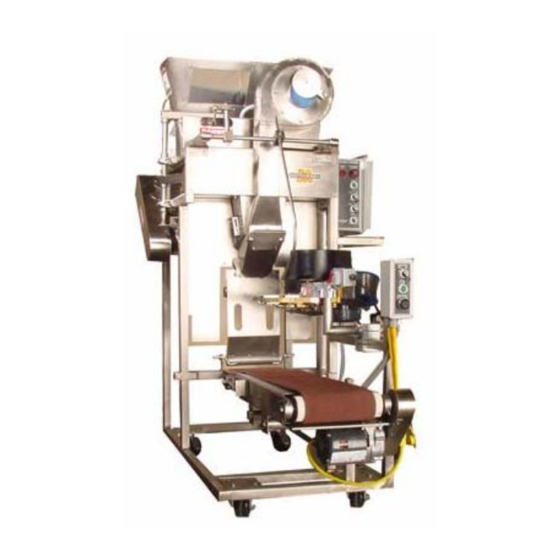
INSPECTION REPORT VISUAL: CLEANLINESS: DRUM PASS FAIL EXTERIOR PASS FAIL METAL FINISH (UNIFORM) PASS FAIL DECALS: PASS FAIL MECHANICAL: ROTATION OF MOTOR PASS FAIL LIMIT SWITCH PASS FAIL TIMING OF DRUM PASS FAIL MANUAL MODE AND AUTO PASS FAIL CHAIN: TENSION PASS FAIL... - Page 4 Brief Overview of the Operation Model VV510 Magic Finger Bagger Ice is harvested and delivered to the Hopper at the top of the Magic Finger Bagger by other conveying equipment. When the ice fills the Hopper to a level above the lower limit switch the Bagger is ready to operate in automatic mode.
-
Page 5: Installation, Maintenance, And Operation / Safety Guidelines
Installation, Maintenance, and Operation / Safety Guidelines 1. During installation or service, LOCK-OUT the power supplied to the machine to prevent accidental start-up which could cause severe injury or death. 2. NEVER operate this machine without the factory-supplied guards in place. Severe injury or death could result. -
Page 6: General Instructions
If you have questions, need installation, factory trained service, replacement parts or additional information contact your authorized dealer or Matthiesen at 1(800) 624- 8635. -
Page 7: Set-Up Instructions (Mechanical And Electrical Connections)
Set-up Instructions for Model VV510 Magic Finger Bagger UNPACKING Carefully remove equipment from crating. CONVEYOR MOUNTING Loosen the setscrews on the Conveyor Assembly support arms and flip the assembly over so the motor is below the Conveyor belt and away from the Magic Finger Bagger. CONVEYOR ELECTRICAL CONNECTION Connect the L5-15 twist-lock plug on the Conveyor motor cord to one of the receptacles on the cords from the Magic Finger Bagger pendant station. -
Page 8: Magic Finger Bagger Electrical Connection
Set-up Instructions for Model VV510 Magic Finger Bagger MAGIC FINGER BAGGER ELECTRICAL CONNECTION Before connecting the twist-lock plug from the Magic Finger Bagger Control Enclosure cord to an electrical source, push the maintained emergency stop switch, on the Control Enclosure in to make certain the machine does not start when it is connected. -
Page 9: Timing And Adjusting The Model Vv510-Mod Magic Finger Bagger
Timing and Adjusting the Model VV510 Magic Finger Bagger TIMING THE SURE-FALL MECHANISM The Magic Finger Bagger comes from the factory with the Sure-Fall timing correctly set. These instructions are given in case of a drive chain breakage or some other unusual event that affects the timing of the machine. -
Page 10: Timing And Adjusting The Model Vv510-Mod Magic Finger Bagger
Timing and Adjusting the Model VV510 Magic Finger Bagger ADJUSTING THE BAG RETAINER RODS ON THE BAG SHELF ASSEMBLY The bag retainer rods can be adjusted for different width ice bags. To adjust the bag retainer rods, item 2 on Bag Shelf Assembly drawing #0062-B, loosen the setscrews in the collar and move them to the desired position and retighten the setscrews. -
Page 11: Running Machine And Checking The Ice Bag Weight
Start-up Instructions for Magic Finger Bagger RUNNING MACHINE AND CHECKING THE ICE BAG WEIGHT After completing all of the set-up procedures outlined in this operation manual, double check that the correct bags are installed on the wicket rods and that the Gravity Weight is in place. Fill the Hopper with the same type of ice that you will be running. - Page 12 Troubleshooting the Model VV510 Magic Finger Bagger If the Magic Finger Bagger does not operate properly after completing the start-up adjustments and timing procedures please check the following before consulting the factory: The circuit breaker at the power source that supplies the Bagger is in the “ON” position. The power cord on the Control Enclosure is plugged into the proper receptacle and that power is making it to the terminal blocks, on the back panel assembly where the cord wires are connected.
- Page 13 Reducers, bearings and chain are lubricated at the factory. Because of use in wet conditions they should be inspected and lubricated accordingly. Matthiesen recommends the use of food grade lubricants on all necessary parts. Reducers and gear motors: Food grade oil...
- Page 18 2Z306F thru 2Z310F Operating Instructions & Parts Manual Please read and save these instructions. Read carefully before attempting to assemble, install, operate or maintain the product described. Protect yourself and others by observing all safety information. Failure to comply with instructions could result in personal injury and/or property damage! Retain instructions for future reference.
- Page 19 Dayton Operating Instructions and Parts Manual 2Z306F thru 2Z310F Dayton Speed Reducers ® Specifications and Performance 1725 RPM Input 1160 RPM Input 875 RPM Input Output Output Output Output Torque Max. Output Torque Max. Output Torque Max. Model Ratio In-Lb Input HP In-Lb Input HP...
- Page 20 Dayton Operating Instructions and Parts Manual Models 2Z306F thru 2Z310F Installation (Continued) (L) = “Leverage” Factor from following 7. Make final wiring connections Load Factors chart, accounting for position of (consult nameplate on motor). Loading coupling along length of speed NOTE: Output shaft may be run in Type of Moderate Heavy...
- Page 21 Dayton Operating Instructions and Parts Manual 2Z306F thru 2Z310F Dayton Speed Reducers ® Installation (Continued) shoulder or bore recess. For bearings on shafts, press on inner race only. forth to verify end play exists. If Cleaning detectable end play completely Properly selected and installed electric disappears before capscrews are motors are capable of operating for...
- Page 22 Dayton Operating Instructions and Parts Manual Models 2Z306F thru 2Z310F Troubleshooting Chart Symptom Possible Causes(s) Corrective Action Unit fails to operate 1. Blown fuse or open circuit 1. Replace fuse or reset circuit breaker breaker to motor 2. No power to motor 2.
- Page 23 Dayton Operating Instructions and Parts Manual 2Z306F thru 2Z310F For Repair Parts, call 1-800-323-0620 24 hours a day - 365 days a year Please provide the following information: -Model number -Serial number (if any) -Part description and number as shown in parts list Address parts correspondence to: Grainger Parts P.
- Page 24 Dayton Operating Instructions and Parts Manual 2Z306F thru 2Z310F Repair Parts List Reference Reference Number Description Part No. Number Description Part No. Gear housing XG20-1 Key-projecting output-XK3-3-20.5 Kit 19282 Vent plug XVP-4-18M Output bearing shim XG20-39 Pipe plugs XSHPP-4 Cover gasket XG20-45A Input ball bearing-back XBB-12-32-10M...
- Page 25 Dayton Operating Instructions and Parts Manual 2Z306F thru 2Z310F Dayton Speed Reducers ® LIMITED WARRANTY DAYTON ONE-YEAR LIMITED WARRANTY. Dayton Speed Reducers, Models covered in this manual, are warranted by Dayton Electric Mfg. Co. (Dayton) to the original user against defects in workmanship or materials under normal use for one year after date of purchase.
- Page 26 Operating Instructions & Parts Manual 2Z932F thru 2Z935F Please read and save these instructions. Read carefully before attempting to assemble, install, operate or maintain the product described. Protect yourself and others by observing all safety information. Failure to comply with instructions could result in personal injury and/or property damage! Retain instructions for future reference.
- Page 27 Dayton Operating Instructions and Parts Manual Dayton Speed Reducers ® it in the open position and tag it to NOTE: The speed reducer is intended reducer shaft sleeve. Line up prevent unexpected application of for horizontal floor, wall, or ceiling keyway in 5/8: diameter motor power.
- Page 28 Dayton Operating Instructions and Parts Manual Models 2Z932F thru 2Z935F Installation (Continued) down, Shim as required. Do not and refill with AGMA #4 gear oil. If depend on a flexible coupling to AGMA #4 gear oil is not available, use Maximum CAUTION compensate for misalignment..
- Page 29 Dayton Operating Instructions and Parts Manual 2Z932F, 2Z933F, 2Z934F and 2Z935F For Repair Parts, call 1-800-323-0620 24 hours a day - 365 days a year Please provide the following information: -Model number -Serial number (if any) -Part description and number as shown in parts list Address parts correspondence to: Grainger Parts P.
- Page 30 Dayton Operating Instructions and Parts Manual 2Z932F thru 2Z935F Repair Parts List Ref. Model 2Z932F Model 2Z933F Model 2Z934F Model 2Z935F Description Part No. Part No. Part No. Part No. Gear housing X2Z-1 X2Z-1 X2Z-1 X2Z-1 Output gear 46T (Kit 84396) 46T (Kit 84396) 41T (Kit 84399) 48T (Kit 84395)
- Page 31 2Z932F thru 2Z935F Dayton Operating Instructions and Parts Manual Service Record Dayton Speed Reducers ® Date Maintenance performed Replacement components required...
- Page 32 Dayton Operating Instructions and Parts Manual Models 2Z932F thru 2Z935F Troubleshooting Chart Symptom Possible Causes(s) Corrective Action Unit fails to operate 1. Blown fuse or open circuit breaker 1. Replace fuse or reset circuit breaker 2. No power 2. Contact power company 3.
- Page 33 2Z932F thru 2Z935F Dayton Operating Instructions and Parts Manual Dayton Speed Reducers ® LIMITED WARRANTY DAYTON ONE-YEAR LIMITED WARRANTY. Dayton Speed Reducers, Models covered in this manual are warranted by Dayton Electric Mfg. Co. (Dayton) to the original user against defects in workmanship or materials under normal use for one year after date of purchase.
-
Page 34: Wiring Diagrams
480 SERIES 482 Series Split Phase 115V > 014-482-4029 QUICK SPECS Stages OHL* Approx Voltage Weight Speed (RPM) 60 Torque (in- lbs) Input HP Ratio:1 28.6 Amps 3.97 Enclosure TEFC * Maximum overhung load on center of output shaft CAD DRAWING WIRING DIAGRAM SPECIFICATIONS Gearhead Specifications... - Page 35 Shafts: Hardened steel. Mounting: Foot, (any angle) on 482; Face (any angle) or optional footplate on 485 Gearing: AGMA class 9 heat treated steel. 1st stage helical metal, balance spur metal. Bearings: Ball Output and Needle. Motor Specifications Motor Type: Split Phase on 482;...
- Page 36 Integral Horsepower DC Motor Installation & Operating Manual 5/05 MN605...
- Page 37 Table of Contents Section 1 General Information ................Overview .
- Page 38 Humidity And Brush Wear ............... Guide To Commutator Appearance .
-
Page 39: General Information
Section 1 General Information Overview This manual contains general procedures that apply to Baldor Motor products. Be sure to read and understand the Safety Notice statements in this manual. For your protection, do not install, operate or attempt to perform maintenance procedures until you understand the Warning and Caution statements. A Warning statement indicates a possible unsafe condition that can cause harm to personnel. -
Page 40: Safety Notice
Safety Notice This equipment contains high voltage! Electrical shock can cause serious or fatal injury. Only qualified personnel should attempt installation, operation and maintenance of electrical equipment. Be sure that you are completely familiar with NEMA publication MG 2, safety standards for construction and guide for selection, installation and use of electric motors and generators, the National Electrical Code and local codes and practices. - Page 41 Section 1 General Information Safety Notice Continued WARNING: UL listed motors must only be serviced by authorized Baldor Service Centers if these motors are to be returned to a flammable and/or explosive atmosphere. WARNING: Thermostat contacts automatically reset when the motor has slightly cooled down.
-
Page 42: Receiving
Section 1 General Information Receiving Each Baldor Electric Motor is thoroughly tested at the factory and carefully packaged for shipment. When you receive your motor, there are several things you should do immediately. Observe the condition of the shipping container and report any damage immediately to the commercial carrier that delivered your motor. -
Page 43: Installation & Operation
Section 2 Installation & Operation Overview Installation should conform to the National Electrical Code as well as local codes and practices. When other devices are coupled to the motor shaft, be sure to install protective devices to prevent future accidents. Some protective devices include, coupling, belt guard, chain guard, shaft covers etc. -
Page 44: Doweling & Bolting
Section 1 General Information Doweling & Bolting After proper alignment is verified, dowel pins should be inserted through the motor feet into the foundation. This will maintain the correct motor position should motor removal be required. (Baldor motors are designed for doweling.) Drill dowel holes in diagonally opposite motor feet in the locations provided. -
Page 45: Thermostats
Section 1 General Information Figure 2-1 Encoder Connections Color Codes for Optional Baldor Encoder Cable Electrically Isolated Encoder COMMON Standard Receptacle MS3112W12−10P Standard Plug MS3116J12−10S Thermostats The thermostat is a pilot circuit device used in a protective relay circuit. The thermostat ratings are given in Table 2−3. - Page 46 Section 1 General Information Figure 2-1 View from Air Inlet (Motor is on Opposite Side) Air Inlet Housing Impeller Blades Airflow Table 2−4 Electrical Data - Forced Ventilation Blower Units Size Motor Frame Volts Phase Amps 1/40 3000 3450 115/230 50/60 2.6/1.3 210-250...
-
Page 47: Coupled Start-Up
Section 1 General Information Coupled Start-Up After the first successful no load start-up, stop the motor and assemble the coupling. Align the coupling and be sure it is not binding in any way. The first coupled start-up should be without load. Check to see that the driven equipment is not transmitting any vibration back to the motor through the coupling or the base. - Page 48 Section 1 General Information 2-6 Installation & Operation MN605...
-
Page 49: Maintenance & Troubleshooting
Section 3 Maintenance & Troubleshooting General Inspection Inspect the motor at regular intervals, approximately every 500 hours of operation or every 3 months, whichever occurs first. Keep the motor clean and the ventilation openings clear. The following steps should be performed at each inspection: Check that the motor is clean. -
Page 50: Lubrication & Bearings
Lubrication & Bearings Bearing grease will lose its lubricating ability over time, not suddenly. The lubricating ability of a grease (over time) depends primarily on the type of grease, the size of the bearing, the speed at which the bearing operates and the severity of the operating conditions. -
Page 51: Lubrication Procedure
Table 3-5 Bearings Sizes and Types Bearing Description Frame Size (These are the “Large” bearings (Shaft End) in each frame size) NEMA (IEC) Bearing Width Weight of Volume of grease D mm B mm Grease to to be added add * add * tea- oz (Grams) -
Page 52: Brush Replacement
Brush Replacement Do not change brush grades or suppliers without first contacting Baldor for technical assistance. Brush life will vary greatly due to motor load conditions and the operating environment. The brush pigtail leads should be checked for secure connection to the brush support stud. -
Page 53: Carbon Brushes For Special Operating Conditions
Carbon Brushes For Special Operating Conditions Sometimes, there are problems if motor operation requires a different design or grade of carbon brush than what was installed when the motor was built. These special operating conditions include long periods of operation with loads that are significantly greater or less than rated load capacity. -
Page 54: Guide To Commutator Appearance
Section 1 General Information Guide To Commutator Appearance Light Film: Indicates good brush Medium Film: Is the ideal commutator Heavy Film: Results from high load, high performance. Light load, low humidity, condition for maximum brush and humidity or heavy filming rate grades. Colors brush grades with low filming rates, or film commutator life. -
Page 55: Commutator
Section 1 General Information Commutator After several hours of operation, the commutator surface under the brush should take on a darker bronze color. This is due to self-generated film caused by normal commutation. This coloration should be even, without blotches or black areas. A shiny copper color or black streaks in the brush tracks are signs of improper commutation or contamination by a foreign material. -
Page 56: Turning The Commutator
Section 1 General Information Turning The Commutator After commutator turning, check its run-out with the bearings on V blocks. For all commutators, maximum run-out is .002″. New and minimum commutator diameters are listed as follows. Commutator Brush Track Diameters Frame New Motor Commutator Minimum Diameter after Diameter (inches) -
Page 57: Field Coil Overheating
Section 1 General Information Field Coil Overheating The blowers or external cooling systems should be left in operation if the main field windings remain fully energized with the motor at standstill. Failure to do so may cause too much heat build-up which could cause reduced insulation life. When using field economy circuits to reduce voltage to the main fields during standstill, blowers do not need to be operating. -
Page 58: Troubleshooting Chart
Section 1 General Information Table 3-6 Troubleshooting Chart Symptom Symptom Possible Causes Possible Causes Possible Solutions Possible Solutions Motor will not start Usually caused by line trouble, such Check source of power. Check overloads, fuses, as, single phasing at the starter. controls, etc. -
Page 59: Accessories
Accessories The following list shows some accessories available through Baldor’s Mod Express or available on custom manufactured motors. Contact your Baldor supplier for information on each additional accessory or those listed below. Bearing RTD RTD (Resistance Temperature Detector) devices are used to measure or monitor the temperature of the motor bearing during operation. -
Page 60: Reflash Instructions
Tachometers: DC, AC and digital outputs are available. These can be mounted to our motors or shipped separately. Tachs help the SCR control achieve more precise speed regulation than by armature feedback alone. Transparent Brush Inspection: For easy brush inspection and commutation monitoring without disassembly of the motor. - Page 61 Section 4 Connection Diagrams Low Voltage connection Shunt Field High Voltage connection Shunt Field Field Reversing Series Motor Interpole Series Field Interpole Series Field Armature Armature − − Series Motor CW Rotation Series Motor CCW Rotation (Facing Commutator End) (Facing Commutator End) Armature Reversing Compound and Stabilized Motors Shunt Field...
- Page 62 Field Reversing Shunt Motor Shunt Field Interpole Armature − Shunt Motor CCW Rotation (Facing Commutator End) High Voltage Field Connection Field Reversing Shunt Motor Shunt Field Interpole Armature − Shunt Motor CW Rotation (Facing Commutator End) High Voltage Field Connection DC Generator Connection Diagram Compound Wound Short Shunt Connection Shunt Field...
- Page 63 Baldor District Offices UNITED STATES FAX: 586−978−9969 TEXAS CHINA MICHIGAN Continued HOUSTON SHANGHAI JIAHUA BUSINESS CENTER ARIZONA GAND RAPIDS 4647 PINE TIMBERS ROOM NO. A−8421 PHOENIX 668 3 MILE ROAD NW SUITE # 135 808 HONG QIAO ROAD 4211 S 43RD PLACE GRAND RAPIDS, MI 49504 HOUSTON, TX 77041 SHANGHAI 200030...
- Page 64 BALDOR ELECTRIC COMPANY P.O. Box 2400 Ft. Smith, AR 72901- -2400 (479) 646- -4711 Fax (479) 648- -5792 © Baldor Electric Company Printed in USA MN605 5/05...
- Page 65 Spare Parts List Item Assembly Matthiesen Description dwg # Part # Wicket Rod Weldment B0000 MFBAGR032 Chain Tensioner B0000 MFBAGR166 Extension Spring B0000 MFBAGR182 Cam Follower B0000 MFBAGR016 V Belt B0000 VB027 Bottom Proximity Switch B0041 PT927 Top Proximity Switch...
- Page 77 MAGIC FINGER PARTS LIST Item QTY REF # DESCRIPTION PART # B-0041-A Std Hopper Assembly S.S. MFBAGR104 B-0041-A Top Hopper UHMW Liner BAGR426 B-0042-B Blower Assembly S.S. – 120/1/60 MFBAGR209 B-0043-A Magic Finger Assembly S.S. MFBAGR102 B-0044-B Sure-Fall Assembly S.S. MFBAGR012 B-0045-A Drum, Volumetric, Assembly, SS MFBAGR211...
- Page 78 P-000049 ¾ HP Motor MTR325 3.66 P-000029 Roller Chain #40 ½ Pitch VB057 P-000030 Roller Chain Connecting Link #40 ½ Pitch PT059 P-000050 HD Roller Chain Tensioner #40 MFBAGR166 P-000051 Extension Spring .105Ø wire x 1.00 OD x 7.5” LG MFBAGR095 P-000052 4”Ø...
- Page 79 F0500004 SS ”Ø Flat Washer 5/16 F0401024 SS Hex Head Cap Screws ¼”-20 UNC-2A x 1.5” LG F0601020 SS Hex Head Cap Screws -16 UNC-2A x1.25” LG 3/8” SS Keyway ⅜x12” LG P-000045 P-000033 SS Keyway x12” LG 3/16 P-000060 Nylon Tie Cable P-000059 RTV Black Silicone...
- Page 80 10 X 36 SS Conveyor Assembly Individual Parts List APPENDIX A Item DESCRIPTION PART # 3 x 12 Idler Pulley MFBELT001 3 x 12 Drive Pulley MFBELT002 2” Spring Loaded Idler Pulley MFBELT003 ¾ x 18 Drive Shaft MFBELT004 ¾ x 16- ½ Idler Shaft MFBELT005 SS Conveyor Support Arm MFBELT009...
- Page 82 CLEANING AND SANITIZING INSTRUCTIONS Equipment: The Matthiesen Magic Finger Bagger Materials Required Water hose with spray nozzle attached to potable water source. Pressurized detergent spray unit with application hose and spray nozzle. Portable, hand operated pressure sprayer (2-3 gallon size).
- Page 83 90 DAYS WARRANTY ON ALL PARTS: 90 Days from date of purchase to the original purchaser, MATTHIESEN will at it’s election, repair or replace at our factory in San Antonio, Texas, such part or parts found by the manufacturer to be defective. Any part or parts of equipment sent to us for adjustment, repair or replacement, will be shipped with all transportation charges prepaid, and will be returned to the customer with all transportation charges collect.
- Page 84 DECAL REORDER SHEET DECAL NUMBER DECAL IDENTIFICATION D001 ......................D002 ........................D003 ....................D004 ....................D005 .........................
- Page 85 DECAL REORDER SHEET DECAL NUMBER DECAL IDENTIFICATION D006 ........D007 ......................... D008 ....................D009 ......................
Need help?
Do you have a question about the MAGIC FINGER VV510 and is the answer not in the manual?
Questions and answers