
Summary of Contents for iGrid T&D iRTU Series
- Page 1 iRTU, iGW & iRTUe iRTU, iGW & iRTUe Series Series User Manual User Manual June 2017 June 2017 Revision 2 Revision 2...
- Page 2 User Manual User Manual iGrid T&D is a specialized company in the development of electrical facility control applications, with a iGrid T&D is a specialized company in the development of electrical facility control applications, with a wide experience in the power industry. wide experience in the power industry.
- Page 3 User Manual User Manual This publication includes information icons that point out important information. It also includes tip This publication includes information icons that point out important information. It also includes tip icons to point out useful information to the reader. The corresponding icons should be interpreted as icons to point out useful information to the reader.
- Page 4 User Manual Please read these instructions carefully and familiarize yourself with the product prior to installation, operation, servicing and/or maintenance. The user is responsible for verifying that characteristics stated for the product are suitable for the application. The user is responsible for reading and following the installation and operation instructions prior to commissioning and maintenance.
- Page 5 User Manual All iRTU & iGW Series products are supplied with a license that sets the communication capabilities of the device in terms of number of supported devices (IEDs and control centers), maximum number of points and used protocols. The license also defines advanced functionalities such as hot-standby redundancy, PLC and file transfer functionalities.
- Page 6 Abbreviations ................................3 Equipment operation ..............................4 Electrical connections ..............................4 2.1. iRTU Series: RTUs for Substation Automation and Telecontrol of MV grids ..........14 2.1.1. Product main features ..........................14 2.1.2. Product models ............................15 2.2. iGW Series: versatile communication gateways for electrical facilities ............18 2.2.1.
- Page 7 User Manual 6.1.7. Configuration and maintenance ......................41 7.1.1. Serial communication ports ........................44 Serial port COM1 pinout ....................... 44 Serial port COM2 pinout ....................... 44 Serial ports DIP switch ........................44 RS485 (2-wires) connection considerations ................44 7.1.2. Ethernet communication ports ........................ 44 7.1.3.
- Page 8 User Manual S3 Series includes IEEE 802.1d RSTP (Rapid Spanning Tree Protocol). Two options of power supply: Wide range power supply: 32 - 250Vdc / 80 - 250Vac (2.5kVrms isolation). 24 Vdc power supply: 19.5-60Vdc (2.5kVrms isolation). ...
- Page 9 User Manual (1) MicroSD internal slot for data storage. The redundant Ethernet ports of the S3 modules are available with the following interfaces: Optical interface with SC or ST connectors, multimode fiber (62.5/125 µm and 50/125 µm) and 1300 ...
- Page 10 User Manual - Ethernet 10/100BaseTX port (RJ45 connector) - Redundant Ethernet 100BaseFX ports (ST, SC or SFP) M0: GPRS, - Built-in dual-SIM 4G/3G/GSM/GPRS modem M1: 3G, M2: 4G (LTE) - USB port (USB A connector) - MGMT port (miniUSB connector) Table 4 – iGW units: available models and configurations Index ─...
- Page 11 User Manual devices are auxiliary equipment for the iRTU and iGW units that allow to expand their acquisition and command capabilities in order to suit the requirements of each application and facility. iRTUe units are equipped with one serial port (EXP422 port) for communication with iRTU & iGW units and other iRTUe I/O modules via RS422 straight cable.
- Page 12 User Manual Amber Link activity Green Link established MGMT port activity STATE Blinking red (every USB port activity (reading and writing operations) 100 ms) Power ON Green iKernel update process. See section 18. iKernel update process. See section 18. iKernel update process. See section 18. Green iKernel ...
- Page 13 User Manual The iRTU-S3 series products combine the excellent performance of the iRTU units and state-of-the-art switch technology with IEEE 802.1d RSTP (Rapid Spanning Tree Protocol) redundancy. This provides a modular, flexible, and economical solution for bay controlling. Internally the iRTU and switch modules are designed to work as independent devices. Therefore, the switch operation will not be affected by a failure in the remote telecontrol module (for example, due to a configuration error of the RTU database), and vice versa.
- Page 14 User Manual ETH4 & ETH5 ports 10/100BaseTX Ethernet ETH5 ETH4 ports with RJ45 connector port LEDs port LEDs Power supply COM3 port EXP422 port Grounding Basic RS232/RS485/RS422 RS485/RS422 port Terminal Connection to iRTUe units Figure 33 – Bottom view of an iRTU-S3 unit Figure 34 – iRTU-S3D1 unit with ST connectors Index ─...
- Page 15 User Manual The model depicted in Figure 35 is iRTU-S3C1 including 8 digital inputs, 4 relay outputs and 2 analog inputs: Condition indicator LEDs Analog inputs Reset button Configuration Digital inputs microswitch PC management port USB Host connection Relay outputs Figure 35 – Front view of an iRTU -S3 unit (model S3C1) Index ─...
- Page 16 User Manual The model depicted in Figure 36 is iRTU-S3D1 including 24 digital inputs: Condition indicator LEDs Reset button Configuration Digital inputs microswitch PC management port USB Host connection Figure 36 – Front view of an iRTU -S3 unit (model S3D1) Index ─...
- Page 17 User Manual Same characteristics as the iRTU- B0 devices’ serial ports. Refer to section 5.1.1 for details. Same characteristics as the iRTU- B0 devices’ COM1 serial port. Refer to section 5.1.1.1 for details. Same characteristics as the iRTU- B0 devices’ COM2 & COM3 serial ports. Refer to section 5.1.1.2 for details.
- Page 18 User Manual This section describes the LED functions of the iRTU-S3 units with and later. In order to verify the iAppManager version of your device, follow the steps described in ANNEX I. Contact iGrid T&D (sat-bcn@igrid-td.com ) in case of doubts. Table 14 summarizes the functions of the iRTU-S3 front panel LEDs, which provide indication of operating conditions and communication signals.
- Page 19 User Manual The model depicted in Figure 46 is iRTU-MxD1 (x = 0, 1 or 2) equipped with 24 digital inputs: Condition indicator LEDs Reset button Configuration Digital inputs microswitch PC management port USB Host connection Figure 46 – Front view of iRTU-MxD1 units Index ─...
- Page 20 User Manual iRTU-M0, iRTU-M1 & iRTU-M2 units include 3 serial ports available to communicate with Control Centers and IEDs: COM2 & COM3: basic RS232/RS422/RS485 serial ports, software configurable. RS232 is basic with 5 lines. EXP422: RS422/RS485 serial port, software configurable. EXP422 port is used to connect to iRTUe ...
- Page 21 User Manual Refer to section 5.1.5 for details on I/O configuration of iRTU-M0, iRTU-M1 & iRTU-M2 units. This section describes the LED functions of the iRTU-M0, iRTU-M1 & iRTU-M2 units with and later. In order to verify the iAppManager version of your device, follow the steps described in ANNEX I. Contact iGrid T&D (sat-bcn@igrid-td.com ) in case of doubts.
- Page 22 User Manual iRTU-M0, iRTU-M1 & iRTU-M2 models support two SIMs which can be internal or external to the unit. Internal SIMs can only be accessible by removing the bottom lid of the device (Figure 47). Figure 47 –Internal SIM card location in an iRTU-M0C1 unit (single SIM) Figure 48 shows an iRTU/iGW unit with dual-SIM support: Figure 48 - Dual-SIM card In order to insert the SIM card, press the yellow button and pull off the lid of the SIM card holder.
- Page 23 (iGW-B0, iGW-S3, iGW-M0, iGW-M1 & iGW-M2) series products. They are intended to be used to: iGW (iGW-B0, iGW-S3, iGW-M0, iGW-M1 & iGW-M2) series products. They are intended to be used to: increase the I/O capability of the iRTU series products, increase the I/O capability of the iRTU series products, ...
- Page 24 User Manual User Manual Power Power Grounding Grounding iRTUe address iRTUe address supply supply Terminal Terminal configuration microswitch configuration microswitch Figure 54 Figure 54 – – Top view of an iRTUe Top view of an iRTUe unit unit EXP422 port EXP422 port RS485/RS422 port RS485/RS422 port Figure 55...
- Page 25 User Manual User Manual Card A LEDs Card A LEDs Digital inputs Digital inputs Digital inputs Digital inputs (Card B) (Card B) (Card A) (Card A) Card B LEDs Card B LEDs Figure 56 Figure 56 – – Front view of an iRTU Front view of an iRTU e-D1D1 device e-D1D1 device Index...
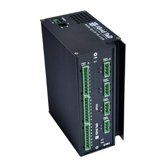
- Page 26 User Manual User Manual Card A LEDs Card A LEDs Relay outputs Relay outputs Digital inputs Digital inputs (Card B) (Card B) (Card A) (Card A) Card B LEDs Card B LEDs Figure 57 – – Front view of an iRTUe-D1R1 Figure 57 Front view of an iRTUe-D1R1 device device Index...
- Page 27 User Manual User Manual Figure 187 - Redundancy states examples (IV) Figure 187 - Redundancy states examples (IV) actOK actOK ( ( ActiveOK ActiveOK ) : iRTU/iGW has ): iRTU/iGW has Active Active role and communicates with its peer, which has a role and communicates with its peer, which has a Standby Standby ...
- Page 28 User Manual User Manual Figure 190 - Redundancy states examples (VII): upper image s Figure 190 - Redundancy states examples (VII): upper image s hows the status in the hows the status in the active active unit when it performs a switchover. Lower image shows the s unit when it performs a switchover.
- Page 29 User Manual Figure 191 - Redundancy states examples (VIII): status in a standby unit which has performed a switchover. Below is a description of some of the main redundancy statuses for the peer unit: Unknownstate: the state of the peer unit is unknown. ...
- Page 30 User Manual bckSwitchReady (Standbyswitchoverready): this indicates that the peer unit (which is Standby) is ready for a switchover. bckSwitching(Standbyswitching ): peer unit is switching to the Active role. The above states corresponds to the following numerical values: unknownstate: state 0 Booting: state 1 Hearing: state 2 actAlone: state 10...
- Page 31 User Manual Configure column Tag using the following identifiers: #rdcy.IamActive, #rdcy.IamPrimary , #rdcy.SwitchOverReady, #rdcy.MyState and #rdcy.PeerState (refer to Figure 193). Figure 193 - Definition of internal signals #rdcy.IamActive, #rdcy.IamPrimary, #rdcy.SwitchOverReady, #rdcy.MyState and #rdcy.PeerState in the iRTU/iGW database using the iConf configuration tool The states/values for these internal points are as follows: ...
- Page 32 User Manual 45: bckSwitchCloseingClient (Standbyswitchoverclosingclient ) 49: bckWaitReset (Standbywaitreset ) 50: bckReboot (Standbyreboot ) Figure 194 shows an example of State type definition for #rdcy.IamActive, #rdcy.IamPrimary, and #rdcy.SwitchOverReady tags in iConf: Figure 194 – Example of definition of Statetype for #rdcy.IamActive, #rdcy.IamPrimary, and #rdcy.SwitchOverReady tags using iConf tool Figure 195 shows an example of Statetype ...
- Page 33 User Manual Figure 195 - Example of definition of Statetype for #rdcy.MyState and #rdcy.PeerState tags using iConf tool When using direct serial link, interconnect redundant iRTU/iGW units via RS422 using the following cable layout: Rx – Rx – Tx – Tx – Table 23 – RS422 cable pin layout between redundant iRTU/iGW units Index ─...
- Page 34 User Manual In this section we will see how to check the iRTU & iGW devices’ iKernel version and, if required, how to update it. Generally, all iRTU & iGW devices delivered in 2017 and later, include iKernel versions 2.9.0 and later. The exact iRTU &...
- Page 35 User Manual Accessing the iRTU/iGW iDevSetup menu (15.4.1) and selecting the “Showsysteminfo ” option. This option retrieves not only the iKernel version, but also the iDevSetup version, the RTC chip model and the Ethernet switch model and status. Refer to section 15.4.2.3 for further details. Enter command info ...
- Page 36 User Manual Figure 198 – iDevSetup menu: Update iKernel option (key “k”) 7) Press “y” to start the update process. Do not disconnect the USB drive during the update process. Do not remove the power supply during the update process. 8) During this process, the console shows some messages about the update status: Figure 199 –...
- Page 37 User Manual The Fieldusertest is a guided test intended to be used by users at field. In order to perform the field user test, user should access the iRTU/iGW iDevSetup menu (section 15.4), select option “4” (Executefactorytest , section 15.4.2.4), and then press key “m” (15.4.2.4.1) . The FieldUsertest ...
- Page 38 User Manual UNE-EN 60068-2-38 10 days test with cycles from 24ºC to 65ºC with 93%RH IEC 60068-2-6 2g acceleration 9 to 350 Hz IEC 60068-2-27 15 g 11 ms Table 25 – iRTU & iGW Type Tests Index ─ ─ 21. iRTU & iGW series type tests...
- Page 39 User Manual This section describes ordering information for all iRTU & iGW Series products: (4) serial ports (2.5 kVrms isolation) with TX/RX LED indicators: (1) Full RS232/RS422/RS485 serial port, software configurable (COM1 port). (2) Basic RS232/RS422/RS485 serial ports, software configurable (COM2 & COM3 ...
- Page 40 User Manual options: power supply: 32 - 250Vdc / 80 - 250Vac. power supply: 19.5-60Vdc. Power supply options: : 19.5 - 60 Vdc : 32 - 250 Vdc / 80 - 250 Vac Pre-installed internal industrial microSD card for data storage (optional): 8GB (SDCIT/8GBSP by Kingston or equivalent) ...
- Page 41 User Manual (1) MicroSD internal slot for data storage. options: power supply: 32 - 250Vdc / 80 - 250Vac. power supply: 19.5-60Vdc. options: : 24 digital inputs. : 8 digital inputs, 4 relay outputs and 2 DC current analog inputs. nominal voltage options: ...
- Page 42 User Manual Equipped with , with support: : GPRS modem : 3G modem : 4G (LTE) modem (3) serial ports (2.5 kVrms isolation) with TX/RX LED indicators: (2) Basic RS232/RS422/RS485 serial ports, software configurable (COM2 & COM3 ...
- Page 43 User Manual Includes the following terminal blocks: (1) MSTB 2,5/ 3-ST-5,08 (code no.: 1757022) for Power Supply. (1) MC 1,5/ 9-ST-3,5 (code no.: 1840434) for COM1 serial port. (2) MC 1,5/ 5-ST-3,5 (code no.: 1840395) for COM2 and COM3 serial ports. ...
- Page 44 User Manual Includes the following terminal blocks: (1) MSTB 2,5/ 3-ST-5,08 (code no.: 1757022) for Power Supply. (2) MC 1,5/ 5-ST-3,5 (code no.: 1840395) for COM2 and COM3 serial ports. (1) MC 1,5/ 6-ST-3,5 (code no.: 1840405) for EXP422 serial port ...
- Page 45 User Manual Includes the following terminal blocks: (1) MSTB 2,5/ 3-ST-5,08 (code no.: 1757022) for Power Supply. (1) MC 1,5/ 6-ST-3,5 (code no.: 1840405) for EXP422 serial port. (4) MVSTBR 2,5/ 4-ST-5,08 (code no.: 1792265) for relay outputs. ...
- Page 46 User Manual In order to verify if iAppManager application version is 3.0.0, a USB flash drive is required. ≥ These are the steps to follow to check the iAppManager version using a USB flash drive: N.B:Beforestarting,please,ensurethatthereisnotanyUPLOAD_CONForUPLOAD_BINfolderinthe USBdrive. 1) Connect the USB drive to the USB port in the iRTU/iGW unit. 2) After 10-15 seconds, remove the USB drive from the iRTU/iGW unit and connect it to a USB port in the PC.
Need help?
Do you have a question about the iRTU Series and is the answer not in the manual?
Questions and answers