Table of Contents
Advertisement
Quick Links
Advertisement
Table of Contents

Related Manuals for Sinnis motorcycles T380


Summary of Contents for Sinnis motorcycles T380
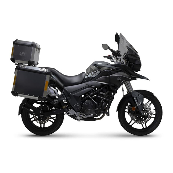
- Page 1 51�15 MOTORCYCLES https://www.motomanuals.net/...
-
Page 2: Preface
PREFACE Thank you for buying a new Sinnis Motorcycle. Please read this manual carefully before using your Sinnis. It contains important information on the function, operation and maintenance of the bike that will help the owner to keep it running safely and reliably and maintain its value. -
Page 3: Safety Information
INFORMATION For your own safety and that of others, please strictly follow the safety information and operating instructions provided, and pay particular attention to the safety warning symbols shown below when given: Indicates a potential high-risk hazard that may cause serious permanent injury or DANGER death if the instructions or advice are not followed. -
Page 4: Table Of Contents
CONTENTS Preface Running-In Safety information Safe riding guide Periodic maintenance Content Precautions for use Engine oil Air filter Vehicle identification number Introduction to the motorcycle Spark plugs Ignition Switch/Steering lock Throttle adjustment Instrument warning lights Front brake inspection Left-hand switches Rear brake inspection Right-hand switches Tyres and wheels... -
Page 5: Precautions For Use
USER’S NOTICE Read through this manual carefully and thoroughly. DANGER CAUTION 1.Strictly follow all traffic laws and regulations. 1.Valve clearances must be checked and adjusted by a 2.Do not ride this motorcycle without a valid motorcycle Sinnis approved professional workshop mechanic in license. -
Page 6: Vehicle Identification Number
USER’S NOTICE Vehicle Identification Number(VIN) and Engine Number 3. The engine number 1. The vehicle identification 2. The VIN plate number (VIN) is stamped is stamped on the top is on the right-hand side of on the right-hand side of of the crankcase on the frame. -
Page 7: Introduction To The Motorcycle
USER’S NOTICE Introduction to the motorcycle - Location of parts, rider's view 1. Rear-view mirror 2. Left handlebar 3. Left switch housing 4. Instrument cluster 5.Ignition switch 6.Right switch housing 7. Throttle Grip 8. Fuel tank filler cap . 6 . https://www.motomanuals.net/... - Page 8 USER’S NOTICE Location of parts - left-hand side 1. Headlight 2. Front forks 3. Seat 4. Seat lock 5. Gear-change lever 6. Rider's footrest 7. Passenger footrest 8. Luggage . 7 . https://www.motomanuals.net/...
- Page 9 USER’S NOTICE Location of parts - right-hand side 1. Tail light 2. Fuel tank 3. Rear wheel 4. Exhaust silencer 5. Passenger footrest 6. Rider's footrest 7. Rear brake pedal 8. Front wheel . 8 . https://www.motomanuals.net/...
-
Page 10: Ignition Switch/Steering Lock
USER’S NOTICE Ignition lock The ignition switch operates the ignition system and steering steeringlock as below: Name Instruction T urn the ignition key to position to 1.Ignition provide power for the ignition. In this switch ON position the key cannot be removed. T urn the ignition key to position to 2.Ignition... -
Page 11: Instrument Warning Lights
USER’S NOTICE Instrument Cluster Instruction Name The functions of Instrument console are as below: 1.Tachometer Displays the engine speed (RPM). Ign ON: Press mode to change mpg/ av.mpg/av.mph/max.mph. Press & hold mode/select buttons to set clock, release when digits flash and change using mode button, switching between hours/mins with 2.Mode select button. -
Page 12: Left-Hand Switches
USER’S NOTICE Left Hand switches Name Instruction When overtaking the "PASS" switch can be used to warn the vehicle 1.Pass switch in front. Press the switch to turn the high beam light on. Release the switch to turn the high beam light off. Turn the switch to high beam. -
Page 13: Right-Hand Switches
USER’S NOTICE Right Handlebar Controls Name Instruction Turn the switch to position to stop the engine. 1.Engine Turn the switch to position position ON/OFF before starting the engine. switch Turn switch to to turn on headlight,turn switch to 2.Illuminating turn on instrument switch lights,taillight and position light,turn switch to... -
Page 14: Fuel Tank
10%, otherwise it can have a detrimental effect on the motorcycle. Sinnis Trading International Ltd cannot responsibility of Sinnis Motorcycles. assume liability for any damage caused by the use of the wrong fuel. -
Page 15: Motorcycle Controls
USER’S NOTICE Operation controls This motorcycle has both front and rear disc brakes. Please ensure to properly clean and maintain the brake system for the safety and reliability of your motorcycle. Name Instruction Activates the front wheel brake 1.Front brake lever Activates the rear wheel brake 2.Rear brake... - Page 16 USER’S NOTICE Operation controls Name Instruction Push the button to use 3.Electric the electric starter starter button This bike 6-speed transmission 4.Gear-shift standard one-down, pedal five-up pattern shown in the picture. ADVICE 1. This bike has a manual wet multi- plate clutch.
- Page 17 USER’S NOTICE Operation controls Name Instruction Twist the grip back to open the 5.Throttle throttle, twist it forwards to twist grip close the throttle. The tools provided enable you to do some simple adjustment and maintenance. The kit contains: 8 and 10 mm spanners, Spark plug socket, 6.Tool kit Screwdriver handle with...
-
Page 18: Load Limit
USER’S NOTICE Loading limit This bike is limited to one driver and one passenger. Strictly follow the load limits given below, otherwise the safety and stability of the motorcycle will be affected. Total Max.load of motorcycle:150kg. The load of the aluminium top box and each side box is 5kg. -
Page 19: Electronic Fuel Injection (Efi) System
USER’S NOTICE EFI (electronic fuel injection) system The primary function of the EFI system is to atomise the fuel and mix it with air before it enters the combustion chamber. The EFI system consists of the electronic control unit (ECU), injector, throttle, inlet air pressure sensor, engine temperature sensor, ignition coil, crankshaft position sensor and oxygen sensor. - Page 20 USER’S NOTICE EFI system EFI schematic 24X trigger timing Idle Control Valve Wheel on Crankshaft Throttle Position Sensor Optional Crankshaft Position Sensor alarm Throttle Optional Heated Exhaust Gas Oxygen Sensor Ignition Coil Engine Temperature Sensor Engine Control Module Inlet RE58 nozzle (left cylinder) Pressure Sensor RE58 nozzle (right cylinder) Neutral Switch...
- Page 21 USER’S NOTICE EFI system Function Introduction and Installation Position 1.Electronic Control Unit (ECU): Collects 3.Fuel injector: Atomises the fuel and injects it into the combustion chamber. and processes information and issues instructions. 2.Throttle valve assembly: Adjusts air intake 4.Fuel pump: Supplies fuel at the correct pressure.
- Page 22 USER’S NOTICE EFI system Function Introduction and Installation Position 7.Oxygen Sensor : Measures oxygen 5. Inlet pressure Sensor- measures air pressure in the inlet duct content of exhaust gases. 8.Crankshaft Position Sensor: measures 6.Ignition coil: Provides high voltage to crankshaft position speed, sends...
- Page 23 USER’S NOTICE EFI system Function Introduction and Installation Position 9.Engine Temperature Sensor: Measures engine 10.Solenoid valve for carbon canister: Controls coolant temperature flow of fuel vapour through the carbon canister. CAUTION 1.Do not disconnect the ECU or other EFI components when the ignition switch is turned ON. 2.Do not tamper with the EFI components and wiring during removal or installation.
-
Page 24: Pre-Ride Checks
OPERATION RECOMMENDATION INSPECTION BEFORE RIDING To ensure your safety, check the following items before Check the headlights, tail and brake lights, turn signals and horn are functioning correctly. riding. Item Inspection Fuel system Check you have enough fuel. Check for fuel leakage. Engine oil Check oil level is above the minimum mark. -
Page 25: Starting And Warm-Up
OPERATION RECOMMENDATION Starting and warm-up When using the electric start, each starting attempt should not exceed 5 seconds. Wait for 10 seconds before trying to start the engine again. If the engine cannot be started within 3 attempts, check the motorcycle. - Page 26 OPERATION RECOMMENDATION Starting and warm-up 3.With the throttle closed press the electric starter button. 4.Warm the engine for 3~5 minutes at idle speed before riding. WARNING To protect the engine from excessive wear after a cold start, allow the engine to warm up before riding and do not use excessive amounts of throttle until the engine reaches normal operating temperature.
-
Page 27: Riding Instructions
OPERATION RECOMMENDATION Riding operation 1.After starting and warm-up, make sure the side stand is in the up position. Pull the clutch lever in and hold it in whilst you push the gear lever down with your left foot to select 1st gear. -
Page 28: Running-In
OPERATION RECOMMENDATION Operation for new vehicle After buying a new motorcycle, the engine must be run in. The running in period is very important for a new engine, and not doing so correctly can increase engine wear and reduce reliability. For the first 600 miles keep the engine speed below 6000 RPM in all gears, do not use full throttle, avoid labouring the engine by using the gearbox, and avoid riding at the same speed for long distances. -
Page 29: Safe Riding Guide
OPERATION RECOMMENDATION Guide for safe riding 1.Guidance for riding up and down slopes When riding up and down hills or slopes, change gear according to the situation to avoid overloading or over-revving the engine. ①. When riding up steep slopes, use lower gears to keep engine speed up. ②. - Page 30 OPERATION RECOMMENDATION Guide for safe riding 4.Guidance for riding and braking When riding at high speeds, braking distances are increased. It is important to be aware of braking and stopping distances. ①. Rain or fog may cause low visibility and make the road surface slippery, which will reduce the amount of grip when braking.
-
Page 31: Periodic Maintenance
MAINTENANCE Maintenance schedule (also see Inspection before riding items) Odometer reading (miles) TIMES Every 600 miles Every Remark ITEMS 4000 miles or 1 year 8000 miles or 1 year ※ Inspect/adjust Valve clearance Inspect/adjust Inspect/adjust 0.05mm 1.※※: +-0.01mm bearing Spark plug ※... -
Page 32: Engine Oil
MAINTENANCE Engine oil level check, oil and filter change 1. To check the oil level: Support the bike upright on center stand. Run the engine for a few minutes then stop it and Engine oil level must be checked regularly allow the oil level to stabilise for 3 minutes. - Page 33 MAINTENANCE 3. Fit a new copper sealing washer onto the drain plug, then fit and tighten the plug. 4. Smear some new oil onto the rubber seal on the new filter, then fit and tighten the filter using a filter socket, or tighten as much as possible by hand - do not use a filter removal strap to tighten the filter.
-
Page 34: Air Filter
MAINTENANCE Air cleaner cleaning/replacement A dirty air filter will restrict the flow of air and lead to reduced performance and increased fuel consumption. Check, clean and replace the air filter according to the maintenance schedule. Remove the seat, then undo the air filter cover screws and remove the cover. -
Page 35: Spark Plugs
MAINTENANCE Spark plug inspection and adjustment 1. Pull the spark plug cap off the plug, then unscrew the plug using a spark plug socket. 2. Fit the new spark plug and tighten to the torque setting given below. 3. To clean a plug between replacement intervals use a soft wire brush to remove any deposits. -
Page 36: Throttle Adjustment
MAINTENANCE Throttle cable inspection and adjustment Check for a small amount of freeplay in the throttle twistgrip before the throttle opens. If the freeplay is greater or less then the specified amount adjust it as follows: Ease the rubber boot off the adjuster then slacken the locknut. -
Page 37: Front Brake Inspection
MAINTENANCE Front brake inspection If there is excessive free travel in the brake lever before the brakes come on take the bike to a Sinnis dealer. Check the fluid level in the reservoir inspection window and do not let it drop below the LOWER line. When the fluid is low check the brake pads for wear, and have new pads fitted by a Sinnis dealer. -
Page 38: Rear Brake Inspection
MAINTENANCE Rear brake inspection If there is excessive free travel in the brake pedal before the brake comes on take the bike to a Sinnis dealer. 2. Regularly check the brake pads for wear. Check the fluid level in the reservoir inspection window and do not let it drop below the LOWER line - the reservoir is behind the right-hand side cover. -
Page 39: Tyres And Wheels
MAINTENANCE Wheel inspection Tyre wear limits Front wheel 2.0mm Tyre wear limits Rear wheel 3.0mm Wheel runout limits Axial 2.0mm Runout limit Radial 2.0mm DANGER 1. Check tyre pressures regularly, preferably before every ride. 2. Too much air in the tyres will make the ride hard, reduce stability and increase tyre wear. -
Page 40: Battery
MAINTENANCE Battery This motorcycle is supplied fitted with a 12V12Ah Specification maintenance-free motorcycle battery that supplies Item standard value DC voltage to the electrical system. It is located behind the left-hand side cover. Keep the terminals The specific gravity of 1.280±0.010g/cm (20℃) clean. -
Page 41: Fuse Replacement
MAINTENANCE Fuse replacement Horn adjustment If the horn does not work correctly have it Fuses protect the circuits in the electrical system tested by a Sinnis Dealer. Do not attempt from over-load caused by a fault. The fuses are to adjust it yourself as this will void the housed in a fusebox located under the seat. -
Page 42: Troubleshooting
MAINTENANCE Troubles Trouble description Item Cause 1.Blown fuse 2.Loose battery lead 3.Loose earth connection 4.The main relay is No battery power faulty. 1.No fuel. 2. No spark or weak spark. 3.Air filter blocked . 4.Fuel pipe is blocked or kinked 5.Low battery 6.Fuel injection Difficult to start system fault 7.The engine has failed 1.Oxygen sensor is broken. -
Page 43: Cleaning And Storage
MAINTENANCE Cleaning and storage 1.Cleaning (1)Before cleaning the vehicle, block the exhaust opening. Clean dirt with water and approved cleaner. Do not use a washer at a close distance or with too much pressure, especially in greased areas(such as: wheel bearing, steering bearing , oil seal, etc). When washing the motorcycle, using high pressure on EFI parts or electrical components should be avoided. -
Page 44: Rear Wheel Maintenance
REAR WHEEL MAINTENANCE Chain adjustment and lubrication You will need a 19mm socket, a long armed socket wrench, 2 x 10m spanner and a Torque wrench. Adjusting the Chain Tension 1. With the bike, switched off, on flat ground, and on its center stand you are ready to begin. -
Page 45: Specifications
SPECIFICATION ITEM SPECIFICATION Dimension(L×W×H) 2083×845×1380/2156×900×1380(Trunk and side boxes included) Wheelbase 1420mm Min.ground clearance 180mm Min. turning diameter 5350mm Net weight 200kg Max.load 150kg Engine model ZS266MQ-S Engine type Parallel twin cylinder, four-stroke, liquid cooled Bore×stroke 66mm×55.2mm Capacity 378ml Compression ratio 10 :1 MT05 Lubrication... - Page 46 MEMORANDUM . 46 . https://www.motomanuals.net/...
- Page 47 All rights reserved Book size 140mm×102mm 2020 version . 47 . https://www.motomanuals.net/...
Need help?
Do you have a question about the T380 and is the answer not in the manual?
Questions and answers