
Summary of Contents for CIECO PCI-100LS
- Page 1 PCI-100LS Programmable Limit Switch Programming and Installation Manual V2.6 •PH: 412-262-5581 •WEB: CIECOCONTROLS.COM •FX: 412-264-9272...
-
Page 2: Table Of Contents
TABLE OF CONTENTS PROGRAMMABLE LIMIT SWITCH COMPONENTS KEYPAD MENUS and FUNCTIONS INSTALLATION STEPS CHAIN BRAKE DELAY HIGH and LOW SPEED LIMITS SPEED COMPENSATION TROUBLE-SHOOTING RESOLVER MOUNTING PANEL CUTOUT (for loose package only) POWER SUPPLY AND SOLENOID CONNECTIONS RESET WIRING RESOLVER WIRING RELAY WIRING QUICK PROGRAMMING REFERENCE WARRANTY... -
Page 3: Programmable Limit Switch Components
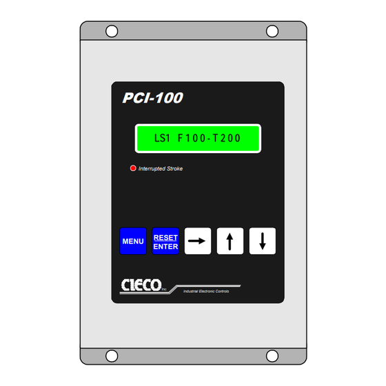
Industrial Electronic Controls The PCI-100LS Programmable Limit Switch receives position and motion feedback from the resolver. The resolver is attatched to the main shaft of the press. The PLS knows when the press is engaged, how fast it is running, the position of the crank shaft, and when the clutch is disengaged. -
Page 4: Keypad
KEYPAD Helpful display codes > When this symbol is displayed the key enables that function to be programmed When this symbol is displayed the key causes the program to select the next function (ENT) When (ENT) is displayed, pressing the ENTER key will perform the function shown. When a blinking cursor is shown, use the arrow keys to change the data and the ENTER key to save the data. -
Page 5: Menus And Functions
MENUS and FUNCTIONS There are 5 menus. Four of them have other functions. 1 POS/TACH shows the current real time position and speed of the press in strokes per minute. There are no additional functions under this menu. 2 INITIAL contains 4 functions. These are only set when the control is initially installed. •... - Page 6 Menus and Functions continued 4 COUNTERS contains 5 counter functions • ^STROKE S000000 keeps a running total of the strokes count. The strokes counter will increment every stroke of the press. It can be used with the batch to stop the press when the required number of parts have been made. •...
-
Page 7: Installation Steps
INSTALLATION STEPS Mount the controller in an area that can be easily viewed by the operator. Install the resolver Install the resolver cable Make all the electrical connections and double check the connections to make sure they are correct Apply power Enable programming by entering the Supervisory Code Zero the resolver at TDC. -
Page 8: High And Low Speed Limits
CHAIN BREAK DELAY The motion delay is used to compensate for starting delays caused by clutch slippage. ^MDLY >D999 1. The motion delay is factory set at 999. Decrease the delay until motion fault occur. 2. Slowly increase the delay until motion faults are eliminated. 3. -
Page 9: Speed Compensation
SPEED COMPENSATION Speed compensation offset angle is the number of degrees of advance per 100 SPM increase in press speed over the programmed starting speed. Example 1: Top Stop 1. Program the speed compensation starting speed S to the slowest operating speed of the press. eg. 50spm 2. -
Page 10: Troubleshooting
TROUBLESHOOTING fault messages MESSAGE MOTION FAULT Resolver shaft speed equals or exceeds the boundaries of the programmed SPM limits while the brake solenoid input is at 115VAC (brake off) A broken resolver to machine shaft coupling or chain. Excessive clutch slippage or the motion delay is set to short. An attempt is made to run the machine with the brake solenoid input disconnected. - Page 11 PLS3 PLS 3 - 4 Option A 8A @ 110VAC NO standard Option B 4A @ 110VAC NO-NC on request PLS4 CIECO Inc LEDs Color Indication Green FAULT/BATCH energized Green Limit Switch 1 energized Green Limit Switch 2 energized Green...
-
Page 12: Resolver Mounting
RESOLVER MOUNTING The resolver shaft and stator should NEVER be rigidly coupled to the machine shaft and stator. Either the shafts or the stators should have a flexible member which will allow freedom of movement in all planes except rotation. (No two shafts ever have equal runout regardless of their precision. Even if individual shaft assemblies have the same "amount"... - Page 13 PCI PANEL CUTOUT 1.65 1.65 1 13/16" 1 13/16" Drill holes 9/64" 2.325 4 places 2 1/8" GREY AREA 4 1/4" x 3 5/8" CUTOUT 4.65 2 1/8" 2.325...
- Page 14 Machine ground is not sufficient. BRAKE SOLENOID INPUT: is used by the PCI-100LS to sense when the clutch is engaged (110VAC) and when the brake is applied (0 VAC). Incorrect wiring of this input will result in nuisance motion faults.
- Page 15 WIRING PCI main terminal RESET ENABLE/DISABLE: Disable - will not allow any fault to be reset. Enable - any fault can be reset from the keypad or the remote reset button. Connections 1 and 3 of the PCI main terminal are to be connected in the Remote Reset Connect input to...
- Page 16 WIRING PCI resolver terminal 7 pin Resolver terminal 1 2 3 4 5 6 7 To terminal 27 of the power supply and resolver cable shield. 1 - R1: BLUE/WHITE STRIPE Reversing S1 and S3 will change 2 - R2: WHITE/BLUE STRIPE the ascending count direction.
- Page 17 4A @ 110VAC NO-NC on request PLS4 CIECO Inc Fault/Batch relay Is energized (closed) during normal operation and will open in a fault or batch condition The fault/batch relay is rated for 8 amps @ 110VAC and is fused for 2.5 amps PLS relays •NO...
Need help?
Do you have a question about the PCI-100LS and is the answer not in the manual?
Questions and answers