Table of Contents
Advertisement
Advertisement
Table of Contents

Related Manuals for Hitbox CT 520

Summary of Contents for Hitbox CT 520
-
Page 2: Table Of Contents
CONTENTS 1. Contents..........................1 2. Safety warning........................2 3. Machine description......................3 4. Technical parameters table....................4 5. Panel function description....................4 6. Installation instruction.......................6 7. Operation introduction......................8 8. Maintenance ........................9 9. Notes before checking......................9 10. Precautions........................10 11. Questions to be run into during Cutting................11 12. -
Page 3: Safety Warning
2.SAFETY WARNING On the process of welding or cutting, there will be possibility of injury, so please take protection into consideration during operation. For more details please review the Operator Safety Guide, which complies with the preventive requirements of the manufacturer. Electric shock——May lead to death !!... -
Page 4: Machine Description
If you fail to fully understand the manual, or fail to solve the problem with the instruction, you should contact the suppliers or the service center for professional help. WARNING! Electric leakage protecting switch should be added when using the machine!!! 3.MACHINE DESCRIPTION The welding machines are rectifiers adopting the most advanced inverter technology, which can apply in plasma cutting system of using pressing air. -
Page 5: Technical Parameters Table
4.TECHNICAL PARAMETERS TABLE Model CT-520DPC Parameters Mode Input voltage(V) Single Phase AC220±15% Frequency (Hz) 50/60 Rate input current ( A) Current Range(A) 10-50 5-200 10-200 No-load voltage(V) Rate output voltage Gas after flow(S) 0-10 0-10 (V)V Remote control Ignition way TOUCH Efficiency(%)... - Page 6 5.2.3 Attenuation parameter adjustment:When completing a section of welding and ending the arc, in order to ensure good forming, the current is required to gradually decrease to stop. This parameter is used to adjust the decay time of the current. Note:When using the "foot pedal"...
-
Page 7: Installation Instruction
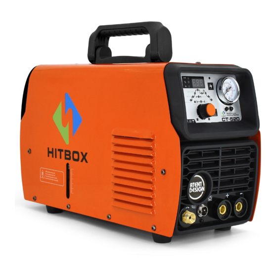
Welding mode selection Function selection Indicator light Adjust knob / parameter button (press the knob light to flash, turn the knob to adjust the indicator to adjust the parameter position, press the knob again, rotate the knob to adjust the parameter when the light is not flashing) Gas check button High frequency button Display... - Page 8 system. 6.2 Connect the protective gas source. The gas supply passage shall include a gas cylinder, an argon gas pressure reducing flowmeter and a gas pipe. The connecting portion of the gas pipe shall be fastened with a hose clamp or other articles to prevent argon gas leakage and air ingress. 6.3 Ground the cables with section area no less than 6mm to the housing, the way is connecting screw in the back of the power source to ground device, or make sure ground terminal of power...
-
Page 9: Operation Introduction
7.OPERATION INTRODUCTION 7.1 Use AC TIG welding function description: 7.1.1 Turn on the power switch and the fan inside the machine starts to rotate. 7.1.2 Press the function button and select the desired function to operate. 7.1.3 Turn on the argon switch and adjust the gas flow to the rated standard (see flow meter). 7.1.4 Adjust the ratio of positive and negative current time according to the degree of oxidation of the surface of the workpiece to be welded. -
Page 10: Maintenance
WARNING: It is strictly forbidden to insert or remove any cable or connector in use during the welding process. This operation will endanger personal safety and cause serious damage to the equipment. 8.MAINTENANCE WARNING: Power must be turned off for all checking and maintenance, before opening the housing, make sure the power plug is disconnected. -
Page 11: Precautions
NOTICE: In the period of guarantee maintenance, if user makes wrong check and repair for malfunction of welding/cutting machines without our permission, the free maintenance guarantee offered will be invalid 10.PRECAUTIONS 10.1 Surroundings 10.1.1 The welding operation should be carried out in a relatively dry environment, and the air humidity should generally not exceed 90%. -
Page 12: Questions To Be Run Into During Cutting
mark. Before use, use a cable with a section larger than 6mm2 to reliably ground the welder's casing to discharge static electricity or prevent accidents due to electric leakage. 10.2.6 If the welder exceeds the standard load continuation rate during operation, the welder may suddenly enter the protection state and stop working. -
Page 13: Troubleshooting And Fault Finding
11.4 The current cannot be kept stable during the use of the welder: This situation may be related to the following factors: 11.4.1 The grid voltage changes. 11.4.2 Serious interference from the power grid or other electrical equipment. 11.5 cutting can not penetrate the steel plate: 11.5.1 Current regulation error. - Page 14 discharge "sa sa sa" sound, no welding output. Abnormal 1. The primary line of the arcing transformer has poor contact with the power board and indicator light is retightened. does not light, no 2. The discharge nozzle is oxidized or the distance is remote. The surface oxide film of high frequency the discharge nozzle is treated or the distance of the discharge nozzle is adjusted to 1 discharge "sa sa...
- Page 15 CT-520 Fault symptom Exclude 1. Confirm that the air switch is intact or closed. The fan does not rotate, the 2. Confirm that the power grid connected to the output cable has power. digital meter has no display, 3. The thermistor (four) on the power supply board is damaged (this is usually caused by DC24V relay failure or poor contact contact).
- Page 16 4. It may be that the feedback circuit is open. Tungsten needle burnt The duty cycle is adjusted too much to reduce the duty cycle. seriously 1. The welding gear selection is incorrect; Can not break the oxide film 2. The duty cycle adjustment is too small; when welding aluminum 3.
-
Page 17: Explosive View
13.EXPLOSIVE VIEW Control PCB Quick connector socket Inverter board 2 clapboard Electromagnetic valve Pressure gauge Electromagnetic valve Wire buckle connector stand Display board Arc ignition coil Power switch Front panel Hinge Rear panel Inverter board 1 Bottom board Down rear plastic panel Upper front plastic Water separator Gas inert...
Need help?
Do you have a question about the CT 520 and is the answer not in the manual?
Questions and answers