
Subscribe to Our Youtube Channel
Summary of Contents for HIPERBARIC 420
- Page 1 HIPERBARIC S.A. C/ Condado de Treviño 6, 09001 BURGOS – SPAIN Tel.: +34 – 947 473 874 info@hiperbaric.com INSTRUCTION MANUAL HIGH PRESSURE PROCESSING - Hiperbaric 420 integrated – www.Hiperbaric.com Nestle...
- Page 2 2. Responsibilities HIPERBARIC, S.A. shall be under no liability in respect of any defect, consequences and damage arising from fair wear and tear, wilful damage, negligence, abnormal working conditions, failure to follow the HIPERBARIC’s instructions (whether oral or in writing), failure to follow the Operations Manual, or alteration or repair of the Goods without the HIPERBARIC’s approval or if the machine securities are manipulated;...
- Page 3 Hiperbaric machine. The user shall keep a stock of spares according to HIPERBARIC, S.A. recommendation. The use of not original Hiperbaric S.A. wear and spare parts or not previously approved by Hiperbaric S.A. will result on the cancellation of the warranty and can create unsafe conditions.
- Page 4 3. Safety System, All Hiperbaric systems are fitted as standard with a PLC for safety integrity level (SIL) 3, as defined in ANSI/ISA 84.00.01-2004 part 1. This safety PLC monitors pressure and alignment, and whenever the machine surpasses a predefined set values it quickly release the pressure eliminating hazardous conditions.
- Page 5 Nestle...
- Page 6 Nestle...
- Page 7 Nestle...
- Page 8 HIPERBARIC S.A. C/ Condado de Treviño 6, 09001 BURGOS – SPAIN Tel.: +34 – 947 473 874 info@hiperbaric.com Hiperbaric HPP machine LOTO sequence LOTO operation for HPP machine maintenance: Intensifier/ high pressure failure detection The high pressure leaks can be detected by the machine operator, observing abnormal pressurization times, alarms, or steam clouds through the plastic windows.
- Page 9 Up to this point the LOTO process is common for any kind of maintenance operation (relief valves, hydraulics, plug seals, high pressure pipes and elements...). To do these operations the whole machine will remain disabled along the fixing. www.Hiperbaric.com Nestle...
- Page 10 At this moment you can open the doors of the machine, note that the safeties in the machine keep down, therefore no movements in the machine will occur. Next step to ensure safety is to take the “safety joystick” used to protect the operator. www.Hiperbaric.com Nestle...
- Page 11 Once it is rearmed you can activate the “vessel pressing button” on the top of the “safety enabling switch” to activate the hydraulic unit in order to press the vessel against the top. Vessel pressing button Safety enabling switch www.Hiperbaric.com Nestle...
- Page 12 Now the intensifier is in safe condition in terms of power supply. Then it is necessary to isolate the intensifier maintenance working area from the pressurized pipes of the opposite side. EMERGENCY ELECTRIC STOP CABINET TS PANEL MAIN SWITCH SWITCH SWITCH Figure 1 - General view of electrical cabinet www.Hiperbaric.com Nestle...
- Page 13 4) 3. The M.O. opens the upper hatch and proceeds to remove the red high pressure pipe that connects the intensifier to the high pressure net www.Hiperbaric.com Nestle...
- Page 14 To do that the stainless steel guard must be removed first to have access Fitting covering High pressure pipe High pressure Figure 3 – Located covering. To isolate the intensifier it is only necessary to remove the pipe from the ‘T’ to the covering. www.Hiperbaric.com Nestle...
- Page 15 TECHNICAL DESCRIPTION Figure 4 – Removing the cover of the fitting. Figure 5 – High pressure pipe removed. Now the pipe is removed and a high pressure plug is installed instead www.Hiperbaric.com Nestle...
- Page 16 Figure 7 -High pressure plug fitted from 3/8’’ to 9/16’’ Safety switch Figure 8 – Stainless steel protection upside down. Then the high pressure circuit from the other side is completely isolated and the repairing tasks can be held over the intensifier. www.Hiperbaric.com Nestle...
- Page 17 On the command panel (HMI) the intensifier to be maintained must be disabled (to avoid alarms and malfunctioning messages), then the automatic production can be restarted without the intensifier that has been stopped. (see instruction manual for more detailed information). www.Hiperbaric.com Nestle...
- Page 18 How to proceed. Control Cabinet Maintenance The electrical cabinets shall be de-energized prior to perform any maintenance operation. 1. The enclosures are interlocked with the main switch so it shall be set to "0FF" prior to open it. www.Hiperbaric.com Nestle...
- Page 19 HIPERBARIC S.A. C/ Condado de Treviño 6, 09001 BURGOS – SPAIN Tel.: +34 – 947 473 874 info@hiperbaric.com INSTRUCTION MANUAL HIGH PRESSURE PROCESSING - HIPERBARIC 420 integrated HIPERBARIC S.A. Tel. +34 947 47 38 74 Polígono Ind. Villalonquéjar Fax +34 947 47 35 31 C/.
-
Page 20: Table Of Contents
3.6.3.3. Cycle options ..................60 3.6.4. Operations ......................64 3.6.4.1. Manual movements .................65 3.6.4.2. Low-pressure water circuit ..............67 3.6.4.3. Feeder movements .................68 3.6.4.4. Output feeder movements ...............69 3.6.4.5. High-pressure water circuit ..............75 3.6.4.6. Intensifiers ....................78 3.6.4.7. Intensifiers: Manual movements ..............82 3.6.5. Cycles ........................83 www.Hiperbaric.com Nestle... - Page 21 4.2.3.3. Flexible hose..................118 4.2.3.4. GRUNDFOSS pump ................118 4.2.3.5. Low pressure filter .................119 4.2.4. High pressure system ..................120 4.2.4.1. Intensifiers ....................120 4.2.4.2. Tubes and connections .................120 4.2.4.3. Discharge valve ..................125 4.2.5. Hydraulic system ....................130 4.2.5.1. Hydraulic unit..................130 4.2.5.2. Accumulator ..................133 www.Hiperbaric.com Nestle...
- Page 22 4.5. Preventive maintenance table ..................155 Chapter 5 Anomalies, their probable cause and possible solutions ..........156 5.1. Table of main faults on the Hiperbaric 420 ...............156 5.2. Table of break downs, their cause and solution on the hydraulic unit......160 5.3.
-
Page 23: Chapter 1 . Introduction
The reaction caused by very high pressures basically involves non covalent links, electrostatic and hydrophobic interactions. This enables the life of the food to be increased without requiring either heat treatments or chemical additives. www.Hiperbaric.com Nestle... -
Page 24: Objective
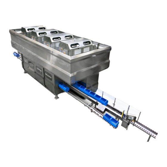
HIGH PRESSURE EQUIPMENT INSTRUCTIONS MANUAL 1.1.3. Objective The aim of this Instruction Manual is to describe how the HPP Machine operates. It has been designed and manufactured by: HIPERBARIC S.A. C/ Condado de Treviño 6 Pol. Industrial Villalonquéjar 09001 Burgos SPAIN LJ MINOR Install'n Nestlé... - Page 25 HIGH PRESSURE EQUIPMENT INSTRUCTIONS MANUAL NOTE: This Layout could not be the real one. Only for information. Figure 1.- General view of the machine www.Hiperbaric.com Nestle...
-
Page 26: Description Of The Elements
The plugs of the pressure chamber have to bear all the working pressure axially. Therefore, they both rest directly on a wedge (2) each, which are also the pieces that transmit the pressure from the chamber to the yoke (4), or steel frame, which must, in the last instance, bear all these www.Hiperbaric.com Nestle... -
Page 27: High Pressure Circuit
Vibrations from the discharge valve during depressurisation are absorbed by the structure for guiding them. Oil circuit High-pressure water circuit Supply water circuit www.Hiperbaric.com Nestle... - Page 28 HIGH PRESSURE EQUIPMENT INSTRUCTIONS MANUAL Figure 3.– High Pressure Circuit www.Hiperbaric.com Nestle...
-
Page 29: Low Pressure Circuit
There is a pneumatic valve system to control the various functions of the estampinox pump (5); these are filling the chamber and emptying the trays. Figure 4 shows a diagram of the low pressure circuit. www.Hiperbaric.com Nestle... - Page 30 Hiperbaric 110650065005 H04-021-30-01017 Carcasa filtro agua inox 520120AN10B1CE H04-021-30-01018 Cartucho malla Supa Gard 10 micras para filtro INOX 420 integ. H04-021-30-03019 Válvula mariposa neumática/ Pneumatic butterfly valve M/M DN-65 Cod.: V4800-110450065M 6-a H04-021-30-02015 Actuador neumatico simple efecto/ Pneumatic actuator Cod.:24310SE H04-021-30-02010 E-válvula / E-valve 1"...
-
Page 31: Hydraulic Unit
This prevents accidents on the moving part of the loading line. In addition, some safety pictograms that show the residual dangers are situated in all the machine. www.Hiperbaric.com Nestle... -
Page 32: Description Of Operation
The machine is designed to protect the operator from risk and danger arising from its normal operation. The operator will work in the work station, or stations, as shown on the plan for these (see working zone plan). These areas have special safeguards, and the button panel must be operated from these. www.Hiperbaric.com Nestle... - Page 33 HIGH PRESSURE EQUIPMENT INSTRUCTIONS MANUAL WORKING AREA PLAN www.Hiperbaric.com Nestle...
- Page 34 HIGH PRESSURE EQUIPMENT INSTRUCTIONS MANUAL WORK ZONE AGV´s WORK ZONE AGV´s Figure 5.- Work Zones www.Hiperbaric.com Nestle...
-
Page 35: Technical Details Of The Equipment
HIGH PRESSURE EQUIPMENT INSTRUCTIONS MANUAL 1.2. Technical details of the equipment 1.2.1. Dimensions The main dimensions for the HPP Machine are shown in the following Figure. Figure 6.- Machine dimensions www.Hiperbaric.com Nestle... -
Page 36: Technical Data
HIGH PRESSURE EQUIPMENT INSTRUCTIONS MANUAL 1.2.2. Technical data Specifications of the Machine Hiperbaric 420i o Serial number: 9712 Specifications of the vessel: Ø . = 380 mm. Ø . = 1000 mm. Length = 4000 mm. Weight = 21.5 Ton. - Page 37 15 l/min (4 gal/min) For Hiperbaric 55, the heat load and flow will be the half, as this model has just a single high pressure pump. For B22 Intensifier, the heat load and flow will be the half, as this model has just a single high pressure pump.
- Page 38 10 ° C are given in the following chart: Power dissipated by each Power dissipated by the double high pressure pump machine kW (HP) kW (HP) Hiperbaric 55 9 kW (12 HP) Hiperbaric 120, 135, 300, 420 10 kW (13 HP) 3 kW (4 HP) www.Hiperbaric.com Nestle...
-
Page 39: Foundation
HIGH PRESSURE EQUIPMENT INSTRUCTIONS MANUAL 1.2.3. Foundation The Hiperbaric 420i machine shall have the following foundation: Figure 7.- Foundation www.Hiperbaric.com Nestle... -
Page 40: Intensifiers Inlet Water Quality
Water properties out of these ranges could decrease the high pressure components life of the machine. 1.2.5. Inlet water pressures The minimum pressure requirement for feeding the tanks of the Hiperbaric 420i machine is 3 bar. This pressure should not be higher than 6 bar. - Page 41 Measurement uncertainty The estimated values for the sound level meter uncertainty are the following: For weighted values (L For peak values (L C PEAK www.Hiperbaric.com Nestle...
-
Page 42: Chapter 2 Commissioning
This symbol warns that there are hot surfaces which could cause burns. High pressure! This symbol warns of danger from high pressures. Take care! This symbol warns of operations that could damage the machine. Special instructions on the economical use of the machine www.Hiperbaric.com Nestle... -
Page 43: Transport, Handling And Housing
Do not make any sudden movements during the handling of the machine and prevent it from being hit by blunt objects. HIPERBARIC, S.A. will not be held responsible for material or personal damage caused by not following the instructions as explained in this document. -
Page 44: Handling Instructions
1- Mount the lugs onto the hooks on the crane. Two cranes, or one with enough load capacity, must be used to handle the Hiperbaric 420i machine (48.5 t approximately, the machine without the vessel and supports), (71 t the total machine without intensifiers and load and unload conveyors, approximately). - Page 45 Fasten these in such a way that they cannot move while the machine is being handled. They shall be situated in the pressure position to avoid their movement during the handling of the machine. Figure 10.– Fastening the plugs and wedges A crane with sufficient load capacity must be used to handle the machine. www.Hiperbaric.com Nestle...
- Page 46 2. Once these are in place, place the chamber carefully onto some pieces of wood. Figure 12.– Fastening the high pressure chamber A crane with sufficient load capacity must be used to handle the machine. Unloading the machine The machine weight is roughly the following: www.Hiperbaric.com Nestle...
- Page 47 Total machine (without intensifiers): 71 Tm Intensifier: 2.2 Tm each of them (without oil) (DMB6i) + 400Kg of oil - Standard Hiperbaric 420 has 4 DMB6i intensifiers: 8.8 Tons Mezzanine + covering (without intensifiers)= 7.45 Tons. Total weight (including all components): 88 Tons A crane with sufficient loading capacity is required.
- Page 48 HIGH PRESSURE EQUIPMENT INSTRUCTIONS MANUAL Some pictures illustrate this procedure. IPN Shape Carrier Figure 14.- Movement of the machine 2 To do the turns of the machine a turning carrier shall be used. Figure 15.- Movement of the machine 3 www.Hiperbaric.com Nestle...
-
Page 49: Commissioning The Unit
2. Put the chamber in line with the plugs: 2.a. The horizontal alignment must be carried out in accordance with the labels on either end of the hydraulic cylinders that move the support on the bed. www.Hiperbaric.com Nestle... - Page 50 2.b. The vertical alignment must be carried out by varying the height of the plugs where they connect to the beam adjoining the slides on the guides. (This operation has to be done by qualified staff). Some spacers are introduced here to level the plug www.Hiperbaric.com Nestle...
-
Page 51: Starting Up The System
2. Check that there are no leaks from the hydraulic lines on the unit. 3. Check that there are no water leaks on either the high pressure circuit or the low pressure circuit. 4. Check that the vessel and plugs are aligned correctly. www.Hiperbaric.com Nestle... - Page 52 The unit must not be installed in places where the temperature may drop to below 3ºC or reach over 40ºC. If these limits are not met, Hiperbaric, S.A. shall be contacted for clarification. The intensifiers and the electrical panel must not be installed in damp areas.
-
Page 53: Chapter 3 Operation
Chapter 3 Operation 3.1. Introduction For correct operation of the Hiperbaric machine during normal production operations, introduction, display and advanced operation, the different functions built into the machine’s keypad have to be used. The keypad consists basically of a touchscreen, buttons, switches and emergency stop. -
Page 54: Description Of The Control Devices
If we push the button, we reset the protection, provided that there is no alarm activated. 4.- Emergency button: This emergency button changes the machine to error status, with the result that the machine discharges pressure. www.Hiperbaric.com Nestle... -
Page 55: Elements On The Button Panel
9.- Adjustment mode reset button (red button): Once you have attained all the necessary conditions to achieve the adjustment mode, you just have to press this button to reset the machine in adjustment mode. www.Hiperbaric.com Nestle... -
Page 56: Operation Modes
When a user with sufficient permission is logged in you have to select on the screen the request to go into maintenance mode. To do this, press “System Setup” on the home screen. www.Hiperbaric.com Nestle... - Page 57 Figure 21.- System set up screen In the “Mode Setup Configuration” screen you have all possible special configurations of the machine and here you must select the chosen mode, in this case the Adjustment Mode button. Figure 22.- “Mode Setup configuration” screen www.Hiperbaric.com Nestle...
- Page 58 “alignment rearm button” located inside the fairing. This will reset the machine in alignment mode. You will know that the machine is in alignment mode because the yellow beacon that was continuously lit, will flash at 1 second intervals. www.Hiperbaric.com Nestle...
-
Page 59: Status Bar
This item is present in all the screens that make up the programming of the touchscreen, occupying the space at the top of the screen. In this area of the screen the most representative data of the Hiperbaric machine operation are collected, which we will now explain. - Page 60 As shown in the following area, the current pressure of the Hiperbaric and the time of hyperbaric processing are recorded. The status bar also displays the date and time.
-
Page 61: Users
Passwords: main1, main2, main3 Quality: Users : qual1, qual2, qual3 Passwords: qual1, qual2, qual3 Engineering: Users : engi1, engi2, engi3 Passwords: engi1, engi2, engi3 If you try to access any screen without sufficient privileges the following message is displayed: www.Hiperbaric.com Nestle... -
Page 62: Screens
System configuration: On this screen you can change various machine parameters such as language, units, time, etc., configure the plugs and other functions that will be shown later. Alarms and warnings: From here you can view active warnings, active alarms and alarm history. www.Hiperbaric.com Nestle... -
Page 63: Latest Alarms And Warnings Currently Activated
Press in the info icon a pop up panel will show you the state of the main variables of the machine before the first alarm was generated. www.Hiperbaric.com Nestle... -
Page 64: Warnings & Alarms Log
Warnings of the machine are organized by groups according to the affected element. Nomenclature is shown below: G0: Warning Machine. G1: Warning Intensifiers Group 1(HPPump1) G2: Warning Intensifiers Group 2 (HPPump2) G3: Warning Intensifiers Group 3 (HPPump3) G4: Warning Intensifiers Group 4 (HPPump4) G20: Warning Input Manipulation. G21: Warning Output Manipulation. www.Hiperbaric.com Nestle... - Page 65 Absolute measure LVDT2 under pressure, out of range AV0167G00 Relative measure LVDT1 under pressure, out of range AV0168G00 Relative measure LVDT2 under pressure, out of range AV0169G00 Differential measure LVDT1-2, out of range AV0183G00 Plug 1. Back and Filling positions detected simultaneously(P1-P2) www.Hiperbaric.com Nestle...
- Page 66 Unable to open Plug 2 without the Wedge 2 well positioned AV0220G00 Unable to close Plug 1 without the vessel positioned inside AV0221G00 Unable to close Plug 2 without the vessel positioned inside AV0222G00 Unable to activate main tank fill valve, max level detected www.Hiperbaric.com Nestle...
- Page 67 Light curtain crossed in the load zone AV0003G20 Stopper must be in back position to move the Feeder AV0004G20 There is a container in the unloading belt AV0019G20 AVxxxG21 Manipulation Output Group AV0001G21 Light curtain crossed in the Unload zone www.Hiperbaric.com Nestle...
-
Page 68: List Of Alarms
Adjust Mode Beacon broken or in short-circuit AL0021G00 Elongation Difference with factory value less than 0. AL0022G00 Exceeded maximum and minimum elongation value factory AL0023G00 Current Pressure differential greater than permitted maximum pressure difference AL0024G00 Pressure measurement error. Machine opened with pressure(transducer 1) www.Hiperbaric.com Nestle... - Page 69 AL0107G00 Too much time placing Plug 2 to filling position AL0108G00 Too short time placing Plug 2 to filling position AL0109G00 Too much time closing Plug 1 (closing machine) AL0110G00 Too short time closing Plug 1 (closing machine) www.Hiperbaric.com Nestle...
- Page 70 Tried to close Wedge 2 with Plug 2 out of safety position AL0149G00 Tried to introduce Vessel with Plug 1 out of safety position(inductive sensor) AL0150G00 Tried to introduce Vessel with Plug 2 out of safety position(inductive sensor) www.Hiperbaric.com Nestle...
- Page 71 Plug 1. Filling and Pressure positions detected simultaneously(P2-P4) AL0188G00 Plug 1. Plug inside the vessel and Pressure positions detected simultaneously(P3-P4) AL0189G00 Plug 2. Back and Filling positions detected simultaneously(P1-P2) AL0190G00 Plug 2. Back and Plug inside the vessel positions detected simultaneously(P1-P3) www.Hiperbaric.com Nestle...
- Page 72 Sensors side 1 &2 HP1 detected simultaneously AL0004Gxx Sensors side 1 &2 HP2 detected simultaneously AL0005Gxx Too much time moving to side 1 HP1 AL0006Gxx Too much time moving to side 1 HP2 AL0007Gxx Too much time moving to side 2 HP1 www.Hiperbaric.com Nestle...
- Page 73 Time too short moving the Feeder ahead AL0013G20 Too much time moving the Feeder to the back position. Changing speed AL0014G20 Time too short moving the Feeder to the back position. Changing speed AL0015G20 Too much time moving the Feeder to the back position. www.Hiperbaric.com Nestle...
- Page 74 Unloading Belt Safety Door opened AL0008G26 No safety. E-Stop Control Panel pressed or Door Opened AL0009G26 No Safety Light Curtains AL0010G26 Unloading Belt thermo-protector tripped AL0011G26 Blower thermo-protector tripped AL0012G26 Transfer Unloading Belt thermo-protector tripped AL0013G26 No communication between PLC's www.Hiperbaric.com Nestle...
-
Page 75: Beginning Inputs
In order to choose local cycles , in the screen system setup the check box “Remote Data” don’t have to be marked. If also check box “Enable Canister code” is selected the user will can introduce the codes of the canister and save in the data base. www.Hiperbaric.com Nestle... - Page 76 The screen is displayed by default only the first four, to display all the products click on the "+" icon shown with a yellow circle in the image. Figure 30.- Screen displaying all the products www.Hiperbaric.com Nestle...
- Page 77 Figure 32.- Product by canister This screen is very similar to the above, the basic difference being the upper right of the screen in which, depending on the container that is active in the entered data, the data in the www.Hiperbaric.com Nestle...
-
Page 78: Remote Data Cycle
Figure 33.- Process with remote cycle data Other production screen tools 3.6.3.3. Cycle options Choose between continuous and discontinuous cycle using the following selector. www.Hiperbaric.com Nestle... - Page 79 There is another selector from which we can choose other settings. This selector is: The options we have are as follows: No Feeder: By setting the selector to No Feeder, the machine will perform cycles without using the Feeder and without performing the movement thereof. www.Hiperbaric.com Nestle...
- Page 80 "Production Order" or "Manual Controls (Feeder)" screens or by clicking on the lock symbol showed at the top left visible in each of the screens. Clicking on any of these items an informational message indicating the risks to unlock will appear. Figure 34.- Feeder blocked www.Hiperbaric.com Nestle...
- Page 81 This screen shows two graphs, one is the state of the pressure, and the other is the temperature, and both show the time. The length of each cycle can be seen, with its pressure rise, hyperbaric processing length, in addition to the discharge of the cycle. www.Hiperbaric.com Nestle...
-
Page 82: Operations
When the “Rearmament” button is pressed, the machine starts the sequence for the stage it has reached. In order to protect the machine, the cycle cannot continue under automatic mode if manual hydraulic movements have been done. www.Hiperbaric.com Nestle... -
Page 83: Manual Movements
100 bar if the user has the level of operator and may be up to 180 bar if the user has maintenance level. This screen, apart from performing the manual movements of the machine, displays other very useful information and actions for the equipment's daily use. www.Hiperbaric.com Nestle... - Page 84 Note: in order to run the hydraulic unit manually from this panel, unless one of the intensifiers has to be selected in “Service machine” mode be enabled to give oil service to the machine. www.Hiperbaric.com Nestle...
-
Page 85: Low-Pressure Water Circuit
"Plugs settings." We can directly access the plugs settings screen from this screen by simply clicking on the appropriate button . The usefulness of this page is explained in section 3.5.8.1 of this manual. 3.6.4.2. Low-pressure water circuit Figure 40.- Low-pressure water circuit screen www.Hiperbaric.com Nestle... -
Page 86: Feeder Movements
There are also a number of sensors that indicate the position each drive element of the machine. Mode and status of the unload manipulation is also showed in the box “Unload Zone Information”. www.Hiperbaric.com Nestle... -
Page 87: Output Feeder Movements
HIGH PRESSURE EQUIPMENT INSTRUCTIONS MANUAL Figure 41.- Input feeder movements 3.6.4.4. Output feeder movements This is the main page of the output handler. Here we can choose the various options pages in the output handler. www.Hiperbaric.com Nestle... - Page 88 The unloading transfer has four possible movements, which in manual mode will be driven by the four arrows on the display. Figure 43.- Output feeder movements To make a movement, it is necessary that no adjacent elements interfere with the course of the movement. www.Hiperbaric.com Nestle...
- Page 89 Figure 44.- Alarm history screen Clicking on the warning history button from this screen will allow us to access the warning history screen. Figure 45.- Warning history screen www.Hiperbaric.com Nestle...
- Page 90 (vessel) and which will arrive to the unload belt once the feeder introduce new carriers in the vessel. "True reading of Containers." At the end of the discharge line there is a container code reader which reads the true value of each container number in order to www.Hiperbaric.com Nestle...
- Page 91 Apart from the screens accessed from the home screen, there is a series of screens which can be accessed from any screen shown above, since we may need to access any of these at any given time. "Main." We can access the Main screen from any other screen of the set. www.Hiperbaric.com Nestle...
- Page 92 We can access the "Canister Map" screen mentioned previously. "Alarms." From here we can access the Active Alarms screen in order to easily diagnose any problem the machine may have. The screen is as follows. Figure 49.- Active alarms and alert screen www.Hiperbaric.com Nestle...
-
Page 93: High-Pressure Water Circuit
Firstly, one of the most important elements is the value of the current transducer pressure located on the corresponding side. The yellow indicators indicate whether the discharge valves are open or closed, if the indicator lights are at the bottom, www.Hiperbaric.com Nestle... - Page 94 We will not expand further on the operation of the LVDT, as it is explained in the manual movements chapter. However, in this screen there are rules that are highlighted according to the LVDT measurements. Figure 53.- Vessel position control www.Hiperbaric.com Nestle...
- Page 95 Figure 55.- Displacement report table Before opening the pressure discharge valve, ensure that there is nobody in the discharge area and that the tanks are properly mounted. www.Hiperbaric.com Nestle...
-
Page 96: Intensifiers
It can also disable the water maintenance of the intensifiers. By default all are enabled but if necessary this disabling is permitted. Figure 56.- Selection High Pressure Pumps www.Hiperbaric.com Nestle... - Page 97 Enable the pump to operate. Select the operating mode, which will be active after pressing “confirm”. Start-up the hydraulic unit. Handle the valves Set the desired oil pressure Move the plunger in the desired direction. www.Hiperbaric.com Nestle...
- Page 98 In the following image there are two distinct areas: one green, where you enter the pressure at which the hydraulic pump has to generate to perform manual movements, and one blue, which indicates the current pressure. Figure 63.- Pressure reading and input. www.Hiperbaric.com Nestle...
- Page 99 Figure 68.- Status of oil return filter. You can also view the oil level status since when it is above the minimum level the tank is represented in grey, but if it is below minimum the colour is red, as seen below. www.Hiperbaric.com Nestle...
-
Page 100: Intensifiers: Manual Movements
“Manual”, the intensifier will remain off (valid for maintenance operations). Figure 71.- Detail of the plunger movement buttons and position detectors. In order to move the plunger manually, use the arrow-shaped buttons indicating the direction of plunger movement as shown in the above figure. www.Hiperbaric.com Nestle... -
Page 101: Cycles
Here you can access the control of the counters of the high pressure chamber. 3.6.6.1. Location and functions of counters On these screen you can carry out the management of the main maintenance data and times of the machine. www.Hiperbaric.com Nestle... - Page 102 Figure 74.- General data button For proper maintenance it is important to reset the counters whenever a change is made to one of the elements included here. Figure 75.- Main Maintenance Screen www.Hiperbaric.com Nestle...
- Page 103 Figure 77.- Intensifier data screen Do not place counters at zero if no parts are changed. Displayed onscreen when "Cycle Times" is clicked on Figure 78.- Cycle times button A screen appears indicating the time each step defined in the cycle takes. www.Hiperbaric.com Nestle...
-
Page 104: System Configuration
In this screen also you can see PLC Version, and the date in Universal Time (UTC) and Local Time Format. Changing the parameters of these screens may alter the outcome of the cycles. Only authorized staff with full knowledge of the machine should make changes to these controls. Figure 80.- System configuration screen www.Hiperbaric.com Nestle... -
Page 105: System User Setup
When it is changed any value, you should click to the Apply button to save them. Also you can introduce any comment regarding with the change. If Apply is no pressed, upon exiting the screen, a message will appear asking if we wish to keep the changes or reject them. www.Hiperbaric.com Nestle... -
Page 106: Backup Setup
For more information about that, view point 3.3 Operation Modes. The screen displayed when you click on the button is the following: www.Hiperbaric.com Nestle... -
Page 107: System Times
Figure 83.- Mode configuration screen 3.6.7.4. System times The “system times” button can change certain critical values for the operation of the machine which it may be necessary to change for the proper operation thereof. Figure 84.- System times. www.Hiperbaric.com Nestle... -
Page 108: Plug Setup
To access the screen in question you must have sufficient user permissions. This menu should only be accessed after contacting HIPERBARIC S.A. Any error at this point could cause serious damage to the machine. Therefore, only qualified and authorized staff may use these functions. -
Page 109: Device Monitor
Clicking on the "Device Monitor" button will allow us to access a screen to monitor the status of the machine screens. It displays all information of interest to verify the proper operation of the element. Figure 87.- Monitor status www.Hiperbaric.com Nestle... -
Page 110: Panel Configuration
As we can see in the following image, there are 5 areas in which the containers can be found. Load transfer, infeed belt, vessel, outfeed belt and unload transfer. This is very useful in knowing the location of each container at all times. Figure 89.- Containers map www.Hiperbaric.com Nestle... - Page 111 AGV. This indicator is the next , and if we click on it, the help screen appears in which all conditions that are needed for the load transfer to be in the desired state are indicated. www.Hiperbaric.com Nestle...
-
Page 112: Recipes
Holding time: This is the time for which the setpoint pressure will be maintained once reached. After this time has elapsed the chamber is depressurized. www.Hiperbaric.com Nestle... -
Page 113: Creation Of A Recipe
It is Advisable to check the recipe created data to rule out any errors when starting new cycles with the recipe concerned. The recipe will not be used until it is saved. www.Hiperbaric.com Nestle... -
Page 114: Invalid Recipe
In order to show you which is the problem, the next message will be display in the touch screen. If you press the In the purple circle you will be directed to the carrier map display as to read the alarm message. The message will show as below: www.Hiperbaric.com Nestle... -
Page 115: Technical Support
By clicking on this icon you can access to technical support panel where you can find all the ways to contact with the Hiperbaric service aftersales, also there is a chat where you can talk with one of our technicians. - Page 116 The Door that covers each intensifier in each high pressure pump.The pipe settled covering that covers the high Pipe settled Ghp12, Ghp34, Ghp56, Ghp78. pressure Tee when performing maintenance in the intensifier (see LOTO Procedure for more information). www.Hiperbaric.com Nestle...
-
Page 117: Alignment System
The last thing required to finally achieve alignment mode is to press the “alignment rearm button” located inside the machine next to the emergency stop. At this point, the machine will reset itself in alignment mode. Alignment rearm button Figure 99.-Alignment rearm button www.Hiperbaric.com Nestle... - Page 118 To adjust each sensor we have to set the absolute measure as close to 0 as possible (between +/- 0.05mm, see red circle on the image above). This is done acting on the control alignment regulation nut shown on the image below. www.Hiperbaric.com Nestle...
-
Page 119: Yoke Elongation Checking And Adjustment Mode
Having met all the conditions it will be necessary to reset the adjustment mode by pressing a button located on the right hand side of the control panel. www.Hiperbaric.com Nestle... -
Page 120: Working With The Machine Without Scada Connection
To do this, every time a cycle ends, the confirmation screen will appear in which operators should record the values shown there in order to maintain traceability and to confirm the cycle. Figure 104.-Cycle confirmation OK screen www.Hiperbaric.com Nestle... -
Page 121: Chapter 4 Maintenance And Cleaning
4.1.2. Abnormal use The Hiperbaric 420i machine must not be used for other types of work not specified by HIPERBARIC, S.A. All the Hiperbaric machines have been designed with a gap between the lower part of the cover and the ground which eases the cleaning of the unit. -
Page 122: Reconstruction / Modifications
4.1.4. Reconstruction / modifications No modifications, extras and rebuilding relating to the safety of the machine should be carried out without consent from HIPERBARIC, S.A. Also no change of placement of the machine shall be done without the explicit consent of HIPERBARIC, S.A. -
Page 123: Maintenance / Repairs /Adjustment /Cleaning
- Lights and audible alarms. - Safety pictograms Control system: The software has been designed to prevent unsafe or undesired modes of operation. The user shall not make any modification of the software without consent from HIPERBARIC, S.A. Any modification could affect safety. www.Hiperbaric.com... -
Page 124: Electrical Energy
Examine / check the electrical equipment on the Hiperbaric machine regularly. Remove any faults such as loose connections or faulty cables immediately. 4.1.13. Hydraulic system Work on the hydraulic systems should only be carried out by staff with specific knowledge and experience of hydraulic systems. -
Page 125: Precautions
NEVER put or leave tools, loose pieces, cloths, etc. inside or on the machine. Personnel maintaining the Hiperbaric machine should always wear eye protection. Not doing this could result in a serious injury. -
Page 126: Maintenance Of The Equipment
It is compulsory to follow these instructions. If this is not the case, HIPERBARIC, S.A. will not be held responsible for any damage to persons and/or materials that may arise. It is essential to read the basic instructions on safety before carrying out any maintenance or cleaning work. -
Page 127: Maintenance Procedure Of The High Pressure System
It is mandatory to follow these instructions, in opposite case the company HIPERBARIC, S.A. will not be held responsible for the consequences and damage to persons and/or materials that could happen. -
Page 128: Consequences And Risks Of Not Doing This Maintenance
(and close to it) and in no case the access will be permitted to anyone not authorized. It is prohibited to introduce parts of the body within the covering of the Hiperbaric machine! It is prohibited the exposure of parts of the human body in the covering openings for the load and unload lines when the machine is under pressure! For the high pressure leaks detection, gloves shall be used!. - Page 129 If there is a leak in this area, the leak could be in the gland and collar connection with the piece 4 (dismount piece 4 and check connection). The reason could be also the pipe inside the plug Figure 106.- Heating zone of the plug www.Hiperbaric.com Nestle...
- Page 130 See the correspondent chapter of the instruction manual to perform this maintenance. Under no circumstances the covering of the machine will be removed when the Hiperbaric machine is under pressure!. It is prohibited the exposure of parts of the human body in the covering openings for...
- Page 131 Under no circumstances the covering of the machine will be removed when the Hiperbaric machine is under pressure!. NOTE: Once detected that the leak is located in that area, it will have to act according to the general maintenance procedure.
- Page 132 Select the operation mode of the intensifiers (manual, automatic) on the operator panel of the facility. For plunger movements, see the HPP machine touch screen program. Manual mode needs to be selected for maintenance of the intensifier units. Remove the high pressure pipe from the unable intensifier. www.Hiperbaric.com Nestle...
- Page 133 HIGH PRESSURE EQUIPMENT INSTRUCTIONS MANUAL Figure 109.- High pressure pump The plug has to be assembled inside the fitting which is placed inside the enclosure. Figure 110.– High pressure pipe removed. www.Hiperbaric.com Nestle...
- Page 134 Do not forget to assemble the high pressure pipe after the maintenance operations, remove the TE plug and place the pipe, the fitting protection must be fastened in its position before starting up the intensifier. www.Hiperbaric.com Nestle...
-
Page 135: Low Pressure Pumping Systems
Keep the machine in a clean working environment, free from dust and grease. Do not install the machine in a corrosive atmosphere. Make sure that the water is clean at all times and change it when it becomes dirty. www.Hiperbaric.com Nestle... -
Page 136: Flexible Hose
1 filter to remove any impurities which would damage the intensifiers. The operation manual in which the maintenance of the pump is described is also included. www.Hiperbaric.com Nestle... -
Page 137: Low Pressure Filter
Depressurise the lines. Dismount the filter by unscrewing. Clean the filter using compressed air. Screw the filter again does not forgetting to put the o-ring. Filter Figure 113.- Low pressure filter Clean with compressed air Figure 114.- Low pressure filter_2 www.Hiperbaric.com Nestle... -
Page 138: High Pressure System
In the following figure can be seen a HP tube connexion. It consists on a gland that is screwed to the fitting and a collar that transmit the force generated by the pressure in the tube to the gland which finally supports the force. Collar Gland Tube Figure 115.- HP tube connexion www.Hiperbaric.com Nestle... - Page 139 If the ‘d’ distance is very small, the pipe will not seal against the seat because the collar will touch it, so a leak will appear. If the ‘d’ distance is very big, the gland will not thread totally so a break of this part could be possible. www.Hiperbaric.com Nestle...
- Page 140 If the diameter at the tubing end is too small use a file to enlarge it. Deburr the cone with emery paper and the inside of the tube with a deburring tool. (see table of tube dimensions) www.Hiperbaric.com Nestle...
- Page 141 The tooling to prepare tubes for mounting is as follows: Threading Coning Figure 119.- Tooling. The tube and gland-collar system shall be mounted in a proper way: Slide the gland nut on the tubing end. www.Hiperbaric.com Nestle...
- Page 142 The different threads used in the HP connections are summarized in the following table: 9/16” Tube 3/8” Tube 1 1/8”-12 UNF 5/8”-18 UNF Gland 9/16”-18 UNF 3/8”-24 UNF Collar 169.5 142.8 Required gland torque (N.m) The Hiperbaric 420i machine HP circuit can be seen in the figure 3. www.Hiperbaric.com Nestle...
-
Page 143: Discharge Valve
If there are water leaks, check the stem and the exchangeable seating for cracks. If cracking is observed, replace the damaged parts with spare parts approved by the HIPERBARIC, S.A. In any case the valves have a temperature transducer to check if there is any leak 4.2.4.3.4. - Page 144 Jet cutting effect Figure 121.- Problem cause of not enough tighten in the stud bolts. If when trying to remove the replaceable seat is locked, push with the hydraulic actuator to remove it when the seat has been retired. www.Hiperbaric.com Nestle...
- Page 145 To make this grinding the following drawing shall be used: H02-100-64-0090E The end of the stem shall be ground as indicated below: In all the surfaces except any indication Figure 123.- Closing stem ground. www.Hiperbaric.com Nestle...
- Page 146 Look for possible defects. Review the stem. 8. Introduce a new replaceable seat. 9. Move the valve back and lift it to introduce the seat (4) which is still connected to the tube and tight the bolts. www.Hiperbaric.com Nestle...
- Page 147 Next, all the bushings and seals can be extracted. NOTE: The part 19 has to not be strongly tightened, only it is necessary make a soft tightening with a wrench and after that, block it with a pin (20) www.Hiperbaric.com Nestle...
-
Page 148: Hydraulic Unit
A complete oil change is recommended! The performance and output of Hiperbaric HPP units and intensifiers depend for a great deal on the hydraulic fluid. The use of premium quality mineral-oil based hydraulic oils such as HLP oils (additives for high pressure) pursuant to the DIN 51 524 standard, chapter 2 is recommended. - Page 149 FDA requirements (a US Agency for Food and Drug Control) for applications in which an incidental contact with a food product is possible. Its properties are excellent: Rust proof Excellent behaviour in extreme temperatures www.Hiperbaric.com Nestle...
- Page 150 -Hydraulic Oil AW 46 (HLP 46) by TEXACO (http://www.texaco.com/) -Hydrex AW 46 (HLP 46) de PETRO-CANADA (http://www.petro-canada.ca) Room temperature <10ºC -Renolin B 520 (HLP 46) by FUCHS (consult Hiperbaric) -Tellus T 46 (HLP 46) by SHELL (http://www.shell.com/) -Mobil DTE 25 (HLP 46) by ESSO (www.mobil.com) -Rando HDZ 46 (HLP) by TEXACO (http://www.texaco.com/)
-
Page 151: Accumulator
These control the movements of the various movable elements on the machine. 4.2.5.4.2. Service During servicing, a visual check must be made to detect any leaks in the water-tight seals on the rods. 4.2.5.4.3. Inspection A visual inspection must be made every 3 months to detect any leaks. www.Hiperbaric.com Nestle... - Page 152 Before re-assembling these in the work position, first check that the unit is air-tight. IMP: carry out a visual inspection of the plunger heads (where the thread is located) of the vessel and plugs actuators every 1 month to see if it is correctly tightened and/or if the thread is damaged. www.Hiperbaric.com Nestle...
-
Page 153: Mechanical System
Make a visual check for any scraping in the vessel every week. If any are found, look for the cause and contact HIPERBARIC, S.A. to tell them of this. To make the visual check, firstly clean the entrance of the vessel with a cleaning agent and then inspect the vessel. - Page 154 In any case HIPERBARIC, S.A. shall be contacted firstly for clarification because this operation is very dangerous for the vessel life. Do not polish the vessel deeper than 80mm (Hiperbaric 300 / 150 / 135) from the end of the vessel, here starts the sealing area. HIPERBARIC, S.A. must be contacted for clarification.
-
Page 155: Vessel Supports
If any are found, look for the cause of these on the plug. Remove the causes of the scratches on the crowns, which may be metal particles on the plug, as these can scratch the air- tight seal and the extrusion proof bush. www.Hiperbaric.com Nestle... -
Page 156: Plug
They must be replaced when they do not retain the pressure and there is leakage on the system. A seal scratched is damaged. Closing ring (H02-420-21-1251C v2 and H02-420-21-1254C v1) If the closing ring is broken the system will not be able to contain the pressure. Change the closing ring in this case. - Page 157 HIPERBARIC, S.A. Front part of the plug (H02-420-21-1162C v1) If the reason of the leak is located in the front part of the plug cause of a crack, HIPERBARIC, S.A. shall be advised to proceed to its replace.
- Page 158 Front part of the plug Figure 125.- Plug. Figure 126.- Plug detail 4.2.6.4.3. Repair High pressure seals (H02-420-21-1095C) To replace the high pressure seal is necessary to unscrew the bolts of the plate (1) and remove the activating plate and the guide. www.Hiperbaric.com...
- Page 159 Leak from position 1: If there is a leak in this area, the leak could be due to: the “gland – collar” connection of the high pressure pipe with the part 4 (dismount piece 4 and check connection) is damaged. There is a crack in the high pressure pipe inside the plug. www.Hiperbaric.com Nestle...
- Page 160 51524. For operating temperatures between 0ºC and +70ºC viscosity should be between ISO-VG 32 and ISO-VG 68. For use at low temperatures, oils of standards ISO-VG 10 or ISO-VG 22 should be used. Sliding bearings It is strongly recommended to substitute the sliding bearings by new ones after 50000 cycles. www.Hiperbaric.com Nestle...
-
Page 161: Wedges
Wedge guides Visual check for scratches on the guides and the wheels. Visually check the welding of the wedges for scratches. If any crack is detected, contact with HIPERBARIC, S.A. 4.2.6.6. Loading and unloading conveyor 4.2.6.6.1. Service If any of the containers is observed to move badly along the loading and unloading conveyors, check the bearings in the wheels. -
Page 162: Alignment Of The Machine
HIGH PRESSURE EQUIPMENT INSTRUCTIONS MANUAL 4.2.6.8. Alignment of the machine As a part of manufacturing process at Hiperbaric, S.A., the pressure vessel has been correctly aligned with the yoke and plugs. In order to maintain under control the alignment the machine has 2 sensors that are continuously checking it. -
Page 163: Bolts Recommended Torque And Mounting Instructions
It is very important to pay attention to this matter regularly to avoid relevant misbehavior from the assemblies involved. The general instructions that have to be followed when mounting bolts in the Hiperbaric machine are the following: SS bolt - female SS thread: A bronze based thread lubricant has to be applied before tighten them. - Page 164 They have to be tightened only 60Nm. The blocking system has to be mounted to avoid the loosing of the bolt. (If there is blocking system) Bronze based thread lubricant has to be used. Hiperbaric 300 / Hiperbaric 135 Plug H04-015-10-01125 Tornillo DIN 912 M16x200 12.9 UNBRAKO Two possibilities: Required torque: 325 N.m.
- Page 165 They have to be tightened only 60Nm. The blocking system has to be mounted to avoid the loosing of the bolt. Bronze based thread lubricant has to be used. If they are broken they have to be substituted immediately because higher damage can be produced to the machine. www.Hiperbaric.com Nestle...
-
Page 166: Cleaning The Unit
Dismounting of the closing ring in order to dry it, is strongly recommended. Note: CIP: Clean in place COP: Clean out of place 4.3.1.1. Cleaning agents The following cleaning agents could be used to clean the Hiperbaric machine; the general instructions have to be fulfilled: www.Hiperbaric.com Nestle... -
Page 167: Package Rupture
This operation should be performed daily or whenever you see necessary. Whatever, it is recommended not to leave the container on the ground to prevent them from getting dirty as the fatigue life of the vessel could be affected. www.Hiperbaric.com Nestle... -
Page 168: Drain Cleaning (Daily)
4.3.2.12. High pressure vessel (Weekly) The high pressure vessel has to be cleaned internally 1. Use 5 minutes cleaning flush cycle of the Hiperbaric machine after the water tanks have been cleaned. 2. Use the alkaline cleaning agent in the vessel adding it to the water tank (Concentration of 0.5%). -
Page 169: High Pressure Plugs And Seals (Weekly)
0.7% in the cleaning agent and the 0.2% in the sanitizer. An ATP testing equipment could be used. 2. Water sampling. The water could be analyzed to control its quality. Frequency will depend on results. The proper water change frequency will depend on results. www.Hiperbaric.com Nestle... -
Page 170: Recommended Checking Method
In each Hiperbaric 420i machine there are located the following systems to measure the pressure: 2 pressure transducers. The measures of these systems are compared to know if one of them is failing. If one of these devices measure 5% more than the permitted assumed measurement (maximum operating pressure), pressure is released and an alarm appears in the screen. -
Page 171: Calibration
Consequently the life of recalibrated H.P. transmitters could be lower than a new one so HIPERBARIC S.A. cannot assume any guaranty in the recalibrated H.P. transmitters and recommends the installation of a new one. - Page 172 HIGH PRESSURE EQUIPMENT INSTRUCTIONS MANUAL www.Hiperbaric.com Nestle...
-
Page 173: Preventive Maintenance Table
4.5. Preventive maintenance table In the following table the preventive maintenance operations are summarized. Also are shown some others operations that are convenient for a good conservation and a correct operation of the Hiperbaric 420i machine. Chart 5.- Preventive maintenance table... -
Page 174: Chapter 5 Anomalies, Their Probable Cause And Possible Solutions
Chapter 5 Anomalies, their probable cause and possible solutions The Hiperbaric 420i machine is made up of a large number of components, and therefore this chapter aims to provide the most detailed description possible by showing a general Table of anomalies which may arise during either the normal or incorrect operation of the unit. - Page 175 Tray does not empty Fault in the ESTAMPINOX EFI See pump manual pump Fault in the low pressure Check that the pneumatic pneumatic valves valves are functioning correctly Blockage in the low pressure Unblock pipes pipe www.Hiperbaric.com Nestle...
- Page 176 Fault in the hydraulic cylinder See TABLE FOR FAULTS IN THE HYDRAULIC UNIT Fault in the hydraulic cylinder See TABLE FOR FAULTS IN THE DISTRIBUTOR Water not being discharged Discharge valve not operating Water outlet pipe plugged There are two discharge valves www.Hiperbaric.com Nestle...
- Page 177 Fault in the hydraulic cylinders See TABLE FOR FAULTS IN THE CYLINDERS Guide system damaged Check for the cause of the damage and change or repair the damaged pieces Guides misaligned Align guides Problems with the control www.Hiperbaric.com Nestle...
-
Page 178: Table Of Break Downs, Their Cause And Solution On The Hydraulic Unit
The pump is over-heating Poor oil quality Oil speed too high Install larger diameter pipes Cavitation Check the priming on the pump and bleed the circuit NB: For further information, see the instruction and maintenance manual for the hydraulic unit www.Hiperbaric.com Nestle... -
Page 179: Table Of Break Downs, Their Cause And Solution On The Hydraulic Actuators
Uneven operation in each The actuator lining is not True up the actuator lining, if cycle cylindrical possible, or replace it if not. Variations in pressure Check the circuit and repair the element causing the variation Variations in force in pressure www.Hiperbaric.com Nestle... -
Page 180: Table Of Break Downs, Their Cause And Solution On The Discharge Valve
Closing stem damaged Straighten the stem or replace it, whichever is best NB: The presence of leaks in the discharge valve is a warning that the high pressure tube connected to the valve, and the valve itself are heating. www.Hiperbaric.com Nestle... -
Page 181: Table Of Break Downs, Their Causes And Solution On The Distributors
The solenoid is not operating The coil has burnt out Find the cause and replace the coil No power supply Check the cables and fuses Error on the electrical circuit Check the circuit www.Hiperbaric.com Nestle... -
Page 182: Table Of Break Downs, Their Causes And Solution On The Plugs
Chart 11.- Table of break downs on the plugs Break down / Instruction Possible cause Solutions Leaks High pressure seal damaged. Change the seal (H02-420-21- 1095C) O-ring (H04-023-10-03040) Change the part damaged and/or antiextrusion ring (H02- 420-21-1180C) broken or damaged... -
Page 183: Chapter 6 Appendices
Figure 47.- Manual containers entry screen ..................73 Figure 48.- Help for the blocked state ....................73 Figure 49.- Active alarms and alert screen ..................74 Figure 50.- High-pressure water circuit ....................75 Figure 51.- Discharge valves ......................76 www.Hiperbaric.com Nestle... - Page 184 Figure 104.-Cycle confirmation OK screen ..................102 Figure 105.- Windows of the covering....................110 Figure 106.- Heating zone of the plug ....................111 Figure 107.- High pressure plug ...................... 112 Figure 108.- High pressure pump working area ................114 www.Hiperbaric.com Nestle...
-
Page 185: Index Of Tables
Chart 8.- Table of break downs on the hydraulic actuators ............... 161 Chart 9.- Table of break downs on the discharge valves ..............162 Chart 10.- Table of break downs on the distributors ................. 163 Chart 11.- Table of break downs on the plugs.................. 164 www.Hiperbaric.com Nestle... - Page 186 Advanced tooling and maintenance processes made available through continuous R&D investment. Quality assurance procedures. A full Hiperbaric warranty on work performed and on most components and assemblies repaired. CONTACT service@hiperbaric.com | Phone: +34 947 102 222 | Skype: service.hiperbaric www.Hiperbaric.com...
- Page 187 HiperParts: Delivery of quality replacement parts and components. SERVICE DESCRIPTION Parts that include the latest Hiperbaric technical and material upgrades and improvements made available through continuous R&D investment. Appropriate inventory for rapid supply of many key components. ...
-
Page 188: Chapter 7 Plans, Diagrams And Exploded Views
HIGH PRESSURE EQUIPMENT INSTRUCTIONS MANUAL Chapter 7 Plans, diagrams and exploded views www.Hiperbaric.com Nestle... - Page 189 Type Reference Software Tel e servi c e tl f / IP RockWel l RSLogi x 5000 Control Vessel : Hi p erbari c 420 Integrated M097 RockWel l Factory Tal k Panel Scada ITCL RockWel l RSLogi x 5000...
- Page 190 L o ca l i za ci ó n : + A 1 26/ 1 1/ 2 009 Do cu m e n to Nu m : Hiperbaric 420 Integrated Main power Di b u j a d o Fu n ci ó n :...
- Page 191 L o ca l i za ci ó n : + A 1 11/ 1 2/ 2 009 Do cu m e n to Nu m : Hiperbaric 420 Integrated Electric engines Di b u j a d o JM G Fu n ci ó...
- Page 192 L o ca l i za ci ó n : + A 1 11/ 1 2/ 2 009 Do cu m e n to Nu m : Hiperbaric 420 Integrated Electric engines Di b u j a d o JM G Fu n ci ó...
- Page 193 L o ca l i za ci ó n : + A 1 30/ 1 1/ 2 009 Do cu m e n to Nu m : Hiperbaric 420 Integrated Power supply DC Di b u j a d o Fu n ci ó n :...
- Page 194 L o ca l i za ci ó n : + A 1 14/ 0 2/ 2 011 Do cu m e n to Nu m : Hiperbaric 420 Integrated Main power Di b u j a d o Fu n ci ó n :...
- Page 195 L o ca l i za ci ó n : + A 1 30/ 1 1/ 2 009 Do cu m e n to Nu m : Hiperbaric 420 Integrated Power supply DC Di b u j a d o Fu n ci ó n :...
- Page 196 L o ca l i za ci ó n : + A 1 30/ 1 1/ 2 009 Do cu m e n to Nu m : Hiperbaric 420 Integrated Power supply DC Di b u j a d o Fu n ci ó n :...
- Page 197 L o ca l i za ci ó n : + A 1 30/ 1 1/ 2 009 Do cu m e n to Nu m : Hiperbaric 420 Integrated Signals on door Di b u j a d o JM G Fu n ci ó...
- Page 198 L o ca l i za ci ó n : + A 1 26/ 0 7/ 2 012 Do cu m e n to Nu m : Hiperbaric 420 Integrated Di b u j a d o Fu n ci ó n : 26/ 0 7/ 2 012...
- Page 199 L o ca l i za ci ó n : + A 1 09/ 1 2/ 2 009 Do cu m e n to Nu m : Hiperbaric 420 Integrated Di b u j a d o JM G Fu n ci ó n :...
- Page 200 L o ca l i za ci ó n : + A 1 07/ 0 6/ 2 011 Do cu m e n to Nu m : Hiperbaric 420 Integrated Di b u j a d o JM G Fu n ci ó n :...
- Page 201 L o ca l i za ci ó n : + A 1 10/ 1 2/ 2 009 Do cu m e n to Nu m : Hiperbaric 420 Integrated Di b u j a d o JM G Fu n ci ó n :...
- Page 202 L o ca l i za ci ó n : + A 1 24/ 0 7/ 2 012 Do cu m e n to Nu m : Hiperbaric 420 Integrated Di b u j a d o Fu n ci ó n : 24/ 0 7/ 2 012...
- Page 203 L o ca l i za ci ó n : + A 1 10/ 1 2/ 2 009 Do cu m e n to Nu m : Hiperbaric 420 Integrated E-Switch Di b u j a d o JM G Fu n ci ó...
- Page 204 L o ca l i za ci ó n : + A 1 10/ 1 2/ 2 009 Do cu m e n to Nu m : Hiperbaric 420 Integrated E-Switch Di b u j a d o JM G Fu n ci ó...
- Page 205 L o ca l i za ci ó n : + A 1 10/ 1 2/ 2 009 Do cu m e n to Nu m : Hiperbaric 420 Integrated E-Switch Di b u j a d o JM G Fu n ci ó...
- Page 206 L o ca l i za ci ó n : + A 1 10/ 1 2/ 2 009 Do cu m e n to Nu m : Hiperbaric 420 Integrated E-Switch Di b u j a d o JM G Fu n ci ó...
- Page 207 L o ca l i za ci ó n : + A 1 24/ 0 7/ 2 012 Do cu m e n to Nu m : Hiperbaric 420 Integrated SAFETY INDICATOR BANK Di b u j a d o Fu n ci ó n :...
- Page 208 L o ca l i za ci ó n : + A 1 10/ 1 2/ 2 009 Do cu m e n to Nu m : Hiperbaric 420 Integrated E-Stop Di b u j a d o JM G Fu n ci ó...
- Page 209 L o ca l i za ci ó n : + A 1 07/ 0 6/ 2 011 Do cu m e n to Nu m : Hiperbaric 420 Integrated E-Stop Di b u j a d o JM G Fu n ci ó...
- Page 210 L o ca l i za ci ó n : + A 1 21/ 0 8/ 2 012 Do cu m e n to Nu m : Hiperbaric 420 Integrated E-Stop Reserva Di b u j a d o JM G Fu n ci ó...
- Page 211 L o ca l i za ci ó n : + A 1 24/ 0 8/ 2 012 Do cu m e n to Nu m : Hiperbaric 420 Integrated SAFETY CHAMBER Di b u j a d o JM G Fu n ci ó...
- Page 212 L o ca l i za ci ó n : + A 1 25/ 0 7/ 2 012 Do cu m e n to Nu m : Hiperbaric 420 Integrated SAFETY ENABLING SWITCH Di b u j a d o Fu n ci ó n :...
- Page 213 L o ca l i za ci ó n : + A 1 25/ 0 7/ 2 012 Do cu m e n to Nu m : Hiperbaric 420 Integrated SAFETY DISCHAGE VALVES Di b u j a d o Fu n ci ó n :...
- Page 214 L o ca l i za ci ó n : + A 1 24/ 0 7/ 2 012 Do cu m e n to Nu m : Hiperbaric 420 Integrated SAFETY Di b u j a d o Fu n ci ó n :...
- Page 215 L o ca l i za ci ó n : + A 1 24/ 0 7/ 2 012 Do cu m e n to Nu m : Hiperbaric 420 Integrated SAFETY REARMS Di b u j a d o Fu n ci ó n :...
- Page 216 L o ca l i za ci ó n : + A 1 24/ 0 7/ 2 012 Do cu m e n to Nu m : Hiperbaric 420 Integrated SAFETY FEEDBACK Di b u j a d o Fu n ci ó n :...
- Page 217 L o ca l i za ci ó n : + A 1 25/ 0 7/ 2 012 Do cu m e n to Nu m : Hiperbaric 420 Integrated Doors Control Di b u j a d o Fu n ci ó n :...
- Page 218 L o ca l i za ci ó n : + A 1 10/ 1 2/ 2 009 Do cu m e n to Nu m : Hiperbaric 420 Integrated Safety circuit Di b u j a d o Fu n ci ó n :...
- Page 219 L o ca l i za ci ó n : + A 1 24/ 0 7/ 2 012 Do cu m e n to Nu m : Hiperbaric 420 Integrated Safety Analog Input Di b u j a d o Fu n ci ó n :...
- Page 220 L o ca l i za ci ó n : + A 1 14/ 1 2/ 2 009 Do cu m e n to Nu m : Hiperbaric 420 Integrated Digital inputs I10 Di b u j a d o JM G Fu n ci ó...
- Page 221 L o ca l i za ci ó n : + A 1 15/ 1 2/ 2 009 Do cu m e n to Nu m : Hiperbaric 420 Integrated Digital inputs I11 Di b u j a d o JM G Fu n ci ó...
- Page 222 L o ca l i za ci ó n : + A 1 16/ 1 2/ 2 009 Do cu m e n to Nu m : Hiperbaric 420 Integrated Digital inputs I12 Di b u j a d o JM G Fu n ci ó...
- Page 223 L o ca l i za ci ó n : + A 1 16/ 1 2/ 2 009 Do cu m e n to Nu m : Hiperbaric 420 Integrated Digital inputs I13 Di b u j a d o JM G Fu n ci ó...
- Page 224 L o ca l i za ci ó n : + A 1 17/ 1 2/ 2 009 Do cu m e n to Nu m : Hiperbaric 420 Integrated Digital inputs I14 Di b u j a d o JM G Fu n ci ó...
- Page 225 L o ca l i za ci ó n : + A 1 17/ 1 2/ 2 009 Do cu m e n to Nu m : Hiperbaric 420 Integrated Digital inputs I15 Di b u j a d o JM G Fu n ci ó...
- Page 226 L o ca l i za ci ó n : + A 1 17/ 1 2/ 2 009 Do cu m e n to Nu m : Hiperbaric 420 Integrated Digital Outputs Q16 Di b u j a d o JM G Fu n ci ó...
- Page 227 L o ca l i za ci ó n : + A 1 29/ 1 2/ 2 009 Do cu m e n to Nu m : Hiperbaric 420 Integrated Digital Outputs Q17 Di b u j a d o JM G Fu n ci ó...
- Page 228 L o ca l i za ci ó n : + A 1 29/ 1 2/ 2 009 Do cu m e n to Nu m : Hiperbaric 420 Integrated Digital Outputs Q18 Di b u j a d o JM G Fu n ci ó...
- Page 229 L o ca l i za ci ó n : + A 1 28/ 0 9/ 2 012 Do cu m e n to Nu m : Hiperbaric 420 Integrated Oil tank rele Di b u j a d o JM G Fu n ci ó...
- Page 230 L o ca l i za ci ó n : + A 1 29/ 1 2/ 2 009 Do cu m e n to Nu m : Hiperbaric 420 Integrated Digital Outputs Q19 Di b u j a d o JM G Fu n ci ó...
- Page 231 L o ca l i za ci ó n : + A 1 04/ 0 1/ 2 010 Do cu m e n to Nu m : Hiperbaric 420 Integrated Digital Outputs Q20 Di b u j a d o JM G Fu n ci ó...
- Page 232 L o ca l i za ci ó n : + A 1 04/ 0 1/ 2 010 Do cu m e n to Nu m : Hiperbaric 420 Integrated Analog Inputs IA21 Di b u j a d o JM G Fu n ci ó...
- Page 233 L o ca l i za ci ó n : + A 1 05/ 0 1/ 2 010 Do cu m e n to Nu m : Hiperbaric 420 Integrated Analog Inputs IA23 Di b u j a d o JM G Fu n ci ó...
- Page 234 L o ca l i za ci ó n : + A 1 05/ 0 9/ 2 012 Do cu m e n to Nu m : Hiperbaric 420 Integrated Digital inputs I24 Di b u j a d o JM G Fu n ci ó...
- Page 235 L o ca l i za ci ó n : + A 1 25/ 0 7/ 2 012 Do cu m e n to Nu m : Hiperbaric 420 Integrated Indicator bank Di b u j a d o Fu n ci ó n :...
- Page 236 L o ca l i za ci ó n : + A 1 04/ 0 1/ 2 010 Do cu m e n to Nu m : Hiperbaric 420 Integrated Indicator bank Di b u j a d o JM G Fu n ci ó...
- Page 237 L o ca l i za ci ó n : + A 1 30/ 1 2/ 2 010 Do cu m e n to Nu m : Hiperbaric 420 Integrated Indicator bank Di b u j a d o JM G Fu n ci ó...
- Page 238 L o ca l i za ci ó n : + A 1 18/ 0 9/ 2 012 Do cu m e n to Nu m : Hiperbaric 420 Integrated Indicator bank Di b u j a d o JM G Fu n ci ó...
- Page 239 L o ca l i za ci ó n : + A 2 05/ 0 1/ 2 010 Do cu m e n to Nu m : Hiperbaric 420 Integrated Di b u j a d o JM G Fu n ci ó n :...
- Page 240 L o ca l i za ci ó n : + A 2 07/ 0 1/ 2 010 Do cu m e n to Nu m : Hiperbaric 420 Integrated Di b u j a d o JM G Fu n ci ó n :...
- Page 241 L o ca l i za ci ó n : + A 2 26/ 0 7/ 2 012 Do cu m e n to Nu m : Hiperbaric 420 Integrated Di b u j a d o Fu n ci ó n : 26/ 0 7/ 2 012...
- Page 242 L o ca l i za ci ó n : + A 1 18/ 0 1/ 2 010 Do cu m e n to Nu m : Hiperbaric 420 Integrated Intensifier 1 & 2 Di b u j a d o JM G Fu n ci ó...
- Page 243 L o ca l i za ci ó n : + A 1 20/ 0 1/ 2 010 Do cu m e n to Nu m : Hiperbaric 420 Integrated Ethernet Di b u j a d o JM G Fu n ci ó...
- Page 244 L o ca l i za ci ó n : + A 1 19/ 0 4/ 2 010 Do cu m e n to Nu m : Hiperbaric 420 Integrated Ethernet Di b u j a d o Fu n ci ó n :...
- Page 245 L o ca l i za ci ó n : + A 4 20/ 0 1/ 2 010 Do cu m e n to Nu m : Hiperbaric 420 Integrated Pneumatic Di b u j a d o JM G Fu n ci ó...
- Page 246 T ítu l o Ho j a : L o ca l i za ci ó n : 21/ 0 1/ 2 010 Do cu m e n to Nu m : Hiperbaric 420 Integrated Terminal bocks Di b u j a d o JM G Fu n ci ó...
- Page 247 This drawing is confidential. Not be used, copied nor communicated (total or partially) to third parties without the written permision of NC Hyperbaric S.A. ARMARIO ARMARIO placa prensas 420 litros 420; 300; 135 litros 55 litros 300 litros 55 litros...
- Page 248 T ítu l o Ho j a : L o ca l i za ci ó n : 21/ 0 1/ 2 010 Do cu m e n to Nu m : Hiperbaric 420 Integrated INFOR F1 Di b u j a d o JM G Fu n ci ó...
- Page 249 T ítu l o Ho j a : L o ca l i za ci ó n : 21/ 0 1/ 2 010 Do cu m e n to Nu m : Hiperbaric 420 Integrated INFOR F2 Di b u j a d o JM G Fu n ci ó...
- Page 250 T ítu l o Ho j a : L o ca l i za ci ó n : 21/ 0 1/ 2 010 Do cu m e n to Nu m : Hiperbaric 420 Integrated INFOR F3 Di b u j a d o JM G Fu n ci ó...
- Page 251 T ítu l o Ho j a : L o ca l i za ci ó n : 21/ 0 1/ 2 010 Do cu m e n to Nu m : Hiperbaric 420 Integrated INFOR F4 Di b u j a d o JM G Fu n ci ó...
- Page 252 T ítu l o Ho j a : L o ca l i za ci ó n : 21/ 0 1/ 2 010 Do cu m e n to Nu m : Hiperbaric 420 Integrated INFOR F5 Di b u j a d o JM G Fu n ci ó...
- Page 253 L o ca l i za ci ó n : 21/ 0 1/ 2 010 Do cu m e n to Nu m : Hiperbaric 420 Integrated Di b u j a d o JM G Fu n ci ó n :...
- Page 254 L o ca l i za ci ó n : 26/ 1 1/ 2 009 Do cu m e n to Nu m : Hiperbaric 420 Integrated Di b u j a d o Fu n ci ó n :...
- Page 255 L o ca l i za ci ó n : 26/ 1 1/ 2 009 Do cu m e n to Nu m : Hiperbaric 420 Integrated Di b u j a d o Fu n ci ó n :...
- Page 256 L o ca l i za ci ó n : 26/ 1 1/ 2 009 Do cu m e n to Nu m : Hiperbaric 420 Integrated Di b u j a d o Fu n ci ó n :...
- Page 257 L o ca l i za ci ó n : 26/ 1 1/ 2 009 Do cu m e n to Nu m : Hiperbaric 420 Integrated Di b u j a d o Fu n ci ó n :...
- Page 258 L o ca l i za ci ó n : 26/ 1 1/ 2 009 Do cu m e n to Nu m : Hiperbaric 420 Integrated Di b u j a d o Fu n ci ó n :...
- Page 259 L o ca l i za ci ó n : 26/ 1 1/ 2 009 Do cu m e n to Nu m : Hiperbaric 420 Integrated Di b u j a d o Fu n ci ó n :...
- Page 260 L o ca l i za ci ó n : 26/ 1 1/ 2 009 Do cu m e n to Nu m : Hiperbaric 420 Integrated Di b u j a d o Fu n ci ó n :...
- Page 261 L o ca l i za ci ó n : 26/ 1 1/ 2 009 Do cu m e n to Nu m : Hiperbaric 420 Integrated Di b u j a d o Fu n ci ó n :...
- Page 262 L o ca l i za ci ó n : 26/ 1 1/ 2 009 Do cu m e n to Nu m : Hiperbaric 420 Integrated Di b u j a d o Fu n ci ó n :...
- Page 263 L o ca l i za ci ó n : 26/ 1 1/ 2 009 Do cu m e n to Nu m : Hiperbaric 420 Integrated Di b u j a d o Fu n ci ó n :...
- Page 264 L o ca l i za ci ó n : 26/ 1 1/ 2 009 Do cu m e n to Nu m : Hiperbaric 420 Integrated Di b u j a d o Fu n ci ó n :...
- Page 265 L o ca l i za ci ó n : 26/ 1 1/ 2 009 Do cu m e n to Nu m : Hiperbaric 420 Integrated Di b u j a d o Fu n ci ó n :...
- Page 266 L o ca l i za ci ó n : 26/ 1 1/ 2 009 Do cu m e n to Nu m : Hiperbaric 420 Integrated Di b u j a d o Fu n ci ó n :...
- Page 267 L o ca l i za ci ó n : Do cu m e n to Nu m : 26/ 1 1/ 2 009 Hiperbaric 420 Integrated Di b u j a d o Fu n ci ó n :...
- Page 268 L o ca l i za ci ó n : Do cu m e n to Nu m : 26/ 1 1/ 2 009 Hiperbaric 420 Integrated Di b u j a d o Fu n ci ó n :...
- Page 269 L o ca l i za ci ó n : Do cu m e n to Nu m : 26/ 1 1/ 2 009 Hiperbaric 420 Integrated Di b u j a d o Fu n ci ó n :...
- Page 270 L o ca l i za ci ó n : Do cu m e n to Nu m : 26/ 1 1/ 2 009 Hiperbaric 420 Integrated Di b u j a d o Fu n ci ó n :...
- Page 271 L o ca l i za ci ó n : Do cu m e n to Nu m : 26/ 1 1/ 2 009 Hiperbaric 420 Integrated Di b u j a d o Fu n ci ó n :...
- Page 272 L o ca l i za ci ó n : Do cu m e n to Nu m : 26/ 1 1/ 2 009 Hiperbaric 420 Integrated Di b u j a d o Fu n ci ó n :...
- Page 273 L o ca l i za ci ó n : Do cu m e n to Nu m : 26/ 1 1/ 2 009 Hiperbaric 420 Integrated Di b u j a d o Fu n ci ó n :...
- Page 274 L o ca l i za ci ó n : Do cu m e n to Nu m : 26/ 1 1/ 2 009 Hiperbaric 420 Integrated Di b u j a d o Fu n ci ó n :...
- Page 275 L o ca l i za ci ó n : Do cu m e n to Nu m : 26/ 1 1/ 2 009 Hiperbaric 420 Integrated Di b u j a d o Fu n ci ó n :...
- Page 276 L o ca l i za ci ó n : 26/ 1 1/ 2 009 Do cu m e n to Nu m : Hiperbaric 420 Integrated Di b u j a d o Fu n ci ó n :...
- Page 277 L o ca l i za ci ó n : 26/ 1 1/ 2 009 Do cu m e n to Nu m : Hiperbaric 420 Integrated Di b u j a d o Fu n ci ó n :...
- Page 278 L o ca l i za ci ó n : 26/ 1 1/ 2 009 Do cu m e n to Nu m : Hiperbaric 420 Integrated Di b u j a d o Fu n ci ó n :...
- Page 279 L o ca l i za ci ó n : 26/ 1 1/ 2 009 Do cu m e n to Nu m : Hiperbaric 420 Integrated Di b u j a d o Fu n ci ó n :...
- Page 280 L o ca l i za ci ó n : 26/ 1 1/ 2 009 Do cu m e n to Nu m : Hiperbaric 420 Integrated Di b u j a d o Fu n ci ó n :...
- Page 281 L o ca l i za ci ó n : 26/ 1 1/ 2 009 Do cu m e n to Nu m : Hiperbaric 420 Integrated Di b u j a d o Fu n ci ó n :...
- Page 282 L o ca l i za ci ó n : 26/ 1 1/ 2 009 Do cu m e n to Nu m : Hiperbaric 420 Integrated Di b u j a d o Fu n ci ó n :...
- Page 283 L o ca l i za ci ó n : 26/ 1 1/ 2 009 Do cu m e n to Nu m : Hiperbaric 420 Integrated Di b u j a d o Fu n ci ó n :...
- Page 284 L o ca l i za ci ó n : 26/ 1 1/ 2 009 Do cu m e n to Nu m : Hiperbaric 420 Integrated Di b u j a d o Fu n ci ó n :...
- Page 285 L o ca l i za ci ó n : 26/ 1 1/ 2 009 Do cu m e n to Nu m : Hiperbaric 420 Integrated Di b u j a d o Fu n ci ó n :...
- Page 286 L o ca l i za ci ó n : 26/ 1 1/ 2 009 Do cu m e n to Nu m : Hiperbaric 420 Integrated Di b u j a d o Fu n ci ó n :...
- Page 287 L o ca l i za ci ó n : 26/ 1 1/ 2 009 Do cu m e n to Nu m : Hiperbaric 420 Integrated Di b u j a d o Fu n ci ó n :...
- Page 288 L o ca l i za ci ó n : 26/ 1 1/ 2 009 Do cu m e n to Nu m : Hiperbaric 420 Integrated Di b u j a d o Fu n ci ó n :...
- Page 289 L o ca l i za ci ó n : 26/ 1 1/ 2 009 Do cu m e n to Nu m : Hiperbaric 420 Integrated Di b u j a d o Fu n ci ó n :...
- Page 290 L o ca l i za ci ó n : 26/ 1 1/ 2 009 Do cu m e n to Nu m : Hiperbaric 420 Integrated Di b u j a d o Fu n ci ó n :...
- Page 291 L o ca l i za ci ó n : 26/ 1 1/ 2 009 Do cu m e n to Nu m : Hiperbaric 420 Integrated Di b u j a d o Fu n ci ó n :...
- Page 292 L o ca l i za ci ó n : 26/ 1 1/ 2 009 Do cu m e n to Nu m : Hiperbaric 420 Integrated Di b u j a d o Fu n ci ó n :...
- Page 293 L o ca l i za ci ó n : 26/ 1 1/ 2 009 Do cu m e n to Nu m : Hiperbaric 420 Integrated Di b u j a d o Fu n ci ó n :...
- Page 294 L o ca l i za ci ó n : 26/ 1 1/ 2 009 Do cu m e n to Nu m : Hiperbaric 420 Integrated Di b u j a d o Fu n ci ó n :...
- Page 295 L o ca l i za ci ó n : 26/ 1 1/ 2 009 Do cu m e n to Nu m : Hiperbaric 420 Integrated Di b u j a d o Fu n ci ó n :...
- Page 296 L o ca l i za ci ó n : 26/ 1 1/ 2 009 Do cu m e n to Nu m : Hiperbaric 420 Integrated Di b u j a d o Fu n ci ó n :...
- Page 297 L o ca l i za ci ó n : 26/ 1 1/ 2 009 Do cu m e n to Nu m : Hiperbaric 420 Integrated Di b u j a d o Fu n ci ó n :...
- Page 298 L o ca l i za ci ó n : 26/ 1 1/ 2 009 Do cu m e n to Nu m : Hiperbaric 420 Integrated Di b u j a d o Fu n ci ó n :...
- Page 299 L o ca l i za ci ó n : 26/ 1 1/ 2 009 Do cu m e n to Nu m : Hiperbaric 420 Integrated Di b u j a d o Fu n ci ó n :...
- Page 300 L o ca l i za ci ó n : 26/ 1 1/ 2 009 Do cu m e n to Nu m : Hiperbaric 420 Integrated Di b u j a d o Fu n ci ó n :...
- Page 301 L o ca l i za ci ó n : 26/ 1 1/ 2 009 Do cu m e n to Nu m : Hiperbaric 420 Integrated Di b u j a d o Fu n ci ó n :...
- Page 302 L o ca l i za ci ó n : 26/ 1 1/ 2 009 Do cu m e n to Nu m : Hiperbaric 420 Integrated Di b u j a d o Fu n ci ó n :...
- Page 303 L o ca l i za ci ó n : 26/ 1 1/ 2 009 Do cu m e n to Nu m : Hiperbaric 420 Integrated Di b u j a d o Fu n ci ó n :...
- Page 304 L o ca l i za ci ó n : 26/ 1 1/ 2 009 Do cu m e n to Nu m : Hiperbaric 420 Integrated Di b u j a d o Fu n ci ó n :...
- Page 305 L o ca l i za ci ó n : 26/ 1 1/ 2 009 Do cu m e n to Nu m : Hiperbaric 420 Integrated Di b u j a d o Fu n ci ó n :...
- Page 306 L o ca l i za ci ó n : 26/ 1 1/ 2 009 Do cu m e n to Nu m : Hiperbaric 420 Integrated Di b u j a d o Fu n ci ó n :...
- Page 307 L o ca l i za ci ó n : 26/ 1 1/ 2 009 Do cu m e n to Nu m : Hiperbaric 420 Integrated Di b u j a d o Fu n ci ó n :...
- Page 308 L o ca l i za ci ó n : 26/ 1 1/ 2 009 Do cu m e n to Nu m : Hiperbaric 420 Integrated Di b u j a d o Fu n ci ó n :...
- Page 309 L o ca l i za ci ó n : 26/ 1 1/ 2 009 Do cu m e n to Nu m : Hiperbaric 420 Integrated Di b u j a d o Fu n ci ó n :...
- Page 310 L o ca l i za ci ó n : 26/ 1 1/ 2 009 Do cu m e n to Nu m : Hiperbaric 420 Integrated Di b u j a d o Fu n ci ó n :...
- Page 311 L o ca l i za ci ó n : 26/ 1 1/ 2 009 Do cu m e n to Nu m : Hiperbaric 420 Integrated Di b u j a d o Fu n ci ó n :...
- Page 312 L o ca l i za ci ó n : 26/ 1 1/ 2 009 Do cu m e n to Nu m : Hiperbaric 420 Integrated Di b u j a d o Fu n ci ó n :...
- Page 313 L o ca l i za ci ó n : 26/ 1 1/ 2 009 Do cu m e n to Nu m : Hiperbaric 420 Integrated Di b u j a d o Fu n ci ó n :...
- Page 314 L o ca l i za ci ó n : 26/ 1 1/ 2 009 Do cu m e n to Nu m : Hiperbaric 420 Integrated Di b u j a d o Fu n ci ó n :...
- Page 315 L o ca l i za ci ó n : 26/ 1 1/ 2 009 Do cu m e n to Nu m : Hiperbaric 420 Integrated Di b u j a d o Fu n ci ó n :...
- Page 316 L o ca l i za ci ó n : 26/ 1 1/ 2 009 Do cu m e n to Nu m : Hiperbaric 420 Integrated Di b u j a d o Fu n ci ó n :...
- Page 317 L o ca l i za ci ó n : 26/ 1 1/ 2 009 Do cu m e n to Nu m : Hiperbaric 420 Integrated Di b u j a d o Fu n ci ó n :...
- Page 318 L o ca l i za ci ó n : 26/ 1 1/ 2 009 Do cu m e n to Nu m : Hiperbaric 420 Integrated Di b u j a d o Fu n ci ó n :...
- Page 319 L o ca l i za ci ó n : 26/ 1 1/ 2 009 Do cu m e n to Nu m : Hiperbaric 420 Integrated Di b u j a d o Fu n ci ó n :...
- Page 320 Este plano es confidencial. No puede ser usado, copiado ni comunicado (total o parcialmente) a terceras personas sin autorización escrita de NC Hyperbaric S.A. Entregado a / delivered to: This drawing is confidential. Not be used, copied nor communicated (total or partially) to third parties without the written permision of NC Hyperbaric S.A. WIRING DIAGRAM CP ROCK MAINFUNCTIONS LIST...
- Page 321 Este plano es confidencial. No puede ser usado, copiado ni comunicado (total o parcialmente) a terceras personas sin autorización escrita de NC Hyperbaric S.A. Entregado a / delivered to: This drawing is confidential. Not be used, copied nor communicated (total or partially) to third parties without the written permision of NC Hyperbaric S.A. 480Vca / 60 Hz Acometida 480Vca / 60 Hz...
- Page 322 Este plano es confidencial. No puede ser usado, copiado ni comunicado (total o parcialmente) a terceras personas sin autorización escrita de NC Hyperbaric S.A. Entregado a / delivered to: This drawing is confidential. Not be used, copied nor communicated (total or partially) to third parties without the written permision of NC Hyperbaric S.A. CARRO / FEEDER CINTA / UNLOAD L 1 1...
- Page 323 Este plano es confidencial. No puede ser usado, copiado ni comunicado (total o parcialmente) a terceras personas sin autorización escrita de NC Hyperbaric S.A. Entregado a / delivered to: This drawing is confidential. Not be used, copied nor communicated (total or partially) to third parties without the written permision of NC Hyperbaric S.A. CARRO SALIDA \ TRANSFER UNLOAD SOPLANTE L 1 1...
- Page 324 Este plano es confidencial. No puede ser usado, copiado ni comunicado (total o parcialmente) a terceras personas sin autorización escrita de NC Hyperbaric S.A. Entregado a / delivered to: This drawing is confidential. Not be used, copied nor communicated (total or partially) to third parties without the written permision of NC Hyperbaric S.A. CARRO SALIDA \ TRANSFER UNLOAD SOPLANTE L 1 1...
- Page 325 Este plano es confidencial. No puede ser usado, copiado ni comunicado (total o parcialmente) a terceras personas sin autorización escrita de NC Hyperbaric S.A. Entregado a / delivered to: This drawing is confidential. Not be used, copied nor communicated (total or partially) to third parties without the written permision of NC Hyperbaric S.A. 7 0 1 7 0 1 1 .5...
- Page 326 Este plano es confidencial. No puede ser usado, copiado ni comunicado (total o parcialmente) a terceras personas sin autorización escrita de NC Hyperbaric S.A. Entregado a / delivered to: This drawing is confidential. Not be used, copied nor communicated (total or partially) to third parties without the written permision of NC Hyperbaric S.A. 7 0 1 7 0 1 5 .9...
- Page 327 Este plano es confidencial. No puede ser usado, copiado ni comunicado (total o parcialmente) a terceras personas sin autorización escrita de NC Hyperbaric S.A. Entregado a / delivered to: This drawing is confidential. Not be used, copied nor communicated (total or partially) to third parties without the written permision of NC Hyperbaric S.A. A RM A RIO RE A RM E A UT O M A T ICO RE A RM E A UT O M A T ICO...
- Page 328 Este plano es confidencial. No puede ser usado, copiado ni comunicado (total o parcialmente) a terceras personas sin autorización escrita de NC Hyperbaric S.A. Entregado a / delivered to: This drawing is confidential. Not be used, copied nor communicated (total or partially) to third parties without the written permision of NC Hyperbaric S.A. P UE RT A 2 M A Q UINA S E T A S 7 1 2...
- Page 329 Este plano es confidencial. No puede ser usado, copiado ni comunicado (total o parcialmente) a terceras personas sin autorización escrita de NC Hyperbaric S.A. Entregado a / delivered to: This drawing is confidential. Not be used, copied nor communicated (total or partially) to third parties without the written permision of NC Hyperbaric S.A. P UP IT RE ZO NA 3 P UE RT A 3 7 1 2...
- Page 330 Este plano es confidencial. No puede ser usado, copiado ni comunicado (total o parcialmente) a terceras personas sin autorización escrita de NC Hyperbaric S.A. Entregado a / delivered to: This drawing is confidential. Not be used, copied nor communicated (total or partially) to third parties without the written permision of NC Hyperbaric S.A. B A RRE RA S ZO NA 2 7 1 2 7 1 2...
- Page 331 Este plano es confidencial. No puede ser usado, copiado ni comunicado (total o parcialmente) a terceras personas sin autorización escrita de NC Hyperbaric S.A. Entregado a / delivered to: This drawing is confidential. Not be used, copied nor communicated (total or partially) to third parties without the written permision of NC Hyperbaric S.A. M A Q UINA P UE RT A S 7 1 2 7 1 2...
- Page 332 Este plano es confidencial. No puede ser usado, copiado ni comunicado (total o parcialmente) a terceras personas sin autorización escrita de NC Hyperbaric S.A. Entregado a / delivered to: This drawing is confidential. Not be used, copied nor communicated (total or partially) to third parties without the written permision of NC Hyperbaric S.A. 7 1 2 7 1 2 1 1 .9...
- Page 333 Este plano es confidencial. No puede ser usado, copiado ni comunicado (total o parcialmente) a terceras personas sin autorización escrita de NC Hyperbaric S.A. Entregado a / delivered to: This drawing is confidential. Not be used, copied nor communicated (total or partially) to third parties without the written permision of NC Hyperbaric S.A. M A Q UINA S E T A S P UE RT A 1 7 1 2...
- Page 334 Este plano es confidencial. No puede ser usado, copiado ni comunicado (total o parcialmente) a terceras personas sin autorización escrita de NC Hyperbaric S.A. Entregado a / delivered to: This drawing is confidential. Not be used, copied nor communicated (total or partially) to third parties without the written permision of NC Hyperbaric S.A. B A RRE RA S ZO NA 2 7 1 2 7 1 2...
- Page 335 Este plano es confidencial. No puede ser usado, copiado ni comunicado (total o parcialmente) a terceras personas sin autorización escrita de NC Hyperbaric S.A. Entregado a / delivered to: This drawing is confidential. Not be used, copied nor communicated (total or partially) to third parties without the written permision of NC Hyperbaric S.A. 7 1 2 7 1 2 1 3 .9...
- Page 336 Este plano es confidencial. No puede ser usado, copiado ni comunicado (total o parcialmente) a terceras personas sin autorización escrita de NC Hyperbaric S.A. Entregado a / delivered to: This drawing is confidential. Not be used, copied nor communicated (total or partially) to third parties without the written permision of NC Hyperbaric S.A. 7 1 2 7 1 2 1 5 .9...
- Page 337 Este plano es confidencial. No puede ser usado, copiado ni comunicado (total o parcialmente) a terceras personas sin autorización escrita de NC Hyperbaric S.A. Entregado a / delivered to: This drawing is confidential. Not be used, copied nor communicated (total or partially) to third parties without the written permision of NC Hyperbaric S.A. 7 1 1 2 4 V DC 5 .0...
- Page 338 Este plano es confidencial. No puede ser usado, copiado ni comunicado (total o parcialmente) a terceras personas sin autorización escrita de NC Hyperbaric S.A. Entregado a / delivered to: This drawing is confidential. Not be used, copied nor communicated (total or partially) to third parties without the written permision of NC Hyperbaric S.A. DIG IT A L INP UT S DIG IT A L INP UT S DIG IT A L O UT P UT...
- Page 339 Este plano es confidencial. No puede ser usado, copiado ni comunicado (total o parcialmente) a terceras personas sin autorización escrita de NC Hyperbaric S.A. Entregado a / delivered to: This drawing is confidential. Not be used, copied nor communicated (total or partially) to third parties without the written permision of NC Hyperbaric S.A. -I1 .0 -I1 .0 -I1 .0...
- Page 340 Este plano es confidencial. No puede ser usado, copiado ni comunicado (total o parcialmente) a terceras personas sin autorización escrita de NC Hyperbaric S.A. Entregado a / delivered to: This drawing is confidential. Not be used, copied nor communicated (total or partially) to third parties without the written permision of NC Hyperbaric S.A. -I1 .0 -I1 .0 -I1 .0...
- Page 341 Este plano es confidencial. No puede ser usado, copiado ni comunicado (total o parcialmente) a terceras personas sin autorización escrita de NC Hyperbaric S.A. Entregado a / delivered to: This drawing is confidential. Not be used, copied nor communicated (total or partially) to third parties without the written permision of NC Hyperbaric S.A. -I1 .1 6 -I1 .1 6 -I1 .1 6...
- Page 342 Este plano es confidencial. No puede ser usado, copiado ni comunicado (total o parcialmente) a terceras personas sin autorización escrita de NC Hyperbaric S.A. Entregado a / delivered to: This drawing is confidential. Not be used, copied nor communicated (total or partially) to third parties without the written permision of NC Hyperbaric S.A. -I1 .1 6 -I1 .1 6 -I1 .1 6...
- Page 343 Este plano es confidencial. No puede ser usado, copiado ni comunicado (total o parcialmente) a terceras personas sin autorización escrita de NC Hyperbaric S.A. Entregado a / delivered to: This drawing is confidential. Not be used, copied nor communicated (total or partially) to third parties without the written permision of NC Hyperbaric S.A. L A M P .P UL S A DO R INICIO CICL O L UZ S E L E CT O R RE A RM E...
- Page 344 Este plano es confidencial. No puede ser usado, copiado ni comunicado (total o parcialmente) a terceras personas sin autorización escrita de NC Hyperbaric S.A. Entregado a / delivered to: This drawing is confidential. Not be used, copied nor communicated (total or partially) to third parties without the written permision of NC Hyperbaric S.A. L IB RE L IB RE CA RRO S A L IDA...
- Page 345 Este plano es confidencial. No puede ser usado, copiado ni comunicado (total o parcialmente) a terceras personas sin autorización escrita de NC Hyperbaric S.A. Entregado a / delivered to: This drawing is confidential. Not be used, copied nor communicated (total or partially) to third parties without the written permision of NC Hyperbaric S.A. -Q 2 .1 6 -Q 2 .1 6 -Q 2 .1 6...
- Page 346 Este plano es confidencial. No puede ser usado, copiado ni comunicado (total o parcialmente) a terceras personas sin autorización escrita de NC Hyperbaric S.A. Entregado a / delivered to: This drawing is confidential. Not be used, copied nor communicated (total or partially) to third parties without the written permision of NC Hyperbaric S.A. -Q 2 .1 6 -Q 2 .1 6 -Q 2 .1 6...
- Page 347 Este plano es confidencial. No puede ser usado, copiado ni comunicado (total o parcialmente) a terceras personas sin autorización escrita de NC Hyperbaric S.A. Entregado a / delivered to: This drawing is confidential. Not be used, copied nor communicated (total or partially) to third parties without the written permision of NC Hyperbaric S.A. + A 1 -2 -X 2 3 -X 2 3...
- Page 348 Este plano es confidencial. No puede ser usado, copiado ni comunicado (total o parcialmente) a terceras personas sin autorización escrita de NC Hyperbaric S.A. Entregado a / delivered to: This drawing is confidential. Not be used, copied nor communicated (total or partially) to third parties without the written permision of NC Hyperbaric S.A. -I3 0 .0 -I3 1 .0 -Q 3 2 .0...
- Page 349 Este plano es confidencial. No puede ser usado, copiado ni comunicado (total o parcialmente) a terceras personas sin autorización escrita de NC Hyperbaric S.A. Entregado a / delivered to: This drawing is confidential. Not be used, copied nor communicated (total or partially) to third parties without the written permision of NC Hyperbaric S.A. -I3 0 .0 -I3 0 .0 -I3 0 .0...
- Page 350 Este plano es confidencial. No puede ser usado, copiado ni comunicado (total o parcialmente) a terceras personas sin autorización escrita de NC Hyperbaric S.A. Entregado a / delivered to: This drawing is confidential. Not be used, copied nor communicated (total or partially) to third parties without the written permision of NC Hyperbaric S.A. -I3 1 .0 -I3 1 .0 -I3 1 .0...
- Page 351 Este plano es confidencial. No puede ser usado, copiado ni comunicado (total o parcialmente) a terceras personas sin autorización escrita de NC Hyperbaric S.A. Entregado a / delivered to: This drawing is confidential. Not be used, copied nor communicated (total or partially) to third parties without the written permision of NC Hyperbaric S.A. E V .T RA NS .L O A D E V .T RA NS .L O A D.
- Page 352 Este plano es confidencial. No puede ser usado, copiado ni comunicado (total o parcialmente) a terceras personas sin autorización escrita de NC Hyperbaric S.A. Entregado a / delivered to: This drawing is confidential. Not be used, copied nor communicated (total or partially) to third parties without the written permision of NC Hyperbaric S.A. -X P 1 ZDU 2 ,5 -W1 5 9...
- Page 353 Este plano es confidencial. No puede ser usado, copiado ni comunicado (total o parcialmente) a terceras personas sin autorización escrita de NC Hyperbaric S.A. Entregado a / delivered to: This drawing is confidential. Not be used, copied nor communicated (total or partially) to third parties without the written permision of NC Hyperbaric S.A. + A 1 -2 -X P 2 ZDU2 ,5...
- Page 354 Este plano es confidencial. No puede ser usado, copiado ni comunicado (total o parcialmente) a terceras personas sin autorización escrita de NC Hyperbaric S.A. Entregado a / delivered to: This drawing is confidential. Not be used, copied nor communicated (total or partially) to third parties without the written permision of NC Hyperbaric S.A. -I4 0 .0 -I4 1 .0 -Q 4 2 .0...
- Page 355 Este plano es confidencial. No puede ser usado, copiado ni comunicado (total o parcialmente) a terceras personas sin autorización escrita de NC Hyperbaric S.A. Entregado a / delivered to: This drawing is confidential. Not be used, copied nor communicated (total or partially) to third parties without the written permision of NC Hyperbaric S.A. -I4 0 .0 -I4 0 .0 -I4 0 .0...
- Page 356 Este plano es confidencial. No puede ser usado, copiado ni comunicado (total o parcialmente) a terceras personas sin autorización escrita de NC Hyperbaric S.A. Entregado a / delivered to: This drawing is confidential. Not be used, copied nor communicated (total or partially) to third parties without the written permision of NC Hyperbaric S.A. -I4 1 .0 -I4 1 .0 -I4 1 .0...
- Page 357 Este plano es confidencial. No puede ser usado, copiado ni comunicado (total o parcialmente) a terceras personas sin autorización escrita de NC Hyperbaric S.A. Entregado a / delivered to: This drawing is confidential. Not be used, copied nor communicated (total or partially) to third parties without the written permision of NC Hyperbaric S.A. E V .T RA NS .L O A D E V .T RA NS .L O A D.
- Page 358 Este plano es confidencial. No puede ser usado, copiado ni comunicado (total o parcialmente) a terceras personas sin autorización escrita de NC Hyperbaric S.A. Entregado a / delivered to: This drawing is confidential. Not be used, copied nor communicated (total or partially) to third parties without the written permision of NC Hyperbaric S.A. RE A RM E S O P L A R E V .
- Page 359 Este plano es confidencial. No puede ser usado, copiado ni comunicado (total o parcialmente) a terceras personas sin autorización escrita de NC Hyperbaric S.A. Entregado a / delivered to: This drawing is confidential. Not be used, copied nor communicated (total or partially) to third parties without the written permision of NC Hyperbaric S.A. -I4 4 .0 -I4 4 .0 -I4 4 .0...
- Page 360 Este plano es confidencial. No puede ser usado, copiado ni comunicado (total o parcialmente) a terceras personas sin autorización escrita de NC Hyperbaric S.A. Entregado a / delivered to: This drawing is confidential. Not be used, copied nor communicated (total or partially) to third parties without the written permision of NC Hyperbaric S.A. -X P 2 ZDU 2 ,5 -W1 8 2...
- Page 361 Este plano es confidencial. No puede ser usado, copiado ni comunicado (total o parcialmente) a terceras personas sin autorización escrita de NC Hyperbaric S.A. Entregado a / delivered to: This drawing is confidential. Not be used, copied nor communicated (total or partially) to third parties without the written permision of NC Hyperbaric S.A. S E T A E M E RG E NCIA E M E RG E NCY B UT T O N +A 1...
- Page 362 Este plano es confidencial. No puede ser usado, copiado ni comunicado (total o parcialmente) a terceras personas sin autorización escrita de NC Hyperbaric S.A. Entregado a / delivered to: This drawing is confidential. Not be used, copied nor communicated (total or partially) to third parties without the written permision of NC Hyperbaric S.A. L INE A S DE CO NT RO L NE UM A T ICO P NE UM A T IC CO NT RO L S IG NA L S 1 2 3 4 5...
- Page 363 Lista de Documentos // List of documents Este plano es confidencial. No puede ser usado, copiado ni comunicado (total o parcialmente) a terceras personas sin autorización escrita de NC Hyperbaric S.A. Entregado a / delivered to: This drawing is confidential. Not be used, copied nor communicated (total or partially) to third parties without the written permision of NC Hyperbaric S.A. Función (=) Hoja // Page Tipo de documento // Document class...
- Page 364 Lista de Documentos // List of documents Este plano es confidencial. No puede ser usado, copiado ni comunicado (total o parcialmente) a terceras personas sin autorización escrita de NC Hyperbaric S.A. Entregado a / delivered to: This drawing is confidential. Not be used, copied nor communicated (total or partially) to third parties without the written permision of NC Hyperbaric S.A. Función (=) Hoja // Page Tipo de documento // Document class...
- Page 365 Lista de Documentos // List of documents Este plano es confidencial. No puede ser usado, copiado ni comunicado (total o parcialmente) a terceras personas sin autorización escrita de NC Hyperbaric S.A. Entregado a / delivered to: This drawing is confidential. Not be used, copied nor communicated (total or partially) to third parties without the written permision of NC Hyperbaric S.A. Función (=) Hoja // Page Tipo de documento // Document class...
- Page 366 Lista de Documentos // List of documents Este plano es confidencial. No puede ser usado, copiado ni comunicado (total o parcialmente) a terceras personas sin autorización escrita de NC Hyperbaric S.A. Entregado a / delivered to: This drawing is confidential. Not be used, copied nor communicated (total or partially) to third parties without the written permision of NC Hyperbaric S.A. Función (=) Hoja // Page Tipo de documento // Document class...
- Page 367 Lista de Documentos // List of documents Este plano es confidencial. No puede ser usado, copiado ni comunicado (total o parcialmente) a terceras personas sin autorización escrita de NC Hyperbaric S.A. Entregado a / delivered to: This drawing is confidential. Not be used, copied nor communicated (total or partially) to third parties without the written permision of NC Hyperbaric S.A. Función (=) Hoja // Page Tipo de documento // Document class...
- Page 368 List of cables Este plano es confidencial. No puede ser usado, copiado ni comunicado (total o parcialmente) a terceras personas sin autorización escrita de NC Hyperbaric S.A. Entregado a / delivered to: This drawing is confidential. Not be used, copied nor communicated (total or partially) to third parties without the written permision of NC Hyperbaric S.A. LENGTH Reference Supplier...
- Page 369 List of cables Este plano es confidencial. No puede ser usado, copiado ni comunicado (total o parcialmente) a terceras personas sin autorización escrita de NC Hyperbaric S.A. Entregado a / delivered to: This drawing is confidential. Not be used, copied nor communicated (total or partially) to third parties without the written permision of NC Hyperbaric S.A. LENGTH Reference Supplier...
- Page 370 Lista de materiales / Material list Este plano es confidencial. No puede ser usado, copiado ni comunicado (total o parcialmente) a terceras personas sin autorización escrita de NC Hyperbaric S.A. Entregado a / delivered to: This drawing is confidential. Not be used, copied nor communicated (total or partially) to third parties without the written permision of NC Hyperbaric S.A. Total Tipo /Type Descripción /Description...
- Page 371 Lista de materiales / Material list Este plano es confidencial. No puede ser usado, copiado ni comunicado (total o parcialmente) a terceras personas sin autorización escrita de NC Hyperbaric S.A. Entregado a / delivered to: This drawing is confidential. Not be used, copied nor communicated (total or partially) to third parties without the written permision of NC Hyperbaric S.A. Total Tipo /Type Descripción /Description...
- Page 372 Lista de materiales / Material list Este plano es confidencial. No puede ser usado, copiado ni comunicado (total o parcialmente) a terceras personas sin autorización escrita de NC Hyperbaric S.A. Entregado a / delivered to: This drawing is confidential. Not be used, copied nor communicated (total or partially) to third parties without the written permision of NC Hyperbaric S.A. Total Tipo /Type Descripción /Description...
- Page 373 Lista de materiales // Materials List Este plano es confidencial. No puede ser usado, copiado ni comunicado (total o parcialmente) a terceras personas sin autorización escrita de NC Hyperbaric S.A. Entregado a / delivered to: This drawing is confidential. Not be used, copied nor communicated (total or partially) to third parties without the written permision of NC Hyperbaric S.A. Referencia Suministrador Código Fabricante...
- Page 374 Lista de materiales // Materials List Este plano es confidencial. No puede ser usado, copiado ni comunicado (total o parcialmente) a terceras personas sin autorización escrita de NC Hyperbaric S.A. Entregado a / delivered to: This drawing is confidential. Not be used, copied nor communicated (total or partially) to third parties without the written permision of NC Hyperbaric S.A. Referencia Suministrador Código Fabricante...
- Page 375 Lista de materiales // Materials List Este plano es confidencial. No puede ser usado, copiado ni comunicado (total o parcialmente) a terceras personas sin autorización escrita de NC Hyperbaric S.A. Entregado a / delivered to: This drawing is confidential. Not be used, copied nor communicated (total or partially) to third parties without the written permision of NC Hyperbaric S.A. Referencia Suministrador Código Fabricante...
- Page 376 Lista de materiales // Materials List Este plano es confidencial. No puede ser usado, copiado ni comunicado (total o parcialmente) a terceras personas sin autorización escrita de NC Hyperbaric S.A. Entregado a / delivered to: This drawing is confidential. Not be used, copied nor communicated (total or partially) to third parties without the written permision of NC Hyperbaric S.A. Referencia Suministrador Código Fabricante...
- Page 377 Lista de materiales // Materials List Este plano es confidencial. No puede ser usado, copiado ni comunicado (total o parcialmente) a terceras personas sin autorización escrita de NC Hyperbaric S.A. Entregado a / delivered to: This drawing is confidential. Not be used, copied nor communicated (total or partially) to third parties without the written permision of NC Hyperbaric S.A. Referencia Suministrador Código Fabricante...
- Page 378 Lista de materiales // Materials List Este plano es confidencial. No puede ser usado, copiado ni comunicado (total o parcialmente) a terceras personas sin autorización escrita de NC Hyperbaric S.A. Entregado a / delivered to: This drawing is confidential. Not be used, copied nor communicated (total or partially) to third parties without the written permision of NC Hyperbaric S.A. Referencia Suministrador Código Fabricante...
- Page 379 Lista de materiales // Materials List Este plano es confidencial. No puede ser usado, copiado ni comunicado (total o parcialmente) a terceras personas sin autorización escrita de NC Hyperbaric S.A. Entregado a / delivered to: This drawing is confidential. Not be used, copied nor communicated (total or partially) to third parties without the written permision of NC Hyperbaric S.A. Referencia Suministrador Código Fabricante...
- Page 380 Lista de materiales // Materials List Este plano es confidencial. No puede ser usado, copiado ni comunicado (total o parcialmente) a terceras personas sin autorización escrita de NC Hyperbaric S.A. Entregado a / delivered to: This drawing is confidential. Not be used, copied nor communicated (total or partially) to third parties without the written permision of NC Hyperbaric S.A. Referencia Suministrador Código Fabricante...
- Page 381 Lista de materiales // Materials List Este plano es confidencial. No puede ser usado, copiado ni comunicado (total o parcialmente) a terceras personas sin autorización escrita de NC Hyperbaric S.A. Entregado a / delivered to: This drawing is confidential. Not be used, copied nor communicated (total or partially) to third parties without the written permision of NC Hyperbaric S.A. Referencia Suministrador Código Fabricante...
- Page 382 Lista de materiales // Materials List Este plano es confidencial. No puede ser usado, copiado ni comunicado (total o parcialmente) a terceras personas sin autorización escrita de NC Hyperbaric S.A. Entregado a / delivered to: This drawing is confidential. Not be used, copied nor communicated (total or partially) to third parties without the written permision of NC Hyperbaric S.A. Referencia Suministrador Código Fabricante...
- Page 383 Lista de materiales // Materials List Este plano es confidencial. No puede ser usado, copiado ni comunicado (total o parcialmente) a terceras personas sin autorización escrita de NC Hyperbaric S.A. Entregado a / delivered to: This drawing is confidential. Not be used, copied nor communicated (total or partially) to third parties without the written permision of NC Hyperbaric S.A. Referencia Suministrador Código Fabricante...
- Page 384 Lista de materiales // Materials List Este plano es confidencial. No puede ser usado, copiado ni comunicado (total o parcialmente) a terceras personas sin autorización escrita de NC Hyperbaric S.A. Entregado a / delivered to: This drawing is confidential. Not be used, copied nor communicated (total or partially) to third parties without the written permision of NC Hyperbaric S.A. Referencia Suministrador Código Fabricante...
- Page 385 Lista de materiales // Materials List Este plano es confidencial. No puede ser usado, copiado ni comunicado (total o parcialmente) a terceras personas sin autorización escrita de NC Hyperbaric S.A. Entregado a / delivered to: This drawing is confidential. Not be used, copied nor communicated (total or partially) to third parties without the written permision of NC Hyperbaric S.A. Referencia Suministrador Código Fabricante...
- Page 386 Lista de materiales // Materials List Este plano es confidencial. No puede ser usado, copiado ni comunicado (total o parcialmente) a terceras personas sin autorización escrita de NC Hyperbaric S.A. Entregado a / delivered to: This drawing is confidential. Not be used, copied nor communicated (total or partially) to third parties without the written permision of NC Hyperbaric S.A. Referencia Suministrador Código Fabricante...
- Page 387 Lista de materiales // Materials List Este plano es confidencial. No puede ser usado, copiado ni comunicado (total o parcialmente) a terceras personas sin autorización escrita de NC Hyperbaric S.A. Entregado a / delivered to: This drawing is confidential. Not be used, copied nor communicated (total or partially) to third parties without the written permision of NC Hyperbaric S.A. Referencia Suministrador Código Fabricante...
- Page 388 Lista de materiales // Materials List Este plano es confidencial. No puede ser usado, copiado ni comunicado (total o parcialmente) a terceras personas sin autorización escrita de NC Hyperbaric S.A. Entregado a / delivered to: This drawing is confidential. Not be used, copied nor communicated (total or partially) to third parties without the written permision of NC Hyperbaric S.A. Referencia Suministrador Código Fabricante...
- Page 389 Este plano es confidencial. No puede ser usado, copiado ni comunicado (total o parcialmente) a terceras personas sin autorización escrita de NC Hyperbaric S.A. Entregado a / delivered to: This drawing is confidential. Not be used, copied nor communicated (total or partially) to third parties without the written permision of NC Hyperbaric S.A. COMUNICACION CON EL PANEL DE CONT ROL 18AW G/25c - 25G1 =Fas e1+A2-W B1...
- Page 390 Este plano es confidencial. No puede ser usado, copiado ni comunicado (total o parcialmente) a terceras personas sin autorización escrita de NC Hyperbaric S.A. Entregado a / delivered to: This drawing is confidential. Not be used, copied nor communicated (total or partially) to third parties without the written permision of NC Hyperbaric S.A. Fe ch a 0 9 /0 4 /2 0 1 2 P ro ye cto :...
- Page 391 Este plano es confidencial. No puede ser usado, copiado ni comunicado (total o parcialmente) a terceras personas sin autorización escrita de NC Hyperbaric S.A. Entregado a / delivered to: This drawing is confidential. Not be used, copied nor communicated (total or partially) to third parties without the written permision of NC Hyperbaric S.A. Vena/Sec c ión Descripción Tipo...
- Page 392 Este plano es confidencial. No puede ser usado, copiado ni comunicado (total o parcialmente) a terceras personas sin autorización escrita de NC Hyperbaric S.A. Entregado a / delivered to: This drawing is confidential. Not be used, copied nor communicated (total or partially) to third parties without the written permision of NC Hyperbaric S.A. A B C A B Vena/Sec c ión Descripción...
- Page 393 Este plano es confidencial. No puede ser usado, copiado ni comunicado (total o parcialmente) a terceras personas sin autorización escrita de NC Hyperbaric S.A. Entregado a / delivered to: This drawing is confidential. Not be used, copied nor communicated (total or partially) to third parties without the written permision of NC Hyperbaric S.A. Vena/Sec c ión Descripción Tipo...
- Page 394 Este plano es confidencial. No puede ser usado, copiado ni comunicado (total o parcialmente) a terceras personas sin autorización escrita de NC Hyperbaric S.A. Entregado a / delivered to: This drawing is confidential. Not be used, copied nor communicated (total or partially) to third parties without the written permision of NC Hyperbaric S.A. Vena/Sec c ión Descripción Tipo...
- Page 395 Este plano es confidencial. No puede ser usado, copiado ni comunicado (total o parcialmente) a terceras personas sin autorización escrita de NC Hyperbaric S.A. Entregado a / delivered to: This drawing is confidential. Not be used, copied nor communicated (total or partially) to third parties without the written permision of NC Hyperbaric S.A. HILOS +A1-1 +A1-A1-1 Vena/Sec c ión...
- Page 396 Este plano es confidencial. No puede ser usado, copiado ni comunicado (total o parcialmente) a terceras personas sin autorización escrita de NC Hyperbaric S.A. Entregado a / delivered to: This drawing is confidential. Not be used, copied nor communicated (total or partially) to third parties without the written permision of NC Hyperbaric S.A. SET A CARRO SALIDA 18AW G/7c - 7G1 =Fas e1+A1-W BS3...
- Page 397 Este plano es confidencial. No puede ser usado, copiado ni comunicado (total o parcialmente) a terceras personas sin autorización escrita de NC Hyperbaric S.A. Entregado a / delivered to: This drawing is confidential. Not be used, copied nor communicated (total or partially) to third parties without the written permision of NC Hyperbaric S.A. SET A CARRO SALIDA 18AW G/7c - 7G1 =Fas e1+A1-W BS3...
- Page 398 Este plano es confidencial. No puede ser usado, copiado ni comunicado (total o parcialmente) a terceras personas sin autorización escrita de NC Hyperbaric S.A. Entregado a / delivered to: This drawing is confidential. Not be used, copied nor communicated (total or partially) to third parties without the written permision of NC Hyperbaric S.A. CARRO SALIDA 18AW G/3c =Fas e1+A1-W B2...
- Page 399 Este plano es confidencial. No puede ser usado, copiado ni comunicado (total o parcialmente) a terceras personas sin autorización escrita de NC Hyperbaric S.A. Entregado a / delivered to: This drawing is confidential. Not be used, copied nor communicated (total or partially) to third parties without the written permision of NC Hyperbaric S.A. EMISOR BARRERAS +A1-W BS1 RECEPT OR BARRERAS...
- Page 400 Este plano es confidencial. No puede ser usado, copiado ni comunicado (total o parcialmente) a terceras personas sin autorización escrita de NC Hyperbaric S.A. Entregado a / delivered to: This drawing is confidential. Not be used, copied nor communicated (total or partially) to third parties without the written permision of NC Hyperbaric S.A. Unir todas los bornes mediante c onexiones trans versales atornilladas Unir todas los bornes mediante...
- Page 401 Este plano es confidencial. No puede ser usado, copiado ni comunicado (total o parcialmente) a terceras personas sin autorización escrita de NC Hyperbaric S.A. Entregado a / delivered to: This drawing is confidential. Not be used, copied nor communicated (total or partially) to third parties without the written permision of NC Hyperbaric S.A. Unir todas los bornes mediante c onexiones trans versales atornilladas Unir todas los bornes mediante...
- Page 402 Este plano es confidencial. No puede ser usado, copiado ni comunicado (total o parcialmente) a terceras personas sin autorización escrita de NC Hyperbaric S.A. Entregado a / delivered to: This drawing is confidential. Not be used, copied nor communicated (total or partially) to third parties without the written permision of NC Hyperbaric S.A. Unir todas los bornes mediante c onexiones trans versales atornilladas Unir todas los bornes mediante...
- Page 403 Este plano es confidencial. No puede ser usado, copiado ni comunicado (total o parcialmente) a terceras personas sin autorización escrita de NC Hyperbaric S.A. Entregado a / delivered to: This drawing is confidential. Not be used, copied nor communicated (total or partially) to third parties without the written permision of NC Hyperbaric S.A. Unir todas los bornes mediante c onexiones trans versales atornilladas Unir todas los bornes mediante...
- Page 404 Este plano es confidencial. No puede ser usado, copiado ni comunicado (total o parcialmente) a terceras personas sin autorización escrita de NC Hyperbaric S.A. Entregado a / delivered to: This drawing is confidential. Not be used, copied nor communicated (total or partially) to third parties without the written permision of NC Hyperbaric S.A. Unir todas los bornes mediante c onexiones trans versales atornilladas Unir todas los bornes mediante...
- Page 405 Este plano es confidencial. No puede ser usado, copiado ni comunicado (total o parcialmente) a terceras personas sin autorización escrita de NC Hyperbaric S.A. Entregado a / delivered to: This drawing is confidential. Not be used, copied nor communicated (total or partially) to third parties without the written permision of NC Hyperbaric S.A. Unir todas los bornes mediante c onexiones trans versales atornilladas Unir todas los bornes mediante...
- Page 406 Este plano es confidencial. No puede ser usado, copiado ni comunicado (total o parcialmente) a terceras personas sin autorización escrita de NC Hyperbaric S.A. Entregado a / delivered to: This drawing is confidential. Not be used, copied nor communicated (total or partially) to third parties without the written permision of NC Hyperbaric S.A. Unir todas los bornes mediante c onexiones trans versales atornilladas Unir todas los bornes mediante...
- Page 407 Este plano es confidencial. No puede ser usado, copiado ni comunicado (total o parcialmente) a terceras personas sin autorización escrita de NC Hyperbaric S.A. Entregado a / delivered to: This drawing is confidential. Not be used, copied nor communicated (total or partially) to third parties without the written permision of NC Hyperbaric S.A. Unir todas los bornes mediante c onexiones trans versales atornilladas Unir todas los bornes mediante...
- Page 408 Este plano es confidencial. No puede ser usado, copiado ni comunicado (total o parcialmente) a terceras personas sin autorización escrita de NC Hyperbaric S.A. Entregado a / delivered to: This drawing is confidential. Not be used, copied nor communicated (total or partially) to third parties without the written permision of NC Hyperbaric S.A. Unir todas los bornes mediante c onexiones trans versales atornilladas Unir todas los bornes mediante...
- Page 409 Este plano es confidencial. No puede ser usado, copiado ni comunicado (total o parcialmente) a terceras personas sin autorización escrita de NC Hyperbaric S.A. Entregado a / delivered to: This drawing is confidential. Not be used, copied nor communicated (total or partially) to third parties without the written permision of NC Hyperbaric S.A. Intensific ador 1 &...
- Page 410 Este plano es confidencial. No puede ser usado, copiado ni comunicado (total o parcialmente) a terceras personas sin autorización escrita de NC Hyperbaric S.A. Entregado a / delivered to: This drawing is confidential. Not be used, copied nor communicated (total or partially) to third parties without the written permision of NC Hyperbaric S.A. Intensific ador 3 &...
- Page 411 Este plano es confidencial. No puede ser usado, copiado ni comunicado (total o parcialmente) a terceras personas sin autorización escrita de NC Hyperbaric S.A. Entregado a / delivered to: This drawing is confidential. Not be used, copied nor communicated (total or partially) to third parties without the written permision of NC Hyperbaric S.A. Intensific ador 5 &...
- Page 412 Este plano es confidencial. No puede ser usado, copiado ni comunicado (total o parcialmente) a terceras personas sin autorización escrita de NC Hyperbaric S.A. Entregado a / delivered to: This drawing is confidential. Not be used, copied nor communicated (total or partially) to third parties without the written permision of NC Hyperbaric S.A. Intensific ador 7 &...
- Page 413 Este plano es confidencial. No puede ser usado, copiado ni comunicado (total o parcialmente) a terceras personas sin autorización escrita de NC Hyperbaric S.A. Entregado a / delivered to: This drawing is confidential. Not be used, copied nor communicated (total or partially) to third parties without the written permision of NC Hyperbaric S.A. ILUMINACION MAQUINA 18AW G/3c =Fas e1+A1-W L1...
- Page 414 Este plano es confidencial. No puede ser usado, copiado ni comunicado (total o parcialmente) a terceras personas sin autorización escrita de NC Hyperbaric S.A. Entregado a / delivered to: This drawing is confidential. Not be used, copied nor communicated (total or partially) to third parties without the written permision of NC Hyperbaric S.A. LLENADO CAMARA 14AW G/4c =Fas e1+A1-W M2...
- Page 415 Este plano es confidencial. No puede ser usado, copiado ni comunicado (total o parcialmente) a terceras personas sin autorización escrita de NC Hyperbaric S.A. Entregado a / delivered to: This drawing is confidential. Not be used, copied nor communicated (total or partially) to third parties without the written permision of NC Hyperbaric S.A. Intensific ador 1 &...
- Page 416 Este plano es confidencial. No puede ser usado, copiado ni comunicado (total o parcialmente) a terceras personas sin autorización escrita de NC Hyperbaric S.A. Entregado a / delivered to: This drawing is confidential. Not be used, copied nor communicated (total or partially) to third parties without the written permision of NC Hyperbaric S.A. Intensific ador 3 &...
- Page 417 Este plano es confidencial. No puede ser usado, copiado ni comunicado (total o parcialmente) a terceras personas sin autorización escrita de NC Hyperbaric S.A. Entregado a / delivered to: This drawing is confidential. Not be used, copied nor communicated (total or partially) to third parties without the written permision of NC Hyperbaric S.A. Intensific ador 5 &...
- Page 418 Este plano es confidencial. No puede ser usado, copiado ni comunicado (total o parcialmente) a terceras personas sin autorización escrita de NC Hyperbaric S.A. Entregado a / delivered to: This drawing is confidential. Not be used, copied nor communicated (total or partially) to third parties without the written permision of NC Hyperbaric S.A. Intensific ador 7 &...
- Page 419 Ref. Descripción H02-420-21-1150C Tapon trasero H420 H02-420-21-1162C Tapon delantero H420 (medida estandar) H02-420-21-1022C Tapa tapon plano 9/16" H420 Tornillo DIN 912 M20 Tornillo DIN 912 M20 x 240 12.9 UNBRAKO trat. niquel H02-420-21-1140C Casquillo guiado tapon H420 H02-420-21-1190C Disco centrador H420 H02-420-21-1095C Junta U ø380 H420...
- Page 420 ESCALA 1 : 2 2 / 52 Ref. Descripción Description H02-420-21-5120C Brazo inferior tapon H420 (granallado) Plug lower arm H420 (sandblasted) H04-015-10-01155 Tornillo DIN 912 M12 x 50 INOX Calidad A4-80 Bolt DIN 912 M12 x 50 INOX quality A4-80 H02-420-21-5130C Chapa AISI 304 e=0.5 s/2112.dxf distanciador brazo...
- Page 421 PARA EVITAR LA ENTRADA DE HUMEDAD Cáncamo (sólo montaje) Male eye bolt (just for handling) Ref. Descripción Description H02-420-25-1180C Guia superior cuña H420 lado 1 Side 1 upper wedge guide H420 H02-420-25-1181C Guia inferior cuña H420 lado 1 Side 1 lower wedge guide H420...
- Page 422 Pegar la plancha de Luytex a la cuna con Araldite AV 138M con catalizador HV 998 MONTAJE RUEDA CUNA SE MONTAN EN TOTAL 6 RODAMIENTOS LATERALES EN W-420 PARA BLOQUEAR LAS CUNAS -4 RODAMIENTOS EN UNA CUNA -2 RODAMIENTOS EN LA PARTE EXTERIOR DE LA OTRA CUNA Ref.
- Page 423 Plate AISI 304 t=2 as drawing bench security detectors STD H04-015-10-02007 Tornillo DIN 933 M6 x 12 AISI 304 Bolt DIN 933 M6 x 12 AISI 304 H02-420-45-1040C Tubo union cunas H420 Cradle joining H420 H04-015-12-01012 Arandela DIN 125 M10 AISI 304...
- Page 424 -La posición de algunos elementos depende del modelo de máquina en que irá instalada -These parts position depends on the machine model in which these valves will be mounted Ref. Descripción Description H02-100-64-0010C 3 Cuerpo valvula descarga STD Releaf valve main body STD H02-100-64-0110D 1 Asiento intercambiable valvula descarga Discharge valve interchangable seating...
- Page 425 Este plano es confidencial. No puede ser usado, copiado ni comunicado (total o parcialmente) a terceras personas sin autorización escrita de NC Hyperbaric, S.A. This drawing is confidential. Not to be used, copied nor communicated (totally or partially) to third parties without the written permission of NC Hyperbaric, S.A. DETALLE D ESCALA 4 : 1 SECCIÓN A-A...
- Page 426 H02-420-64-0223C (Tubo 04 (Te-Antirr.), 9_16 con cono y rosca segun H06-420-64-0001C) H04-025-40-03011 pz.01 (Te 9-16'' ; 1 1-8'' - 12 UNF; 6900 bar) H02-420-64-0222C (Tubo 03 (Te-Te + Te-Antirr.), 9_16 con cono y rosca segun H06-420-64-0001C) H04-025-40-05013 (Adaptador H3-8''(5-8''-18 UNF) M (1 1-8''-12UNF) H02-420-64-0221C (Tubo 02 (Te-V.Descarga), 9_16 con cono y rosca segun H06-420-64-0001C)
- Page 427 CONJUNTO TUBO DE DESCARGA W-420 Pz.14.-TUBO DE DESCARGA W-420 (1 s/croquis + 1 simétrico) (1 s/croquis + 1 simétrico) H02-100-64-0190C Material: (Racor de descarga STD) H04-024-30-01012 (Tubo DN 1/2" Sch 80 S (ø21,34 x3,73) AISI 304) H02-100-64-0200C v2 (Centrador racor STD)
- Page 428 (longitud de collar + 6 mm.) (longitud de collar + 6 mm.) Part.14: HP2-097-64-00002 (Tubo intensificadores extremos) Part.12: H02-420-64-0232C HP2-097-64-00001 (Tubo 15 (codo-Te intens. CENTRAL), 9_16 con cono y rosca segun H06-420-66-0001C) 2 un./H420i 2 un./H420i 6000bar 9/16" 6000bar 9/16"-Desarrollo teórico: 3475 mm.
- Page 429 DATOS GENERALES DE ORDEN DE FABRICACIÓN JOB ORDER GENERAL DATA M97 PROGRAM CONTROL EQUIPO/UNIT QT. F.ENTREGA DRAWING N.# P. DIMENSIONES DESMASA S.L Hiperbaric 420 + 4 i‐DMB6 1 11‐114 HIPERBARIC Nestle...
- Page 430 LISTADO DE MATERIALES BILL OF MATERIALS P. QT. CODIGO/REFERENCE DESCRIPCION/DESCRIPTION OBSERV/NOTES MARCA MOD. TAPA INSPECCION Ø475 + JUNTA:‐RD0209: RD475‐V449‐6 HINE ‐ DI0006: D393‐RD475‐NBR53±3SH 1 4 H04‐021‐30‐01029v1 RAJA INSPECTION COVER Ø475 + SEAL: RD0209: RD475‐V449‐6 HINE ‐ DI0006: D393‐RD475‐NBR53±3SH FILTRO DE AIRE DC 2 4 H04‐021‐30‐01031v1 MAHLE AIR FILTER DC 2 2 ...
- Page 431 LISTADO DE MATERIALES BILL OF MATERIALS P. QT. CODIGO/REFERENCE DESCRIPCION/DESCRIPTION OBSERV/NOTES MARCA MOD. VÁLVULA DE SEGURIDAD ZDB‐6‐VP2‐4X/315V 9 8 H04‐021‐30‐03041v1 BOSCH‐REXROTH PRESSURE RELIEF VALVE ZDB‐6‐VP2‐4X/315V CAMPANA RV450/262/300 10 8 H04‐021‐30‐08006v1 RAJA COUPLING BELL RV450/262/300 SEMIACOPLAMIENTO SPIDEX GG A48/60.60H7 ...
- Page 432 LISTADO DE MATERIALES BILL OF MATERIALS P. QT. CODIGO/REFERENCE DESCRIPCION/DESCRIPTION OBSERV/NOTES MARCA MOD. VÁLVULA DIRECCIONAL R900977490 20 8 H04‐021‐30‐03039v1 BOSCH‐REXROTH DIRECTIONAL VALVE R900977490 TOMA DE PRESION EMA3/1/4EDCF 21 28 H04‐021‐30‐08007v1 PARKER PRESSURE INLET EMA3/1/4EDCF INTERCAMBIADOR PWOB12H40 ...
- Page 433 LISTADO DE MATERIALES BILL OF MATERIALS P. QT. CODIGO/REFERENCE DESCRIPCION/DESCRIPTION OBSERV/NOTES MARCA MOD. 24388 TAPÓN C‐12‐2 33 4 H02‐250‐40‐0020Cv1 VICKERS 24388 BLANKING PLUG C‐12‐2 SOPORTE FK‐B10/12 PARA INTERCAMBADOR PWOB10/12 34 4 H04‐024‐40‐06016v1 OILTECH SUPPORT FK‐ B10/12 FOR EXCHANGER PWOB10/12 ANTIRRETORNO RHZ12SREDOMDCF 36 ...
- Page 434 LISTADO DE MATERIALES BILL OF MATERIALS P. QT. CODIGO/REFERENCE DESCRIPCION/DESCRIPTION OBSERV/NOTES MARCA MOD. CONECTOR 3P Z4 M SW 5 H04‐036‐80‐02020v1 BOSCH REXROTH CONNECTOR 3P Z4 M SW JUNTA ILUMINADA FESTO PARA BOBINA MC‐LD‐12‐24VDC 19145 10 H04‐036‐30‐13003v1 DESMASA COIL ILUMINATING SEAL FESTO MC‐LD‐12‐24VDC 19145 ANTIRRETORNO PILOTADO Z2S 6‐1‐6X 43 ...
- Page 435 LISTADO DE MATERIALES BILL OF MATERIALS P. QT. CODIGO/REFERENCE DESCRIPCION/DESCRIPTION OBSERV/NOTES MARCA MOD. CONECTOR PARA PRESOSTATO REF.E11509CONNECTOR FOR 1 H04‐036‐80‐01002v1 IFM PRESSOSTAT REF. E11509 REGULADOR C/ANTIRRETORNO 3/8", 9F600S 48 1 H04‐021‐30‐06013v1 PARKER CONTROLLER WITH CHECK VALVE 3/8" 9F600S ACUMULADOR ELM 2,8/250 AF CEE 49 1 ...
- Page 436 LISTADO DE MATERIALES BILL OF MATERIALS P. QT. CODIGO/REFERENCE DESCRIPCION/DESCRIPTION OBSERV/NOTES MARCA MOD. JUNTA ILUMINADA FESTO PARA BOBINA MC‐LD‐12‐24VDC 19145 2 H04‐036‐30‐13003v1 DESMASA COIL ILUMINATING SEAL FESTO MC‐LD‐12‐24VDC 19145 TAPA DE CIERRE. S/PLANO 5181 NIQUELADO QUIMICO 54 2 H04‐021‐30‐03062v1 HINE TAPE PLATE acc. DRAWING SPECS 5181, CHEMICAL NICKEL PLATING LLAVE DE BOLA 2 VIAS Ø10L, V2RH ...
- Page 437 LISTADO DE MATERIALES BILL OF MATERIALS P. QT. CODIGO/REFERENCE DESCRIPCION/DESCRIPTION OBSERV/NOTES MARCA MOD. PLACA BASE PARA VALVULA REGULADORA DE CAUDAL S/PLANO 8‐ 59 1 H04‐021‐30‐03069v1 5327 NIQUEL QUIMICO HINE BASEPLATE FOR FLOW REGULATOR VALVE AS/8‐5327 NICKEL PLATED RACOR GE10SR1/4EDOMDCF 1 H04‐022‐40‐01052v1 PARKER CONNECTOR GE10SR1/4EDOMDCF 60 TUERCA FM10SCF ...
- Page 438 LISTADO DE MATERIALES BILL OF MATERIALS P. QT. CODIGO/REFERENCE DESCRIPCION/DESCRIPTION OBSERV/NOTES MARCA MOD. TUERCA FM10SCF 1 H04‐022‐40‐07015v1 PARKER NUT FM10SCF ARANDELA METALOPLASTICA ¾” SCN‐9027 67 1 H04‐023‐10‐09003v1 ACCESORIOS METAL‐PLASTIC WASHER ¾” SCN‐9027 RACOR RI1/2EDX3/8CF 68 1 H04‐024‐40‐05024v1 ...
- Page 439 LISTADO DE MATERIALES BILL OF MATERIALS P. QT. CODIGO/REFERENCE DESCRIPCION/DESCRIPTION OBSERV/NOTES MARCA MOD. RACOR EGE25SREDCF 77 16 H04‐022‐40‐01051v1 PARKER CONNECTOR EGE25SREDCF CODO ORIENTABLE C/CONTRATUERCA, WEE35LROMDCF 78 8 H04‐022‐40‐02037v1 PARKER ADJUSTABLE BEND WITH LOCK NUT, WEE35LROMDCF PASAMUROS SV35LOMDCF 8 ...
- Page 440 LISTADO DE MATERIALES BILL OF MATERIALS P. QT. CODIGO/REFERENCE DESCRIPCION/DESCRIPTION OBSERV/NOTES MARCA MOD. JUNTA TÓRICA 56,74 X 3,53 90 SHORE 4 H04‐023‐10‐03011v1 ACCESORIOS O‐RING 56,74 X 3,53 90 SHORE RACOR GE28LR11/4EDOMDCF 91 8 H04‐022‐40‐01055v1 PARKER STRAIGHT FITTING GE28LR11/4EDOMDCF BRIDA SAE 3000 1 1/2" 4 H04‐024‐40‐07002v1 ...
- Page 441 LISTADO DE MATERIALES BILL OF MATERIALS P. QT. CODIGO/REFERENCE DESCRIPCION/DESCRIPTION OBSERV/NOTES MARCA MOD. CUERPO RACOR EW28LOMDCF 96 4 H04‐022‐40‐02041v1 PARKER BODY CONNECTOR EW28LOMDCF ANTIRRETORNO RHD18LOMDCF 97 2 H04‐021‐30‐03065v1 PARKER HYDRAULIC CHECK VALVE RHD18LOMDCF RACOR EGE18LREDCF 98 ...
- Page 442 LISTADO DE MATERIALES BILL OF MATERIALS P. QT. CODIGO/REFERENCE DESCRIPCION/DESCRIPTION OBSERV/NOTES MARCA MOD. REGULADOR DE CAUDAL 2FRM 6 B36‐3X/25QMV (R900205512) 105 1 H04‐021‐30‐06014v1 BOSCH REXROTH FLOW REGULATOR 2FRM 6 B36‐3X/25QMV (R900205512) RACOR RECTO HID. M1/2" ‐ ø15L GE15ZLREDA3C 2 H04‐022‐40‐01026v1 PARKER CONNECTOR M1/2" ‐ ø15L GE15ZLREDA3C 106 TUERCA FM15LCF 2 ...
- Page 443 Nestle...
- Page 444 Nestle...
- Page 445 Nestle...
- Page 446 Nestle...
- Page 447 Nestle...
- Page 448 Nestle...
- Page 449 Nestle...
- Page 450 Nestle...
- Page 451 Nestle...
- Page 452 Nestle...
- Page 453 Nestle...
- Page 454 Nestle...
- Page 455 Nestle...
- Page 456 Nestle...
- Page 457 Nestle...
- Page 458 Nestle...
- Page 459 Nestle...
- Page 460 Nestle...
- Page 461 Nestle...
- Page 462 Nestle...
- Page 463 Nestle...
- Page 464 Nestle...
- Page 465 Nestle...
- Page 466 Nestle...
- Page 467 Nestle...
- Page 468 Nestle...
- Page 469 Nestle...
- Page 470 Low voltage motors Manual Installation, operation, maintenance and safety manual ..................EN 3 Montage-, Betriebs-, Wartungs- und Sicherheitsanleitung ..................DE 21 Manuel d’installation, d’exploitation, de maintenance et de sécurité ..............FR 39 Manual de instalación, funcionamiento, mantenimiento y seguridad ..............ES 59 Manuale d’installazione, funzionamento e manutenzione ..................
- Page 471 Layout of EC Declaration of Conformity The Manufacturer: (Name and address of the manufacturer) hereby declares that The Products: (Product identification) are in conformity with the corresponding essential requirements of following EC directive: Directive 2006/95/EC (of 12 December 2006). The motors are in conformity with provisions of the harmonized standard EN 60 034-1(2010) which thus comply with Principal Elements of the Safety Objectives for Electrical Equipment stated in Annex I of said directive.
- Page 472 Low Voltage Motors Installation, operation, maintenance and safety manual List of Contents Page 1. Introduction ............................. 5 Declaration of Conformity ........................5 Validity .............................. 5 2. Handling ..............................6 Reception check ..........................6 Transportation and storage ....................... 6 Lifting ..............................6 Machine weight ..........................
- Page 473 5. Low voltage motors in variable speed operation ................11 Introduction ............................. 11 Winding insulation ........................... 11 5.2.1 Phase to phase voltages ...................... 11 5.2.1 Phase to ground voltages ....................11 5.2.3 Selection of winding insulation for ACS550- and ACS800-converters ........11 5.2.4 Selection of winding insulation with all other converters ............
-
Page 474: Introduction
1. Introduction 1.2 Validity NOTE! The instructions are valid for the following ABB electrical These instructions must be followed to ensure safe machine types, in both motor and generator operation. and proper installation, operation and maintenance of the machine. They should be brought to the series MT*, MXMA, attention of anyone who installs, operates or series M2A*/M3A*, M2B*/M3B*, M4B*, M2C*/M3C*,... -
Page 475: Handling
2. Handling Motors with the same frame may have a different center of gravity because of different output, mounting arrangements and auxiliary equipment. 2.1 Reception check Damaged lifting lugs must not be used. Check that Immediately upon receipt check the motor for external eyebolts or integrated lifting lugs are undamaged before damage (e.g. -
Page 476: Installation And Commissioning
3. Installation and commissioning Insulation resistance, corrected to 25°C, must exceed the WARNING reference value, i.e. 100 MΩ (measured with 500 or 1000 V Disconnect and lock out before working on the DC). The insulation resistance value is halved for each 20°C motor or the driven equipment. -
Page 477: Balancing And Fitting Coupling Halves And Pulleys
3.6 Slide rails and belt drives 3.4 Balancing and fitting coupling halves and pulleys Fasten the motor to the slide rails as shown in Figure 2. As standard, balancing of the motor has been carried out Place the slide rails horizontally on the same level. using half key Check that the motor shaft is parallel with the drive shaft. -
Page 478: Connections For Different Starting Methods
3.8.2 Connections of auxiliaries WARNING If a motor is equipped with thermistors or other RTDs Use appropriate cable glands and seals in the cable (Pt100, thermal relays, etc.) and auxiliary devices, it is entries according to the type and diameter of the recommended they be used and connected by appropriate cable. -
Page 479: Operation
4. Operation 4.1 Use 4.2 Cooling The motors are designed for the following conditions unless Check that the motor has sufficient airflow. Ensure that no otherwise stated on the rating plate. nearby objects or direct sunshine radiate additional heat to the motor. -
Page 480: Low Voltage Motors In Variable Speed Operation
5. Low voltage motors in variable speed operation 5.2.3 Selection of winding insulation for 5.1 Introduction ACS800 and ACS550 converters This part of the manual provides additional instructions for In the case of ABB ACS800-series and ACS550-series motors used in frequency converter supply. Instructions single drives with a diode supply unit (uncontrolled DC provided in this and respective manuals of selected voltage), the selection of winding insulation and filters can... -
Page 481: Bearing Currents
5.4 Bearing currents For motors of frame size IEC 280 and upward, additional potential equalization between the motor frame and the driven equipment is needed, unless both are mounted on Insulated bearings or bearing constructions, common a common steel base. In this case, the high frequency mode filters and suitable cabling and grounding methods conductivity of the connection provided by the steel must be used according to the following instructions:... -
Page 482: Dimensioning With Abb Acs550 Converters
5.8 Rating plates 5.7.3 Dimensioning with ABB ACS550 converters The usage of ABB’s motors in variable speed applications The loadability curves presented in Figures 5a - 5d are do not usually require additional rating plates and the valid for ABB ACS550 series converters. The figures show parameters required for commissioning the converter can the approximate maximum continuous output torque of be found from the main rating plate. -
Page 483: Maintenance
6. Maintenance 6.1.1 Standby motors If the motor is in standby for a longer period of time on a ship or in other vibrating environment the following measures have to be taken: WARNING Voltage may be connected at standstill inside the 1. -
Page 484: Motors With Regreasable Bearings
Duty hours for permanently greased bearings at ambient – Let the motor run for 1-2 hours to ensure that all excess temperatures of 25 and 40° C are: grease is forced out of the bearing. Close the grease outlet plug or closing valve if fitted. Lubrication intervals according to L principle Regreasing while the motor is at a standstill... - Page 485 Lubrication intervals according to L principle Amount Frame 3600 3000 1800 1500 1000 500-900 of grease size r/min r/min r/min r/min r/min r/min g/bearing Ball bearings Lubrication intervals in duty hours 10000 13000 18000 21000 25000 28000 9000 11000 17000 19000 23000 26500...
-
Page 486: Lubricants
6.2.4 Lubricants The following high performance greases can be used: - Esso Unirex N2 or N3 (lithium complex base) - Mobil Mobilith SHC 100 (lithium complex base) WARNING - Shell Gadus S5 V 100 2 (lithium complex base) Do not mix different types of grease. - Klüber Klüberplex BEM 41-132 (special lithium Incompatible lubricants may cause bearing damage. -
Page 487: After Sales Support
7. After Sales Support 7.1 Spare parts When ordering spare parts, the motor serial number, full type designation and product code, as stated on the rating plate, must be specified. For more information, please visit our web site www.abb.com/partsonline. 7.2 Rewinding Rewinding should always be carried out by qualified repair shops. -
Page 488: Troubleshooting
9. Troubleshooting These instructions do not cover all details or variations in equipment nor provide for every possible condition to be met in connection with installation, operation or maintenance. Should additional information required, please contact the nearest ABB Sales Office. Motor troubleshooting chart Your motor service and any troubleshooting must be handled by qualified persons who have proper tools and equipment. - Page 489 TROUBLE CAUSE WHAT TO DO Motor takes too long to Excessive load Reduce load. accelerate and/or draws Low voltage during start Check for high resistance. Make sure that adequate cable high current size is used. Defective squirrel cage rotor Replace with new rotor. Applied voltage too low Correct power supply.
- Page 490 Figure 1. Connection diagram Bild 1. Anschlußdiagram Figure 1. Connection Figura 1. Conexión Figura 1. Collegamento Figura 1. Diagrama de ligações Figur 1. Anslutningdiagramm Kuva 1. Kytkentäkaavio Figure 2. Belt drive Bild 2. Riementrieb Figure 2. Glissières et entraînements à courroie Figure 2.
- Page 491 Figure 3. Mounting of half-coupling or pulley Bild 3. Anbau von Kupplungshälften und Riemenscheiben Figure 3. Montage des demi-accouplements et des poulies Figura 3. Montaje de mitades de acoplamiento y poleas Figura 3. Montaggio di semigiunti e pulegge Figura 3. Montagem de meio acoplamento ou poleia Figur 3.
- Page 492 Loadability curves with ACS800 converters with DTC control Belastbarkeitskurven für ACS800-Frequenzumrichter mit DTC-Steuerung Courbes de capacité de charge avec convertisseurs ACS800 et commande DTC Curvas de capacidad de carga con convertidores ACS800 dotados de control DTC Curve di caricabilità con convertitori ACS800 e controllo DTC Curvas de capacidade de carga com conversores ACS800 com controlo de transmissão digital (DTC) Lastbarhetskurvor för ACS800-omriktare med DTC-styrning Kuormitettavuuskäyrät DTC-säädöllä...
- Page 493 Loadability curves with ACS550 converters Belastbarkeitskurven für ACS550-Frequenzumrichter Courbes de capacité de charge avec convertisseurs ACS550 Curvas de capacidad de carga con convertidores ACS550 Curve di caricabilità con convertitori ACS550 Curvas de capacidade de carga com conversores ACS550 Lastbarhetskurvor för ACS550-omriktare Kuormitettavuuskäyrät ACS550-taajuusmuuttajille Figures/Abbildungen/Figures/Figure/Figure/Figuras/Figur/Kuvat 5a, 5b, 5c, 5d Low voltage motors, nominal frequency of the motors 50/60 Hz, temperature rise B/F...
- Page 494 Figure/Bild/Figure/Figura/Figura/Figura/Figur/Kuva 6. Allowed phase to phase voltage peaks at motor terminal as a function of rise time..ABB Special Insulation; ___ ABB Standard Insulation Zulässige Phase-zu-Phase-Spannungsspitzen an Motorklemmen als Funktion der Anstiegszeit..ABB Spezialisolierung; ___ABB Standardisolierung Pics de tension phase-phase au niveau des bornes du moteur en tant que fonction de temps de hausse..
- Page 495 Contact us www.abb.com/motors&generators © Copyright 2010 ABB All rights reserved. Specifications subject to change without notice. Copyright © 2010 ABB All rights reserved Nestle...
- Page 496 INSTALLATION, SERVICE AND MAINTENANCE INSTRUCTIONS ESTAMPINOX EFI INOXPA, S.A. c/Telers, 54 Aptdo. 174 E-17820 Banyoles Girona (Spain) Tel. : (34) 972 - 57 52 00 Fax. : (34) 972 - 57 55 02 Email: inoxpa@inoxpa.com www.inoxpa.com MIEFI-03_EN ED. 13.02/08 Nestle...
- Page 497 DECLARATION OF CONFORMITY (according to Directive 98/37/CE, annex II, part A) INOXPA, S.A. Manufacturer: C/ Telers, 54 17820 Banyoles (Girona) - SPAIN Hereby declares, that the product: 2011 CENTRIFUGAL PUMP ESTAMPINOX EFI 2008 Year of Name Type manufacture conforms to the specifications of the Council Directive: Machine Directive 98/37/CE, and complies with the essential requirements of the Directive and Harmonised Standards:...
- Page 498 1. Safety 1.1. INSTRUCTION MANUAL This instruction manual contains information on the reception, installation, operation, fitting, stripping and maintenance for the ESTAMPINOX EFI pump. The information given herein is based on the most up-to-date data available. INOXPA reserves the right to modify this instructions manual without having to give prior notice. 1.2.
- Page 499 The pump has moving parts. Do not put your fingers into the pump when it is operating. NEVER work with the suction and the delivery valves shut off. NEVER directly sprinkle the electric motor with water. Standard motor protection is IP-55: dust and water sprinkling protection.
- Page 500 2. Index Safety 1.1. INSTRUCTION MANUAL ....................3 1.2. START-UP INSTRUCTIONS....................3 1.3. SAFETY........................... 3 1.4. GENERAL SAFETY INSTRUCTIONS..................3 Index General Information 3.1. DESCRIPTION ......................... 6 3.2. FIELD OF APPLICATION....................6 Installation 4.1. PUMP RECEPTION ......................7 4.2. TRANSPORT AND STORAGE..................... 7 4.3.
- Page 501 * pump with trolley * control panel with stop/start, contactor and emergency stop push button Motor IEC. Protection IP-55. Class F insulation. Three-phase 220-240 / 380-420 at 50 Hz. This equipment is suitable for his use in food process. 3.2. FIELD OF APPLICATION...
- Page 502 4. Installation 4.1. PUMP RECEPTION INOXPA is not responsible for any deterioration of the material as a result of its transportation or unpacking. Visually check that the packing has not suffered any damage. The pump will be accompanied by the following documentation: •...
- Page 503 Never lift the plant raising it by the pump. 4.3. LOCATION • Position the pump as near as possible to the suction tank, and whenever possible below the level of the liquid. • Place the pump in such a way that there is enough space around it to provide access both to the same and to the motor. Technical Specifications (See Chapter 8 to consult dimensions and weights).
- Page 504 5. Start-up Before putting the pump into operation read carefully the instructions on installation given in Installation Chapter 4. 5.1. START-UP Read Chapter 8. Technical Specifications carefully. INOXPA will not assume responsibility for any improper or incorrect use of the equipment. Do not touch the pump or the piping while it is pumping products at a high temperature.
- Page 505 6. Operating problems The table giv en below provides solutions to problems that might arise during pump operation. With respect to the same, it is assumed tha t the pump has been properly installed and has been correctly selected for the application in question. Should th e be a need for technical se rvice please contact INOXPA.
- Page 506 7. Maintenance 7.1. GENERAL MAINTENANCE This pump, as with any other machine, needs to be maintained. The instructions contained in this manual deal with the identification and replacement of the spare parts. These instructions h ave been drawn up by maintenance staff and are estined for those people who are responsible for supplying spare parts.
- Page 507 7.3.2. Automatic SIP (sterilization- in-place) The process of sterilization with steam is applied to all the equipment including the pump Do NOT start the pump during the process of sterilization with steam. The parts/materials suffer no damage if the indications specified in this manual are observed. No cold liquid can enter the pump till the temperature of the pump is lower than 60°C (140°F).
- Page 508 Loosen the pins (55) and take out the shaft (05). 7.5. PUMP ASSEM Mount the lantern (04) and fix it to the motor (93) with the Slide the shaft (05) over the motor shaft without fixing it yet Allen keys (51A) and washers (53A/53B). with the pins.
- Page 509 Slide the impeller (02) over the shaft into its recess. Fix it on ace the O-ring (80) over the pump cover (03) and fit the with the washer (53) and screw (52A) while holding the housing (01). Fit the screws (51), washers (53A), and nuts impeller (02) so that it does not turn.
- Page 510 8. Technical Specifications 8.1. TECHNICAL SPECIFICATIONS Maximum suction pressure ............2 bar (29 PSI) Maximum temperature ............-10 ºC a +90ºC (NBR) 14 ºF a 194 ºF (NBR) Noise level ................60-80 dB(A) Suction / delivery connections ..........GAS (BSP) (estándar) Whenever the noise level in the area of operation exceeds 85 dB(A) use special protection.
- Page 511 8.3. ESTAMPINOX EF I DIMENSIONS Motor GAS/BSP PUMP TYPE ∅J EFI-2003 0,37 1” ¾” EFI-2107 0,75 1½” 1” EFI-2222 1½” 1½” EFI-2222A EFI-2340 EFI-2340B EFI-2355 2” 2” EFI-2355A EFI-2375 EFI-2375A EFI-4002 0,25 1” ¾” EFI-4105 0,55 1½” 1” EFI-4211 1½” 1½”...
- Page 512 8.4. ESTAMPINOX EFI DIMENSIONS WITH TROLLEY Motor GAS/BSP PUMP TYPE Tam. EFI-2003 0,37 1” ¾” EFI-2107 0,75 1½” 1” EFI-2222 1½” 1½” EFI-2222A EFI-2340 EFI-2340B 2” 2” EFI-2355 EFI-2355A 8.5. ESTAMPINOX EFI MR DIMENSIONS Motor GAS/BSP PUMP TYPE ∅J ∅K Tam.
- Page 513 8.6. ESTAMPINOX EFI PUMP MOTOR COUPLING DIMENSIONS Motor size 132 Motor Size TYPE size model ∅ flange EFI-2003 EFI-2107 100 42 EFI-2222 115 52 B3/B14 EFI-2222A EFI-2340 EFI-2340B 28 110 130 62 EFI-2355 EFI-2355A EFI-2375 B3/B5 38 230 265 80 12 EFI-2375A EFI-4002 EFI-4105...
- Page 514 8.7. PARTS LIST ESTAMPINOX EFI PUMP ED. 13.02/08 8.Technical Specifications Nestle...
- Page 515 8.8. PARTS LIST ESTAMPINOX EFI MR PUMP 8.Technical Specifications ED. 13.02/08 Nestle...
- Page 516 8.9. ESTAMPINOX EFI PUMP SECTION ED. 13.02/08 8.Technical Specifications Nestle...
- Page 517 8.10. PARTS LIST ESTAMPINOX EFI PUMP EFI-2340 EFI-2222 EFI-2340B EFI-2003 EFI-2107 EFI-2222A EFI-2355 EFI-2375 Description Material Position EFI-4322 EFI-4002 EFI-4105 EFI-4211 EFI-2355A EFI-2375A EFI-4322A EFI-4211A EFI-4322B Rotor case AISI 316L Impeller AISI 316L Pump cover AISI 316L Lantern AISI 304 Shaft AISI 316L Mechanical seal...
- Page 518 8.11. PARTS LIST ESTAMPINOX EFI MR PUMP EFI-2222 EFI-2340 EFI-2355 EFI-2375 Description Position EFI-2003 EFI-2107 Material EFI-2222A EFI-2340B EFI-2355A EFI-2375A Rotor case AISI 316L Impeller AISI 316L Pump cover AISI 316L Lantern AISI 304 Shaft AISI 316L AISI 304 Mechanical seal eram/Graf/NB Shroud AISI 304...
- Page 519 INOXPA, S.A. C/ Telers, 54 - PO Box: 174 17820 BANYOLES (Girona - Spain) Tel: (+34) 972 575 200 Fax: (+34) 972 575 502 Gsm: (+34) 667 16 85 20 Email: inoxpa@inoxpa.com www.inoxpa.com BARCELONA – FLUAL, S.L. MADRID – INOXFLUID, S.L BILBAO –...
- Page 520 GRUNDFOS INSTRUCTIONS CR, CRI, CRN Installation and operating instructions Nestle...
- Page 521 Nestle...
- Page 522 Start-up Nestle...
- Page 523 Start-up Close the isolating valve on the discharge side of the pump and open the Remove the priming plug from the pump head and slowly fill the pump with isolating valve on the suction side. liquid. Replace the priming plug and tighten securely. See the correct direction of rotation of the pump on the motor fan cover.
- Page 524 Puesta en marcha Cerrar la válvula de corte en el lado de descarga de la bomba y abrir la vál- Quitar el tapón de cebado del cabezal de la bomba y llenar la bomba des- vula de corte en el lado de aspiración. pacio de agua.
- Page 525 Igångkörning Stäng avstängningsventilen på pumpens trycksida och öppna avstäng- Avlägsna spädproppen i toppstycket och fyll pumpen långsamt. ningsventilen på sugsidan. Sätt sedan tillbaka proppen. Kontrollera rätt rotationsriktning enligt motorns fläktkåpa. Starta pumpen och kontrollera pumpens rotationsriktning. Avlufta pumpen med hjälp av ventilen på toppstycket. Öppna samtidigt Fortsätt avlufta pumpen.
- Page 526 Ввод насоса в эксплуатацию Запорный вентиль в напорной магистрали закрыть, а запорный Отвернуть резьбовую пробку отверстия для удаления воздуха и вентиль во всасывающей магистрали открыть. медленно залить через заправочную горловину жидкость. Снова вставить пробку для выпуска воздуха и прочно затянуть. Oпpeдeлить...
- Page 527 Puštanje u rad Zatvoriti zaustavni ventil na potisnoj strani i otvoriti zaustavni ventil na Demontirati ulivni priključak i polako napuniti pumpu. Ponovo ušrafiti ulivni priključak i čvrsto ga pritegnuti. usisnoj strani. Uočiti pravilan smer obrtanja na poklopcu ventilatora motora. Uključiti pumpu i proveriti smer obrtanja pumpe. Odzračiti pumpu preko odzračnog ventila na glavi pumpe.
- Page 528 Uvedenie do prevádzky Uzavrite uzatváraciu armatúru na výtlačnej strane čerpadla a otvorte Z hlavy čerpadla vyskrutkujte plniacu zátku a do čerpadla pomaly nalievajte uzatváraciu armatúru na sacej strane čerpadla. kvapalinu. Plniacu zátku naskrutkujte spät’ a pevne ju dotiahnite. Podľa šípky na kryte ventilátora motora čerpadla zistite smer otáčania sa Zapnite čerpadlo a skontrolujte, či smer otáčania sa hriadeľa zodpovedá...
- Page 529 Nestle...
- Page 530 Declaration of Conformity Konformitätserklärung We Grundfos declare under our sole responsibility that the products Wir Grundfos erklären in alleiniger Verantwortung, dass die Produkte CR, CRI and CRN, to which this declaration relates, are in conformity with CR, CRI und CRN, auf die sich diese Erklärung bezieht, mit den the Council Directives on the approximation of the laws of the EC Member folgenden Richtlinien des Rates zur Angleichung der Rechtsvorschriften States relating to:...
- Page 531 Декларация соответствия Konformitási nyilatkozat Фирма Grundfos заявляет о своей исключительной ответственности Mi, a Grundfos, egyedüli felelősséggel kijelentjük, hogy az CR, CRI és за то, что изделия моделей CR, CRI и CRN на которые CRN termékek, amelyekre jelen nyilatkozat vonatkozik, megfelelnek az распространяется...
- Page 532 Vastavuse deklaratsioon Atitikties deklaracija Meie Grundfos deklareerime enda ainuvastutusel, et toode CR, CRI ja Mes, Grundfos, su visa atsakomybe pareiškiame, kad gaminiai CRN, mille kohta käesolev juhend käib, on vastavuses EL nõukogu CR, CRI ir CRN, kuriems skirta ši deklaracija, atitinka Tarybos Direktyvas dėl Europos Ekonominės Bendrijos šalių...
- Page 533 Nestle...
- Page 534 CR, CRI, CRN Installation and operating instructions Montage- und Betriebsanleitung Notice d’installation et d’entretien Istruzioni di installazione e funzionamento Instrucciones de instalación y funcionamiento Instruções de instalação e funcionamento Οδηγίες εγκατάστασης και λειτουργίας Installatie- en bedieningsinstructies Monterings- och driftsinstruktion Asennus- ja käyttöohjeet Monterings- og driftsinstruktion Instrukcja montażu i eksploatacji Руководство...
-
Page 535: Handling
CONTENTS 2. Type designation Page 2.1 Pump key for CR, CRI, CRN 1s, 1, 3, 5, 10, 15 and Handling Type designation Example CR 3- 10 X - X - X - X - XXXX Pump key for CR, CRI, CRN 1s, 1, 3, 5, 10, 15 and 20 14 Pump key for CR, CRN 32, 45, 64 and 90 Pump range: CR, CRI, CRN Applications... -
Page 536: Technical Data
4. Technical data The maximum suction lift “H” in metres head can be calculated as follows: 4.1 Ambient temperature H = p x 10.2 – NPSH – H – H – H 0.37-0.75 kW motors (EFF 2, MG): Max. +40°C. = Barometric pressure in bar. -
Page 537: Dimensions And Weights
4.9 Dimensions and weights 6. Electrical connection Dimensions: See fig. C, page 151. The electrical connection should be carried out by an authorized electrician in accordance with local regulations. Weights: See label on the packing. Before removing the terminal box cover and before 4.10 Sound level any removal/dismantling of the pump, make sure that the electricity supply has been switched off. -
Page 538: Start-Up
7. Start-up 9. Frost protection Note: Do not start the pump until it has been filled with liquid and Pumps which are not being used during periods of frost should be vented. If the pump runs dry, the pump bearings and the shaft drained to avoid damage. -
Page 539: Fault Finding Chart
11. Fault finding chart Before removing the terminal box cover and before any removal/dismantling of the pump, make sure that the electricity sup- ply has been switched off and that it cannot be accidentally switched on. Fault Cause Remedy 1. Motor does not run a) Supply failure. - Page 540 NPSH CR 15, CRI 15, CRN 15 [kPa] CR 1s, CRI 1s, CRN 1s [kPa] 60 Hz 50 Hz 50 Hz 60 Hz 10 12 14 16 18 20 22 24 Q [m³/h] Q [m³/h] Q [l/s] Q [l/s] CR 20, CRI 20, CRN 20 CR 1, CRI 1, CRN 1 [kPa] [kPa]...
- Page 541 [kPa] CR 90, CRN 90 60 Hz 50 Hz Q [m³/h] Q [l/s] Nestle...
- Page 542 Fig. A Maximum permissible operating pressure / liquid temperature range: Oval PJE - CLAMP - CA - UNION DIN - FGJ Operating Liquid Operating Liquid pressure temperature range pressure temperature range CR, CRI, CRN 1s 16 bar –20°C to +120°C 25 bar –20°C to +120°C CR, CRI, CRN 1...
- Page 543 Fig. B Maximum inlet pressure for CR, CRI and CRN: 50 Hz 60 Hz CR, CRI, CRN 1s CR, CRI, CRN 1s-2 CR, CRI, CRN 1s-36 10 bar CR, CRI, CRN 1s-2 CR, CRI, CRN 1s-27 10 bar CR, CRI, CRN 1 CR, CRI, CRN 1-2 CR, CRI, CRN 1-36 10 bar...
- Page 544 Fig. C Nestle...
- Page 545 Fig. D Airborne noise emitted by pumps with motors fitted by Grundfos: 50 Hz 60 Hz Motor [kW] [dB(A)] [dB(A)] 0.37 0.55 0.75 18.5 Fig. E (°C) Nestle...
- Page 546 CR, CRI, CRN 1s, 1, 3 and 5 Fig. F M6 - 13 Nm M8 - 31 Nm M10 - 62 Nm M5 - 2.5 Nm Nestle...
- Page 547 CR, CRI, CRN 10, 15 and 20 Fig. G M5 - 2.5 Nm M6 - 13 Nm M8 - 31 Nm M10 - 62 Nm Nestle...
- Page 548 CR, CRN 32, 45, 64 and 90 Fig. H M10x25 62 Nm (6.2 kpm) Nestle...
- Page 549 Description Pos. Adapter flange Zwischenflansch Bride d’adaptation Flangie adattatrici Brida acoplamiento Flange do adaptador Motor stool Laterne Lanterne moteur Lanterna del motore Acoplamiento Adaptador do motor Pump head Kopfstück Tête de pompe Testa pompa Cabezal bomba Cabeça da bomba Chamber, top Oberste Kammer Chambre supérieure Camera superiore...
- Page 550 Description Pos. Φλάντζα προσαρµογής Kołnierz przejściowy Adapterflens Mellanfläns Välilaippa Mellemflange Στήριγµα κινητήρα Lantaarnstuk Mellanstycke Moottorin jalusta Mellemstykke Podstawa silnika Κεφαλή αντλίας Pompkop Toppstycke Pumppupää Topstykke Głowica pompy Θάλαµος, άνω Bovenste kamer Kammare, övre Pesä/ylin Kammer, øverste Komora górna Θάλαµος χωρίς δακτύλιο Kamer zonder spaltring Mallankammare utan Pesä, ilman...
- Page 551 Description Pos. Промежуточный фланец csatlakozó karima Vmesna prirobnica međuprirubnica Prirubnica podešavanja Flanşa de adaptare Фонарь motortartó közdarab Konzola motorja međukomad Oslonac motora Scaunul motorului Головная часть насоса Glava črpalke szivattyúfej glava crpke Glava pumpe Capul pompei Верхняя камера felső kamra Najvišja stopnja gornja komora Gornje kućište...
- Page 552 Description Pos. Преходен фланец Mezipříruba Medzipríruba Küçültme flanşı Ülemineku äärik Tarpinis flanšas Столче на двигателя Lucerna motoru Lucerna Motor oturağı Mootoripukk Variklio atrama Глава на помпата Hlava čerpadla Horné teleso čerpadla Pompa başı Pumba pea Siurblio galvutė Горна камера Horní článek Horná...
- Page 553 CR, CRI, CRN 1s, 1, 3 and 5 Nestle...
- Page 554 CR, CRI, CRN 10, 15 and 20 Nestle...
- Page 555 CR, CRN 32, 45, 64 and 90 Nestle...
- Page 556 г. Киев, 01033, Украина, Тел. +380 44 289 4050 779 00 Olomouc Mexico Факс +380 44 289 4139 Phone: +420-585-716 111 Bombas GRUNDFOS de Mexico S.A. de C.V. Telefax: +420-585-438 906 Boulevard TLC No. 15 United Arab Emirates Parque Industrial Stiva Aeropuerto...
- Page 557 Being responsible is our foundation Thinking ahead makes it possible Innovation is the essence 96462123 1005 Repl. 96462123 0405 www.grundfos.com Nestle...
- Page 558 BTL6-A_10-M_ _ _ _-A1-S115 Data Sheet english Balluff GmbH Schurwaldstrasse 9 73765 Neuhausen a.d.F. Germany Phone +49 (0) 71 58/1 73-0 Fax +49 (0) 71 58/50 10 Servicehotline +49 (0) 71 58/1 73-3 70 E-Mail: balluff@balluff.de http://www.balluff.de http://www.balluff.de http://www.balluff.de http://www.balluff.de http://www.balluff.de Nestle...
-
Page 559: Use And Inspection
BTL6-A_10-M_ _ _ _-A1-S115 Micropulse AT Transducer in round profile housing Contents Safety Advisory Safety Advisory ..... 2 Use and inspection Read this manual before installing and operating the Micropulse Trans- 1.1 Proper application ....2 The relevant safety regulations must ducer. -
Page 560: Function And
BTL6-A_10-M_ _ _ _-A1-S115 Micropulse AT Transducer in round profile housing Function and Characteristics (cont.) Available stroke lengths The electrical connection between 10 V the transducer, the controller and To provide for optimum fit in any the power supply is via a cable with application, a wide range of stan- connectors. -
Page 561: Transducer Installation
BTL6-A_10-M_ _ _ _-A1-S115 Micropulse AT Transducer in round profile housing Installation (cont.) Wiring Transducer installation Pin BTL6-A_1... Cable BKS Note the following when mak- ing electrical connections: Output signal 0...10 V: Ensure that no strong System and control cabi- ➀... -
Page 562: Startup
BTL6-A_10-M_ _ _ _-A1-S115 Micropulse AT Transducer in round profile housing Wiring (cont.) Startup Check connections Check functionality M12x1 26.5 Components can be damaged by The functionality of the transducer improper connections and overvolt- system and all its associated com- age. -
Page 563: Technical Data
BTL6-A_10-M_ _ _ _-A1-S115 Micropulse AT Transducer in round profile housing Technical Data The following are typical values at DC 24 V and 25 °C. Fully operational after power-up, with full accuracy after warm- up. Values are with BTL6-A-3800-2 or BTL6-A-3801-2 at a constant offset from the transducer: Overvoltage protection Mounting brackets Resolution... - Page 564 Elektronische Druckmesstechnik Pressure transmitter for highest pressure applications up to 15,000 bar Model HP-2 WIKA Data Sheet PE 81.53 Applications Test benches Water jet cutting High pressure pasteurisation High pressure cleaning Special Features Pressure ranges up to 15,000 bar ...
- Page 565 Operating instructions Current terms and conditions apply. Betriebsanleitung Details are available on ... Mode d’emploi Es gelten unsere aktuellen Verkaufs- Manual de instrucciones und Lieferbedingungen siehe unter ... HP-2 Toute commande est assujettie à nos conditions de ventes et de fournitures Pressure transmitter / dans leur dernière version en vigueur, voir Druckmessumformer /...
- Page 566 Contents / Inhalt / Contenu / Contenido 1. Important details for your information 1. Important details for your information Contents Page 3-15 Contenu Page 28-40 Read these operating instructions before installing and starting the pressure transmitter. Keep 1. Important details for your information 1.
- Page 567 2. A quick overview for you / 3. Signs, symbols and abbreviations / 4. Function 5. For your safety 5. For your safety 2. A quick overview for you Select the appropriate pressure transmitter with regard to scale range, „ If you want to get a quick overview, read Chapters 3, 5, 7 and 11.
- Page 568 6. Packaging / 7. Starting, operation 7. Starting, operation 6. Packaging Product label (example) Mechanical connection Has everything been supplied? Check the scope of supply: Completely assembled pressure transmitters Inspect the pressure transmitter for possible damage during transportation. Should „ there be any obvious damage, inform the transport company and WIKA without delay.
- Page 569 7. Starting, operation 7. Starting, operation Electrical connection Assembly of L-connector DIN EN 175301-803 „ Connect the instrument to earth via the pressure connection. „ Operate the pressure transmitter with a shielded cable and earth the shield at least on (D) Mounting hole one side of the cable, if the cable is longer than 30m (2-wire) or 3m (3- or 4-wire), or if it is run outside of the building.
- Page 570 7. Starting, operation 7. Starting, operation Specifications Model HP-2 Specifications Model HP-2 Pressure ranges 1,600 2,500 4,000 5,000 6,000 7,000 8,000 10,000 Rated temperature range 0 ... +80 °C 32 ... +176 °F Temperature error within ≤ 1.0 typ. Over pressure safety 2,300 3,500 5,000...
- Page 571 7. Starting, operation / 8. Adjustment of zero point / span 9. Maintenance, accessories / 10. Trouble shooting When touching the pressure transmitter, keep in mind that the surfaces of For further information the instrument components might get hot during operation. Recommended recalibration cycle: (+49) 9372/132-295 half-yearly...
- Page 572 10. Trouble shooting 11. Storage, disposal 11. Storage, disposal Failure Possible cause Procedure When storing or disposing of the pressure transmitter, take precautions with No output signal Cable break Check connections and cable regard to remaining media in removed pressure transmitters. We recom- No/incorrect voltage supply or current Adjust the voltage supply to correspond mend cleaning the transmitter properly and carefully.
- Page 573 Notice Notice 54 WIKA Operating instructions / Betriebsanleitung / Mode d'emploi/Instrucciones de servicio HP-2 WIKA Operating instructions / Betriebsanleitung / Mode d'emploi / Instrucciones de servicio HP-2 Nestle...
- Page 574 WIKA Global Argentina WIKA Argentina S.A. Korea WIKA Korea Ltd. Phone: (+54) 11/47 30 18 00 Phone: (+82) 2/8 69 05 05 E-Mail: info@wika.com.ar E-Mail: info@wika.co.kr Australia WIKA Australia Pty. Ltd. Malaysia WIKA Instrumentation (M) Sdn. Bhd. Phone: (+61) 2-88 45 52 22 Phone: (+60) 3 56 36/88 58 E-Mail: sales@wika.com.au E-Mail: info@wika.com.my...
- Page 575 HIPERBARIC S.A. C/ Condado de Treviño 6, 09001 BURGOS – SPAIN Tel.: +34 – 947 473 874 info@hiperbaric.com SCADA MANUAL C/ Condado de Treviño 6 09001 Burgos Spain Tel: +34 947 47 38 74 Fax: +34 947 47 35 31 www.Hiperbaric.com...
- Page 576 Export to EXCEL cycles report ............39 Header ..................... 40 3.3.6.1. General cycle data ................40 3.3.6.2. Evolution of pressure cycles ............... 42 3.3.6.3. 3.4. Cycle summary ..................43 3.4.1. Cycle summary filter ................. 43 Filtering criterion ................43 3.4.1.1. www.Hiperbaric.com Nestle...
- Page 577 SCADA INSTRUCTIONS MANUAL Common filtering fields..............45 3.4.1.2. 3.4.2. Export of cycle summary report ............46 PDF Report ..................47 3.4.2.1. EXCEL Report ..................49 3.4.2.2. Glossary .......................... 50 www.Hiperbaric.com Nestle...
-
Page 578: Introduction
SCADA INSTRUCTIONS MANUAL Introduction This manual will refer to the SCADAWEB data monitoring application for Hiperbaric high- pressure machines. It is a WEB application, in other words, accessible via a WEB browser, which has been optimised for Internet Explorer 9. - Page 579 In the same way, the format the dates are displayed in is also parameterisable by the user by selecting the language as this format is associated with the language. www.Hiperbaric.com Nestle...
-
Page 580: Data Visible In The Whole Application
1 y 2 The machine is considered to have been switched off when more than 35 seconds have elapsed since the last data received from the machine. The number of seconds (35) is data which is parameterisable by the administrator. www.Hiperbaric.com Nestle... -
Page 581: Side Menu
2.2. Side menu www.Hiperbaric.com Nestle... - Page 582 SCADA INSTRUCTIONS MANUAL On the left-hand side of the application you will find the browsing menu which provides access to the different application functionalities. The latter will be gradually defined in each of the following sections of the document. www.Hiperbaric.com Nestle...
-
Page 583: Application Sections
This subdivision of the screen will show the time data regarding the status and operating mode of the machine at the present time: Time that the machine has been in its current status. Time that the machine has been in its current mode. www.Hiperbaric.com Nestle... -
Page 584: Temperatures
Product units. Number of product units indicated on the same row which are contained in the container indicated on the same row. Packaging batch. Identifier of the product packaging batch indicated on the same row. Manufacturing order. Identifier of the product manufacturing order indicated on the same row. www.Hiperbaric.com Nestle... -
Page 585: Data Of The Recipe Used
Pressure maintenance time The order in which the data appear in this subsection will be configurable by the application administrator. All the pressure, temperature and speed values will be provided with their corresponding measurement units predetermined in the application. www.Hiperbaric.com Nestle... -
Page 586: Monitoring Of Alarms, Warnings And Events
If the start date/time is greater than the end date/time, an error will be shown on the screen and the search cannot be carried out. If the end date/time is sooner than the start date/time, an error will be shown on the screen and the search cannot be carried out. www.Hiperbaric.com Nestle... - Page 587 They must be specified in the following way (either in upper or lower case and spaces may or may not be left between them): o Filtering by a single group: G00 o Filtering by more than one group: G00,G01,G02 www.Hiperbaric.com Nestle...
- Page 588 AWE started. If the record doesn't have an end date, this may indicate that it is an AWE in progress, in other words, not yet completed or that the date has not been received on which it was deactivated. www.Hiperbaric.com Nestle...
-
Page 589: Alarms
“EV0065”, which indicates a start-up of the PLC, and therefore all active alarms are deactivated. The image shown below illustrates deactivated alarms as they all have an end date. Although they don't have a start date, if they have a completion date they are treated like deactivated alarms. www.Hiperbaric.com Nestle... -
Page 590: Warnings
Indicates that the warning is deactivated, maybe because activation has come from the warning code itself or come from the “EV0065”, which indicates a start-up of the PLC, and therefore all active warnings are deactivated. www.Hiperbaric.com Nestle... -
Page 591: Events
Indicates that the event is deactivated, maybe because activation has come from the event code itself or come from the “EV0065”, which indicates a start-up of the PLC, and therefore all active events are deactivated. www.Hiperbaric.com Nestle... -
Page 592: Monitoring Of Active Alarms, Warnings And Events
(with the exception of the navigation button). 3.2.2.1. Active alarms www.Hiperbaric.com Nestle... -
Page 593: Active Warnings
3.2.2.3. Events In view of the fact that all the events records that appear on the list are active events, the colour of all the records will be dark blue. www.Hiperbaric.com Nestle... - Page 594 SCADA INSTRUCTIONS MANUAL www.Hiperbaric.com Nestle...
-
Page 595: Export And Monitoring Of Alarms, Warnings And Events
The file appearance is common to all options “Alarms”, “Warnings”, “Events”, “Active alarms”, “Active Warnings” and “Active Events”. Example of EXCEL document Example of PDF document www.Hiperbaric.com Nestle... -
Page 596: Cycles
60 minutes. For example: o If the reference date/time is 05/08/2013 14:50:40 (date/time selected in the filter) and the time margin is 6 minutes, the viewing range will be from 05/08/2013 14:47:40 to 05/08/2013 14:53:40 www.Hiperbaric.com Nestle... - Page 597 The pressure cycle number exists and but it is not unique. This situation may only occur in the event of the irregular operation of the system. In which case a window will appear with a list containing the data from all the pressure cycles which have said www.Hiperbaric.com Nestle...
- Page 598 “Alarms” button, it redirects us to the alarms screen with the list of alarms corresponding to the time period displayed in the graphic. As can be observed, the data loaded onto the alarms filter match the Cycles screen cycle filtering data. For example: www.Hiperbaric.com Nestle...
- Page 599 “Events” page, displaying each and every one of the events records produced during the filtering period used in the “Cycles” page filter. Operates in exactly the same way as the “Alarms” button. Operates in exactly the same way as the “Alarms” button. www.Hiperbaric.com Nestle...
-
Page 600: Cycle Graphic
In view of the fact that some of the values to be shown in the graphic are of the length type, when one of these variables is displayed, a third axis will appear which will be associated with all the length variables shown in the graphic. www.Hiperbaric.com Nestle... - Page 601 In order to view the graphic data in further detail, an area can be selected within the latter by pressing the left-hand button of the mouse on a point and dragging it, keeping the button pressed in, and said area will be expanded. www.Hiperbaric.com Nestle...
- Page 602 It can be seen that this data appear both in some balloons within the graphic and assigned to the upper key of the graphic and as we move around the graphic, they will gradually change according to their corresponding value. www.Hiperbaric.com Nestle...
-
Page 603: Alarms, Warnings And Events Graphics
Its color will depend on whether it is an alarm (red), a warning (yellow) or an event (blue). Its color will depend on whether it is an alarm (red), a warning (yellow) or an event (blue). www.Hiperbaric.com Nestle... - Page 604 SCADA INSTRUCTIONS MANUAL www.Hiperbaric.com Nestle...
-
Page 605: Specific Details Of The Pressure Cycle
3.3.4.1. Main data Only the cycle status will be shown, in other words, if it has been carried out in accordance with the recipe or not, and if the cycle has been carried out in continuous mode or not. www.Hiperbaric.com Nestle... -
Page 606: Specific Details Of The Pressure Cycle
Units. Number of units of each product in each container. o Packaging batch. Packaging batch of each product in each container. o Manufacturing order. Manufacturing order of each product in each container. www.Hiperbaric.com Nestle... -
Page 607: Data Of The Recipes Of Each Product Treated In The Process
Data header: Container. Container Identifier. Product. Product description and identifier. Recipe . Recipe Identifier. o Main body of the data. This data is configurable for viewing by the administrator. Pressure maintenance value. (*) www.Hiperbaric.com Nestle... -
Page 608: Data Of The Recipe Used In The Pressure Cycle
The data shown in this section, situated on the right-hand side of the screen, refer to the recipe actually used in carrying out the pressure cycle, its definition is the same as described earlier in section 3.3.4.3 (Data for the recipes of each product treated in the process). www.Hiperbaric.com Nestle... - Page 609 SCADA INSTRUCTIONS MANUAL www.Hiperbaric.com Nestle...
-
Page 610: Export To Pdf Cycles Report
This may occur when on a given date there are no pressure cycles. The document comprises several parts: General cycle data. Graphic representation. Product traceability data. www.Hiperbaric.com Nestle... -
Page 611: General Cycle Data
Maximum pressure. Maximum pressure during maintenance of pressure at the set point pressure. o Observations. Other data that the automaton has been able to generate automatically or the worker when carrying out the pressure cycle. www.Hiperbaric.com Nestle... -
Page 612: Graphic Representation
Maintenance pressure . Green o Time when the maintenance of said pressure commences. Purple/pink. 3.3.5.3. Product traceability data A list will be displayed containing the data specific to the products for each container which have been treated in the pressure cycle. www.Hiperbaric.com Nestle... -
Page 613: Export To Excel Cycles Report
EXCEL, a cycle must be selected on the filter cycle selector. If no cycle has been selected, a message will be shown indicating this when pressing this option. This may occur when on a given date there are no pressure cycles. The general appearance of the file is as follows: www.Hiperbaric.com Nestle... -
Page 614: Header
3.3.6.1. Header The header will only show the title “Hyperbaric control processing”. 3.3.6.2. General cycle data The following data will be displayed in this section: o Operator Code. Identifier code of the operator who carried out the pressure cycle. www.Hiperbaric.com Nestle... - Page 615 The list comprises: o Container. Identifier of each of the containers where the products treated in the cycle are situated. o Product. Code and description of each of the products treated in the cycle at each container. www.Hiperbaric.com Nestle...
-
Page 616: Evolution Of Pressure Cycles
Pressure cycle end time/date Pressure maintenance start time/date. Maintenance pressure of the recipe associated with the cycle . o Pressure and temperature data recorded Date and Time. Pressure inside the vessel. Incoming water temperature. www.Hiperbaric.com Nestle... -
Page 617: Cycle Summary
Different filtering options which have a common part for the three filtering criteria and specific fields in accordance with the filtering criterion selected. 3.4.1.1. Filtering criterion More detailed in sections 3.4.2. PDF Report on cycle summary and 3.4.3. EXCEL report on cycle summary www.Hiperbaric.com Nestle... - Page 618 End cycle. The identifier of the final cycle of the range will be indicated with a numerical identifier. In other words, if we wish to obtain the data from cycles 100, 101,102, 103 and 104, we will have to write: Start cycle = 100 www.Hiperbaric.com Nestle...
-
Page 619: Common Filtering Fields
3.4.1.2. Common filtering fields On the lower part of all the filtering options there are eight filtering fields which are common to the three different options. www.Hiperbaric.com Nestle... -
Page 620: Export Of Cycle Summary Report
The two are endowed with a header, a section where information is provided about the data used for the filtering 11 and a main body with the list of cycles. See section 3.4.1.1. Filtering criteria www.Hiperbaric.com Nestle... -
Page 621: Pdf Report
3.4.2.1. PDF Report The report generated in PDF is divided into various sections: header, filtering data and list of records. You will be informed in line with the temperature unit defined by the administrator. www.Hiperbaric.com Nestle... - Page 622 Each of these groupings will bear a numerical Identifier on the left-hand side of the report which will start for all the reports with number 1. See section 3.4.1.1. Filtering options www.Hiperbaric.com Nestle...
-
Page 623: Excel Report
In this way, the handling of the data is much simpler, both for its ordering and the carrying out of any operations which are deemed appropriate. www.Hiperbaric.com Nestle... -
Page 624: Glossary
Functional Group: Identifies a significant part of the machine with to associate it with AWE (machine, intensifiers, handling etc.). www.Hiperbaric.com Nestle...
Need help?
Do you have a question about the 420 and is the answer not in the manual?
Questions and answers