Table of Contents
Advertisement
NETASQ
PRESENTATION AND INSTALLATION
OF NETASQ PRODUCTS
Date
April 2010
September 2010
November 2010
September 2011
November 2011
October 2013
Reference: naengde_product-installation
Firewall Multifunctions
Version
Author
V1.0
NETASQ
V1.1
NETASQ
V1.2
NETASQ
V1.3
NETASQ
V1.4
NETASQ
V1.5
NETASQ
Details
Creation
Update
Update
Update
Update
Update
Advertisement
Table of Contents

Related Manuals for NETASQ U30


Summary of Contents for NETASQ U30
- Page 1 Firewall Multifunctions NETASQ PRESENTATION AND INSTALLATION OF NETASQ PRODUCTS Date Version Author Details April 2010 V1.0 NETASQ Creation September 2010 V1.1 NETASQ Update November 2010 V1.2 NETASQ Update September 2011 V1.3 NETASQ Update November 2011 V1.4 NETASQ Update October 2013 V1.5...
- Page 2 You are strongly advised to read this document in full before installing any NETASQ UTM product. This guide aims to facilitate the quick integration of a NETASQ firewall into your network, but does not provide information on how to configure it. Please consult the relevant help file on the CD- ROM provided for configuration matters.
-
Page 3: Table Of Contents
6.1.2 Preparation of the racking cabinet or bay43 6.1.3 Preparation of internet access Placing the appliance in a bay 6.2.1 Installing a U30 or U70 6.2.2 Installing a U120, U250 or U450 6.2.3 Installing a U1100, U1500 or U6000 6.2.4... -
Page 4: Introduction
In the case of an intrusion attempt, depending on the instructions given in the security policy, the NETASQ Firewall blocks the transmission, generates an alarm and stores the information linked to the packet which had set off the alarm. -
Page 5: Usage Precautions
It would be even better to protect the power supply with UPS devices. WARNING NETASQ appliances do not have power supply switches. In all cases, unplugging the power cable from the mains socket will disconnect the appliance from the main power supply. - Page 6 WARNING U30, U70, U6000, NG1000-A and NG5000-A appliances comply with the requirements in the EN55022 standard, Class A. In residential environments, these products may cause radioelectric disturbances, in which case the user may be obliged to take the appropriate measures.
-
Page 7: Upon Receiving Your Firewall
3 UPON RECEIVING YOUR FIREWALL 3.1 Integrity of the product In order to guarantee the integrity of your product, NETASQ has set up several mechanisms. Check these mechanisms to confirm that your product has not been tampered with: 3.1.1 Labels Every firewall is delivered in a cardboard box with three labels affixed, indicating information identifying the product it contains and its version. -
Page 8: Quality Seal
This label helps to check later if the delivered version has been certified. Figure 3: Product version label 3.1.2 Quality seal Every firewall is delivered in a cardboard box on which a NETASQ-specific quality seal or a “NETASQ QUALITY SEAL” is affixed. Check that there is such a seal on your product’s packaging. -
Page 9: Firewall Seal
This label has the peculiarity of displaying a message (VOID) that cannot be erased once the label has been removed. There are two types of seal: one pasted by NETASQ after production and one pasted by your partner if a maintenance operation has been performed on your appliance (your partner would have explained this maintenance operation to you through an activity certificate). -
Page 10: The Chassis
3. UPON RECEIVING YOUR FIREWALL 3.2.1 The chassis Flexible feet have been placed under the chassis of the firewall to ensure that the NETASQ firewall is on a stable plane (on a desk or on other IT equipment) and is protected from scratches. -
Page 11: Presentation Of The Appliances
For all models, upon shutdown, the LEDs shut off in the following order: Power Status Online The Online LED goes off first, then Status followed by Power. The connectors on U30, U70, U120, U250 and U450 appliances are located on the front panel. -
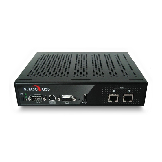
Page 12: The U30 Appliance
INSTALLATION GUIDE 4. PRESENTATION OF THE APPLIANCES 4.2 The U30 appliance The U30 appliance has the following characteristics: Throughput of 200 Mbits/s. 50,000 concurrent connections. 4,000 new sessions per second. Software shutdown button. LEDs from bottom to top: Power/Status/Online. Serial port: for connecting the firewall directly to a PC or modem. -
Page 13: The U70 Appliance
Points 3, 4 and 5: these different ports enable access to the appliance in console mode. The LEDs above the interfaces provide indications as to the throughput. For the U30, an interface with a LED that does not light up indicates a throughput of 10 mbits/s, an interface with 2 LEDs that light up indicate a throughput of 100 mbits/s. -
Page 14: The U120 Appliance
INSTALLATION GUIDE 4. PRESENTATION OF THE APPLIANCES The product is running when the Power LED and the Status and Online LEDs (green) are visible. The Online LED will be the last to light up when the product is running. Traffic will pass through the interfaces. - Page 15 INSTALLATION GUIDE 4. PRESENTATION OF THE APPLIANCES Software shutdown button. LEDs from bottom to top: Power/Status/Online. Serial port: for connecting the firewall directly to a PC or modem. PS2 mini-din port: for connecting a keyboard. VGA port: for connecting a monitor. Button to reset to the default configuration (defaultconfig).
-
Page 16: The U250 Appliance
INSTALLATION GUIDE 4. PRESENTATION OF THE APPLIANCES 4.5 The U250 appliance The U250 appliance has the following characteristics: Throughput of 850 Mbits/s. 400,000 concurrent connections. 6 Gigabit interfaces. 8,500 new sessions per second. Software shutdown button. LEDs from bottom to top: Power/Status/Online. Serial port: for connecting the firewall directly to a PC or modem. -
Page 17: The U450 Appliance
INSTALLATION GUIDE 4. PRESENTATION OF THE APPLIANCES The Status LED will blink (quick blinking every 250 milliseconds) in the event of a major failure of the product (hardware modification, faulty network interface, etc). In this case, do contact your distributor. For an appliance configured in high availability, the Online LED will light up intermittently (for every second it lights up, it will go off for 2 seconds). - Page 18 INSTALLATION GUIDE 4. PRESENTATION OF THE APPLIANCES Point 1: to shut down the software, hold down the software shutdown button for 4 seconds (until the Online (green) LED goes off). NOTE: The fan is directly linked to the power supply. Point 2: the Power LED (yellow) indicates that the product has been plugged in but has been shut down.
-
Page 19: The U1100 Appliance
INSTALLATION GUIDE 4. PRESENTATION OF THE APPLIANCES 4.7 The U1100 appliance The U1100 appliance has the following characteristics: Throughput of 2,800 Mbits/s. 800,000 concurrent connections. 8 Gigabit interfaces. 20,000 new sessions per second. 4.7.1 Front panel Power LED (yellow): when this LED lights up, this means that the firewall is running. Status LED (green). -
Page 20: Rear Panel
INSTALLATION GUIDE 4. PRESENTATION OF THE APPLIANCES 4.7.2 Rear panel Fan grating. Power socket: for plugging in the main power cable. PS2 mini-din port: for plugging in a keyboard. 2 USB ports: for secure configurations and updates. Serial port: for connecting the firewall directly to a PC or a modem. VGA port: for connecting a monitor. -
Page 21: Rear Panel
INSTALLATION GUIDE 4. PRESENTATION OF THE APPLIANCES Point 1: the Power LED (yellow) indicates that the product has been plugged in but has been shut down. The product is running when the Power LED and the Status and Online LEDs (green) are visible. Point 2: When the appliance is starting, shutting down or being updated, the Status LED will light WARNING You are strongly advised against switching off the product when the Status LED is starting,... -
Page 22: The U6000 Appliance
INSTALLATION GUIDE 4. PRESENTATION OF THE APPLIANCES 4.9 The U6000 appliance The U6000 appliance has the following characteristics: Throughput of 5,000 Mbits/s. 2,500,000 concurrent connections. 6 to 24 Gigabit interfaces. 40,000 new sessions per second. 4.9.1 Front panel Online LED. Stand by button: button for switching the appliance on and off. -
Page 23: Rear Panel
INSTALLATION GUIDE 4. PRESENTATION OF THE APPLIANCES The Status LED will blink (quick blinking every 250 milliseconds) in the event of a major failure of the product (hardware modification, faulty network interface, etc). In this case, do contact your distributor. The U6000 firewall has 2 additional indicators –... -
Page 24: The Ng1000-A Appliance
INSTALLATION GUIDE 4. PRESENTATION OF THE APPLIANCES 4.10 The NG1000-A appliance The NG1000-A appliance The NG1000-A appliance has the following characteristics: Throughput of 4,500 Mbits/s. 1,000,000 concurrent connections. 8 Gigabit interfaces on the front panel and 2 Gigabit ports behind = 10 Gigabit interfaces 50,000 new sessions per second. -
Page 25: Rear Panel
INSTALLATION GUIDE 4. PRESENTATION OF THE APPLIANCES Layout n°1 : dmz1 dmz2 dmz3 dmz4 dmz5 dmz6 Layout n°2 : dmz1 dmz2 dmz3 dmz4 dmz5 dmz6 AVERTISSEMENT The lowest firmware version compatible with layout no. 2 is v. 8.1.3. In versions lower than that, the order of network ports is not guaranteed. 4.10.2 Rear panel 2 power sockets for plugging in 2 mains power cables. -
Page 26: The Ng5000-A Appliance
INSTALLATION GUIDE 4. PRESENTATION OF THE APPLIANCES 4.11 The NG5000-A appliance The NG5000-A appliance has the following characteristics: Throughput of 8,500 Mbits/s. 2,500,000 concurrent connections. 16 Gigabit interfaces on the front panel and 2 Gigabit ports behind = 18 Gigabit interfaces 50,000 new sessions per second. -
Page 27: Rear Panel
INSTALLATION GUIDE 4. PRESENTATION OF THE APPLIANCES Layout n°1: dmz1 dmz2 dmz3 dmz4 dmz5 dmz6 dmz7 dmz8 dmz9 dmz10 dmz11 dmz12 dmz13 dmz14 Layout n°2: dmz1 dmz2 dmz7 dmz8 dmz9 dmz10 dmz3 dmz4 dmz5 dmz6 dmz11 dmz12 dmz13 dmz14 AVERTISSEMENT The lowest firmware version compatible with layout no. -
Page 28: Connections
NETASQ firewalls can operate on 230V or 110V. Insert the connector of the power cable (provided with the product) into the power socket on the rear panel of the NETASQ appliance. Next, plug in the pin of the power cable into an appropriate power supply. -
Page 29: Connection For Administering The Appliance
Connect the firewall’s different interfaces to the network interconnection elements with an RJ45 cable. The numbers of the interfaces apply to the U30, U70, U120, U250 and U450 models: The interface identified as “1” on the firewall corresponds to the EXTERNAL interface (called OUT by default) The interface identified as “2”... -
Page 30: U120
INSTALLATION GUIDE 5. CONNECTIONS 5.4.3 U120 Figure 9: U120 interfaces 5.4.4 U250 Figure 10: U250 interfaces 5.4.5 U450 Figure 11: U450 interfaces 5.4.6 U1100 Figure 12: U1100 interfaces 5.4.7 U1500 Figure 13: U1500 interfaces... -
Page 31: U6000
INSTALLATION GUIDE 5. CONNECTIONS 5.4.8 U6000 Figure 14: U6000 interfaces 5.4.9 NG1000-A Figure 15: NG1000-A interfaces on the front panel Figure 16: NG1000-A administration interfaces at the back... -
Page 32: Ng5000-A
INSTALLATION GUIDE 5. CONNECTIONS 5.4.10 NG5000-A Figure 17: NG5000-A interfaces on the front panel Figure 18: NG5000-A administration interfaces at the back 5.4.11 Using a straight cable A straight cable has to be used between a firewall and a hub, a switch or certain modems (depending on the type of modem, a straight or a crossover cable will be necessary). -
Page 33: Antispoofing Mechanism
When this situation arises, there are two solutions – either you change the address that you have just assigned to the administration host (this is what NETASQ recommends), or you reboot the appliance after you have changed its interface. -
Page 34: Physical Installation Of The Appliance
(depending on the type of modem) with a serial link by using a straight serial cable. Router Straight or crossover cable, if the router embeds a hub. Autre firewall Crossover cable Crossover cable NOTE A crossover cable is delivered with the NETASQ firewall. -
Page 35: Preparation Of The Racking Cabinet Or Bay43
U120, U250 and U450 products are sold with a fastening system that has to be added to the product in order to install it. The system is available only by special order for the U30 and U70. 6.2.1 Installing a U30 or U70 6.2.1.1 View from the top... -
Page 36: Installing A U120, U250 Or U450
3. Screws and caged nuts 4. Appliance A system for installing the appliance in a bay can be delivered for the U30 by special order: Installation of the deck in the bay. Screw the supporting deck to the lateral sides of the rack using the caged nuts. -
Page 37: Installing A U1100, U1500 Or U6000
After you have installed this configuration software on your client workstation, you can modify the parameters of the network interfaces on the NETASQ firewall in order to adapt it to your IP addresses and to select the operating mode (transparent or normal). -
Page 38: Initial Connection To The Product
Microsoft Windows XP Service Pack 2 and higher 7.1.2 Preparation of internet access Before installing the NETASQ firewall, ensure that the devices that connect to the internet (if the firewall has to be connected with the internet network) have been appropriately installed and... -
Page 39: Configuration
If you do not know what these parameters mean, we strongly advise that you read up on TCP/IP in order to understand how to configure your NETASQ firewall. These are the intervals defined by the different classes of IP address:... -
Page 40: Registering And Installing The Product
INSTALLATION GUIDE 7. INITIAL CONNECTION TO THE PRODUCT The procedure for configuring your Windows workstation is as follows: Go to the Control panel on your Windows workstation, Select the “Network” menu, Select TCP/IP from the list of network elements, then “Properties”, Indicate the address information required for the network configuration of the workstation: IP address: 10.0.0.250 or the IP address you have selected for your workstation, Subnetwork mask: 255.0.0.0,... -
Page 41: Appendix A: Updating The License
WARNING The NETASQ appliance has to be rebooted when a new license is activated on it. Please refer to the procedure below to find out how to update your product license: Retrieving the license Step 1: Go to NETASQ’s website at... - Page 42 Step 3: Click on “License mangement”. You will then see a list of all the NETASQ UTM products registered in this area. Select the product for which you wish to retrieve the license, by clicking on the product’s serial number.
-
Page 43: Installing The License
Click on the License… button in order to insert the license that you have downloaded from the NETASQ website. Select the downloaded license in order to insert it into the NETASQ UTM product. -
Page 44: Appendix B: Resetting The Firewall
For a U30, U70, U120, U250 and U450 In order to reset a NETASQ U30, U70, U120, U250 or U450 Firewall, take a pointed object (a pen for example). A small switch is located on the appliance’s front panel (between the USB port and the VGA port) and is accessible through a hole in the hood. -
Page 45: Appendix C: Adding An Additional U6000 Network Card
Warning After the appliance has been dismantled, the warranty remains valid if and only if the person who has performed this operation is NETASQ Expert-certified and has abided by the procedure. WARNING The warranty may be rendered null and void in the event any action other than what has been described in this procedure has been carried out. -
Page 46: Steps To Follow
INSTALLATION GUIDE APPENDIX C: ADDING AN ADDITIONAL U6000 NETWORK CARD 4 SX fiber optic ports, LC connector 4 LX fiber optic ports, LC connector PCI-X card 2 copper gigabit ports 4 copper gigabit ports 6 copper gigabit ports ... - Page 47 APPENDIX C: ADDING AN ADDITIONAL U6000 NETWORK CARD Procedure for adding a card The license has to be updated before an additional network card can be installed on a NETASQ firewall. For further information, please refer to Appendix A at the end of this document.
- Page 48 INSTALLATION GUIDE APPENDIX C: ADDING AN ADDITIONAL U6000 NETWORK CARD Adding a PCI-E network card The first additional network card has to be installed in the first free slot on the rear panel (Slot 4). This is the PCI-E port slot directly to the right of the 4 gigabit port QUAD card inserted by default. The diagram below illustrates how a 6-port network card should be inserted.
- Page 49 INSTALLATION GUIDE APPENDIX C: ADDING AN ADDITIONAL U6000 NETWORK CARD Adding a 2nd PCI-E network card The 2 additional network card has to be installed in the second free slot on the rear panel (Slot 5). This is the PCI-E port slot directly to the right of the 1 additional PCI-E card installed on the product.
- Page 50 INSTALLATION GUIDE APPENDIX C: ADDING AN ADDITIONAL U6000 NETWORK CARD Adding a PCI-X network card The PCI-X network card has to be installed directly to the right of the 2 additional PCI-E card installed on the product (PCI-X slot). The interfaces for this card will be added after those that are already present, giving each PCI-X card 6 additional ports as a result.
-
Page 51: Scenarios For Adding Pci-X Cards
INSTALLATION GUIDE APPENDIX C: ADDING AN ADDITIONAL U6000 NETWORK CARD Scenarios for adding PCI-X cards WARNING The interfaces on the firewall will be renumbered when a PCI-X card is added. As such, the cables connected to these interfaces have to be rearranged accordingly. Since the interfaces get renumbered according to the location of cards that have been installed and their port numbers, the scenarios below indicate the procedures to follow for plugging the cables into the appropriate interfaces. - Page 52 INSTALLATION GUIDE APPENDIX C: ADDING AN ADDITIONAL U6000 NETWORK CARD Scenario in which a 6-port PCI-X card is added to a default configuration PCI-E PCI-E PCI-E PCI-X PCI-X QUAD Initial configuration (dmz-1) (dmz-2) (dmz-3) (dmz-4) (out) (in) PCI-E PCI-E PCI-E PCI-X PCI-X QUAD...
- Page 53 INSTALLATION GUIDE APPENDIX C: ADDING AN ADDITIONAL U6000 NETWORK CARD Scenario in which a 2-port PCI-X card is added to a default configuration PCI-E PCI-E PCI-E PCI-X PCI-X QUAD Initial configuration (dmz-1) (dmz-2) (dmz-3) (dmz-4) (out) (in) PCI-E PCI-E PCI-E PCI-X PCI-X QUAD...
- Page 54 INSTALLATION GUIDE APPENDIX C: ADDING AN ADDITIONAL U6000 NETWORK CARD Scenario in which a 6-port PCI-X card is added after a PCI-E card PCI-E PCI-E PCI-E PCI-X PCI-X QUAD Initial configuration em12 (dmz-5) (dmz-11) em13 (dmz-6) (dmz-12) em14 (dmz-1) (dmz-7) (dmz-13) em15 (dmz-2)
-
Page 55: Appendix D: Adding An Ng1000-A And Ng5000-A Extension Module
INSTALLATION GUIDE APPENDIX D: ADDING AN NG1000-A AND NG5000-A EXTENSION MODULE APPENDIX D: ADDING AN NG1000-A AND NG5000-A EXTENSION MODULE The procedure for adding modules to the NG1000-A or NG5000-A firewall takes place in 5 main steps: Step 1 Updating the product license. Step 2 Downloading the license. - Page 56 INSTALLATION GUIDE APPENDIX D: ADDING AN NG1000-A AND NG5000-A EXTENSION MODULE 4 * fiber 1GbE ports (P/N: NA-NG-4GIG-F-E) Duplex LC IEEE 802.3z 1000BASE-SX Optical wavelength: 850nm Max fiber length: 550m on 50/125μm multimode fiber, 300m on 62.5/125μm multimode fiber Class 1 laser safety per EN (IEC) 60825 laser safety standards ...
-
Page 57: Appendix E: Adding A Hard Disk And Activatinga Raid 1 On The Ng1000-A
APPENDIX E: ADDING A HARD DISK AND ACTIVATING A RAID 1 ON THE NG1000-A The procedure for adding an extra hard disk in order to use a RAID 1 on a NETASQ NG1000-A firewall takes place in 6 steps: Step 1 Downloading the license that enables the activation of the RAID 1 feature. - Page 58 A RAID 1 ON THE NG1000-A Follow the steps below to ensure that the installation is correctly performed: Download the new license that enables the activation of the RAID 1 feature from NETASQ’s website. Install the license using NETASQ UNIFIED MANAGER.
-
Page 59: Appendix F: Rebuilding A Raid 1 On An Ng1000-Aor An Ng5000-A
The duration of rebuilding the RAID 1 will vary according to the amount of data on the standard hard disk and the model of your firewall. This may take from several minutes to an hour. NOTE The status of the RAID can be monitored via the NETASQ REAL-TIME MONITOR in the Hardware menu. -
Page 60: Appendix G: Installing The 3G Modem
Contents of the parcel The pack consists of a modem, an antenna with its base and a USB cable. Appliances concerned All U and NG series appliances. Modem Specifications NETASQ 3G-MODEM (NA-EXT-3GM) Frequencies EDGE/GPRS/GSM Quad-band 850/900/1800/1900MHz HSDPA/UMTS Tri-band 850/1900/2100 MHz... -
Page 61: Installation Procedure
INSTALLATION GUIDE APPENDIX G: INSTALLING THE 3G MODEM The Status LEDs Blinking Networks searching Slow blinking Successful 3G/UMTS connection with provider established Green LED Fast blinking Data transfer using 3G/UMTS uplink Steady Successful 3G/UMTS connection but no data transmitting Slow blinking Successful 2G connection with provider established Green + Red LED Fast blinking... -
Page 62: Appendix G: Installing Via The Cd-Rom
INSTALLATION GUIDE APPENDIX G: INSTALLING VIA THE CD-ROM APPENDIX G: INSTALLING VIA THE CD-ROM Insert the installation CD-ROM provided. Once the CD-ROM has been inserted, the administration wizard will launch automatically and guide you step by step. Figure 23: installation wizard on the CD-ROM From the CD-ROM, you will be able to: Configure the network to define the network architecture in which your product will be located. - Page 63 INSTALLATION GUIDE APPENDIX G: INSTALLING VIA THE CD-ROM documentation@netasq.com...
Need help?
Do you have a question about the U30 and is the answer not in the manual?
Questions and answers