Table of Contents
Advertisement
Quick Links
HENKE REVERSIBLE
MULTI-BLADE PLOW
MODEL: I-PLOW MULTI-BLADE: ADAPTIVE + SLUSH + ICE
For Medium to Heavy Trucks
ADAPTIVE + SLUSH + ICE
ADAPTIVE + SLUSH
PARTS BOOK AND INSTALLATION MANUAL
4
SERIAL NUMBER: __________________
VERSION 1.6, NOVEMBER 201
HENKE MANUFACTURING CORPORATION
MANUFACTURERS OF SNOW REMOVAL EQUIPMENT FOR 95 YEARS
3070 WILSON AVE. LEAVENWORTH, KS 66048 PHONE(913)682-9000 FAX(913)682-0300
WWW.HENKEMFG.COM
EMAIL: PARTS@HENKEMFG.COM
WEBSITE ADDRESS :
REV_MULTIBLADE_ADAPTIVE&ICE&SLUSH_EFF_ALL_8400004_016.DOCX
Advertisement
Table of Contents

Summary of Contents for HENKE I-PLOW MULTI-BLADE
- Page 1 HENKE REVERSIBLE MULTI-BLADE PLOW MODEL: I-PLOW MULTI-BLADE: ADAPTIVE + SLUSH + ICE For Medium to Heavy Trucks ADAPTIVE + SLUSH + ICE ADAPTIVE + SLUSH PARTS BOOK AND INSTALLATION MANUAL SERIAL NUMBER: __________________ VERSION 1.6, NOVEMBER 201 HENKE MANUFACTURING CORPORATION MANUFACTURERS OF SNOW REMOVAL EQUIPMENT FOR 95 YEARS 3070 WILSON AVE.
- Page 2 <<THIS PAGE IS INTENTIONALLY LEFT BLANK>> REV_MULTIBLADE_ADAPTIVE&ICE&SLUSH_EFF_ALL_8400004_016.DOCX Page 2 of 34...
- Page 3 In addition to their field-proven standard units, Henke designs and manufactures many plows and hitches to meet specific customer requirements. Call Henke at 913-682-9000 if you need any replacement parts, or if we can provide you any other assistance. REV_MULTIBLADE_ADAPTIVE&ICE&SLUSH_EFF_ALL_8400004_016.DOCX...
- Page 4 Table of Contents Introduction ................................3 Section 1: Safety .................................... 6 Section 2: Setup and Operation ............................... 7 Maintenance ................................8 Section 3: Installation Diagrams ............................ 1 0 Parts Lists for Multi‐Blade Plow ........................ 1 1 3‐Piece Chain Lift Assembly Installation Procedure ................ 1 5 Section 4: Hydraulic And Pneumatic Plumbing ...................... 1 7 Section 5: Trip Devices ................................ 2 4 Section 6: Swivel Plates & Plow Portion Hitches ...................... 2 8 Section 7: Replacement Parts .............................. 3 0 Section 8: Warranty Policy & Procedure ........................... 3 3 REV_MULTIBLADE_ADAPTIVE&ICE&SLUSH_EFF_ALL_8400004_016.DOCX...
-
Page 5: Table Of Contents
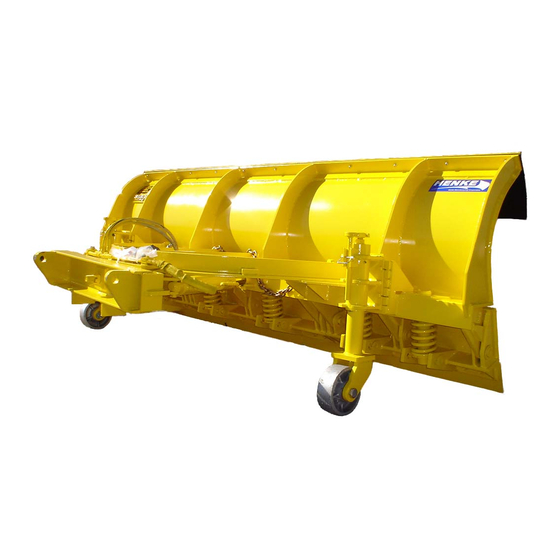
List of Figures FIGURE 1 ‐ Henke Reversible Multi‐Blade Plow w/Adaptive & Slush Blades ....COVER FIGURE 3‐1 ‐ Henke Reversible Multi‐Blade Plow w/Adaptive, Slush, & Ice Blades .... 1 0 FIGURE 3‐2 ‐ Ice & Slush Blade Settings ....................... 1 3 FIGURE 3‐3 ‐ 3‐piece Chain Lift Assembly .................... 1 4 FIGURE 3‐4 ‐ Basic Installations Procedures for 3‐piece Chain Lift Assembly. ...... 1 5 FIGURE 3‐5 ‐ Optional Cable Lift Assembly .................... 1 6 FIGURE 4‐1 – Pneumatic Plumbing For Slush & Ice Blades .............. 2 0 FIGURE 4‐2 – Pneumatic Plumbing, Bulkhead Plate (Parts From 6379101 & 6379100) .. 2 1 FIGURE 4‐3 – Pneumatic Plumbing, Cylinders (Parts From 6379101 & 6379100) .... 2 2 FIGURE 4‐4 – Pneumatic Multi‐Blade Control Kit (6379001) ............ 2 3 FIGURE 5‐1 ‐ Enclosed Spring Trip with Attachments . - Page 6 <<THIS PAGE IS INTENTIONALLY LEFT BLANK>> REV_MULTIBLADE_ADAPTIVE&ICE&SLUSH_EFF_ALL_8400004_016.DOCX Page 6 of 34...
- Page 7 SAFETY SECTION AK EXP - Extreme Duty Alaska APR/APX CITE - Compression Trip Edge EXP - Expressway Reversible Plow FV - Folding Vee-Plow HH - Utility Dozer Blade HHJR - Junior Dozer Blade iPlow ISL T - Light line J Torsion Spring Trip Edge LB30 - R - Dozer Blade MAT - Montana Asphalt Topper PCI-Power Circle Plow...
- Page 8 SAFETY GENERAL SAFETY INSTRUCTIONS AND PRACTICES A careful operator is the best operator. Safety is of primary importance to the manufacturer and should be to the owner/operator. Most accidents can be avoided by being aware of your equipment, your surroundings, and observing certain precautions.
- Page 9 HENKE Snow Plows use ba lanced and matched system components for plows, carriers, and other components. These p arts are made and tested to HENKE specifications. Non-genuine or “will fit" parts do not consistently meet these specifications. The use of non-genu ine or “will fit” parts may reduce Snow Plow performance, void HENKE warranties, and present a safety hazard.
- Page 10 SAFETY All Safety Sh ields, Guards and other Protective Safety devices sh ould be used and maintained in goo d working condition. All safety devices should be inspected carefully at least daily for missing or broken components. NEVER REMOVE PROTECTIVE SHIELDS AND GUARDS! NEVER MODIFY OR CUT PROTECTIVE SHIELDS OR GUARDS! When shields or guards are removed to access areas for maintenance, they must be replaced and be in good condition before operating.
- Page 11 SAFETY Prolonged operation of the Snow Plow ma y cause operator boredom and/or fatigue affecting the safe operation of the Snow Plow and Truck or Power unit. It is recommended that the op erator take scheduled work breaks to help prevent these potentially impaired operating conditions.
- Page 12 SAFETY Always wear a seat belt while driving the equipment during operation and transport. Serious injury or even death could result fr om falling from the operator’s station or from being involved in a collision. (SNPO-05) Start the engines only when seated and belted in th e operator’s seat. Operate the equipment controls only while properly seated with th e seat belt secur ed around you.
- Page 13 SAFETY Unplowed snow, piled ice and debris, and snow drifts left behind the equipment might pose a driving hazard to vehicle traffic colliding with the debris or losing traction on the material. It is r ecommended to post warning signs alerting driver’s of th e equipment operation presence and the need to reduce vehicle speed.
- Page 14 SAFETY Extreme caution should be used by th e operator when operating near passersby. Stop snow plowing if a passerby comes within 25 feet of the plow to prevent possible passerby injury or death from being struck by the equipment or from a thrown object. (SNPO-31) Under certain conditions, the Snow Plow is capable of propelling objects up to 75 feet.
- Page 15 SAFETY CONNECTING OR DISCONNECTING IMPLEMENT SAFETY INSTRUCTIONS AND PRACTICES Do not stand or allow bystander or coworkers between the attachment and the truck or powe r unit while ins talling or disconnecting the attachment. Ke ep hands and body clear of th e attachment and the attachment mounts.
- Page 16 SAFETY MAINTENANCE AND SERVICE SAFETY INSTRUCTIONS AND PRACTICES Perform service, repairs and lubrication according to the maintenance section. Ensure the unit is properly lubricated as specified in the lubrication schedule and all bolts and nuts are properly torqued. Failure to properly service, repair and maintain this Implement in good operating condition could cause component failure and possible serious injury or even death.
- Page 17 SAFETY Never leave the Snow Plow unattended while the plow is in the raised position. Accidental operation of the lifting lever or a hydraulic failure may cause a sudden drop of the unit which could result in injury or death by crushing. If the plow must be raised for inspection or service securely block up and support the Plow to prevent it falling.
- Page 18 SAFETY Do not operate this equipment with hydraulic oil or fu el leaking. Oil and fuel are expensive and their presence could present a hazard. Do not check for leaks with your hand! High-pressure oil streams from breaks in the line could penetrate the skin and cause tissue damage including gangrene.
- Page 19 SAFETY Transporting Safety Instructions and Practices Transport the Truck, Power Unit, and Snow Plow only at safe speeds. Serious accidents and injuries can result from driving this equipment at unsafe speeds. Become familiar with the driving characteristics of the equipment and how it han dles before operating or transporting on streets and highways.
- Page 20 SAFETY Federal Laws and Regulations This section is inten ded to explain in broad terms the concept and effect of federal laws and regulations concerning employer and employee equipment operators. This section is not intended as a legal interpretation of the law and should not be considered as such.
- Page 21 Nylock Nut, 1/4-20 Instructions: Follow these instructions to position the above items to your Henke product for safety and professional appearance. Apply on clean surfaces only. They should be properly applied and kept in good condition. If a decal is worn out, torn, or otherwise defaced, call us for an immediate replacement at 1-913-682-9000, or 1-888-682-9010.
- Page 22 DECALS 1. Position 7331007, 7331005, and 7331004 to the LEFT of 7331011, 7331012, and 7331003 of the Moldboard as shown. 1.5" 3” 3/4" 3/4" 3/4" 7331007 7331012 7331005 7331011 7331004 7331003 2. Position 7330012 Serial Plate and 7300047 Manual Canister as shown. 7300047 7330012 6”...
- Page 23 DECALS 3. Position 7331010 (Qty. 2) as shown. Close to stop block In Line with edge and Smooth AWAY from edge. 4. Position 7331009 (Qty. 2) as shown. Centered & Visible above Ear DECALS - I PLOW.DOC...
- Page 24 DECALS 5. Position 7330014, Henke Logo in. CENTERED 3/4" 6. Position 7331006 decals (Qty. 2) on each hydraulic cylinder as shown. In line with top of Cylinder Top cylinder & Visible. Preferably on Port side of cylinder. DECALS - I PLOW.DOC...
- Page 25 REVERSIBLE PLOW SET UP AND OPERATION ALWAYS OPERATE PLOW WITH PUSHFRAME PARALLEL TO THE GROUND. This will help provide proper moldboard layback angle and pr oper plowing position, which will allow proper operation of the plow trip mechanism, and optimal overall plow performance.
- Page 26 IN SEASON MAINTENANCE Snow removal equipment must be cared for and maintained regularly. Daily or pr e- route inspection and maintenance are necessary. Failure to do so may affect efficiency and safety. A visual inspection must be c arried out after every 8 hour s of operation. Look for damaged components, bends, cracked welds or hydraulic leaks.
- Page 27 END OF SEASON SNOW PLOW MAINTENANCE GROUND ENGAGING COMPONENTS CUTTING EDGES & GUARDS: Replace any broken cutting edges, unevenly or excessively worn cutting edges, and broken or worn wear guards. RUNNING GEAR: Replace broken, worn, or missing running gear shoes, and any damaged adjuster leg components.
- Page 28 FIGURE 3-1 – Henke Reversible Multi-Blade Plow With Adaptive Front Blade and Slush Blade...
- Page 29 TABLE 3-1 – Henke Reversible Multi-Blade Plow, Parts List Item No. Qty. Part No. Description 7050043 Cotter Pin, 3/16 X 2.5 7050001 Cotter Pin, 1/4 X 3.0 7030023 Slotted Nut, 1 1/4-7 7030024 Slotted Nut, 1 1/2-6 7040014 Flat Washer, 1 1/4 Hardened, SAE...
- Page 30 TABLE 3-1 – Henke Reversible Multi-Blade Plow, Parts List (Continued) Item No. Qty. Part No. Description 4600-0040 Pin, 1.0 X 22.13 (11' Plow) 4600-0026 Pin, 1.0 X 28.13 (12' Plow) 7080658 Pneumatic Cylinder 7040007 Flat Washer, 3/4 Hardened, SAE 7050105...
- Page 31 REV_MULTIBLADE_ADAPTIVE&ICE&SLUSH_EFF_ALL_8400004_016.DOCX Page 13 of 34...
-
Page 32: Figure 3-3 - 3-Piece Chain Lift Assembly
FIGURE 3-3 – 3-Piece Chain Lift Assembly TABLE 3-2 – 3-Piece Chain Lift Assembly Item No. Qty. Part No. Description Varies Lower Chains, 3/8 GR. 70 (Call Henke for (Length Varies) Part Number) 1300-2700 Upper Chain, 7/16 x 20” 7060001 Shackle, 7/16 2-Ton, Round Pin... - Page 33 Set upper chain length so that chains become tight exactly when lift arm reaches horizontal position. FIGURE 3-3 – Basic Installation Procedure for 3 Piece Chain Level Lift: 1. Attach plow to hitch using Pin-On or Quick-Hitch connection. 2. Raise hitch lift cylinder until hitch lift arm is approx. 5° below horizontal (with plow end of the lift arm being a little lower than hitch end).
-
Page 34: Figure 3-5 - Optional Cable Lift Assembly
TABLE 3-3 – Optional Cable Lift Assembly, Parts List FIGURE 3-5 – Optional Cable Lift Assembly REV_MULTIBLADE_ADAPTIVE&ICE&SLUSH_EFF_ALL_8400004_016.DOCX Page 16 of 34... - Page 35 TABLE 4-1 – Hydraulic Components Hydraulic Reversing Assembly Qty. Part No. Description 1300-0276 Cushion Valve Plate 7020371 Hex Capscrew 5/16-18 x 2.5 GR. 5 7030086 Nylock Nut, 5/16-18 7040003 Flat Washer, 5/16 Hardened, USS 7080322 Cushion Relief Valve, 2000 PSI (Standard for Most Plows) 7080133 Cushion Relief Valve, 2500 PSI...
-
Page 36: Table 4-2 - Pneumatic Components
TABLE 4-2 – Pneumatic Components Pneumatic Ice Blade Assembly (Henke Item #6379101) Item Qty. Part No. Description 239" 7099001 Air Hose, .248 ID X .375 OD Poly 7099004 269PP-06-06, Elbow 90° 7099003 3300-BH-06-1.31, Bulkhead Coupler 7099002 272PP-06-06-06, Tee 7050105 Clevis Pin, 3/4 X 3 7050113 Cotter Pin, 1/8 X 1.5... - Page 37 Section 4 – Pneumatic Plumbing for Squeegee and Ice Blade PNEUMATIC PLUMBING RECOMMENDATIONS Ensure that your truck’s auxiliary air tank provides for primary tank priority pressure, so that priority flow is always maintained to the critical systems of the truck, such as braking.
- Page 38 FIGURE 4-1 - Pneumatic Plumbing for Slush and Ice Blades...
- Page 39 FIGURE 4-2 - Pneumatic Plumbing, Bulkhead Plate (Parts are included in Henke Item No. 6379101 & 6379100) NOTE: Numbering Coincides with Table 4-2 REV_MULTIBLADE_ADAPTIVE&ICE&SLUSH_EFF_ALL_8400004_016.DOCX Page 21 of 34...
- Page 40 9 & 11 6 & 8 FIGURE 4-3 - Pneumatic Plumbing, Cylinders (Parts are included in Henke Item No. 6379101 & 6379100) NOTE: Numbering Coincides with Table 4-2...
- Page 41 20 13 12 & 13 14 & 15 FIGURE 4-4 – Pneumatic Multi-Blade Control Kit (Henke Item No.6379001) NOTE: Numbering Coincides with Table 4-2...
- Page 42 TABLE 5-1 – Enclosed Spring Trip w/ Attachments, Parts List FIGURE 5-1 – Enclosed Spring Trip (EST) w/ Attachments...
-
Page 43: Figure 5-2 - Enclosed Spring Trip Assembly (Est)
NOTE: ENTIRE ASSEMBLY MAY BE PURCHASED AS 139-0174M (See Safety Warning) FIGURE 5-2 – Enclosed Spring Trip Assembly (EST) TABLE 5-2 – Enclosed Spring Trip Assembly, Parts List Item No. Qty. Part No. Description 139-0753 Housing Assembly 139-0886 Guide Tube Assembly 139-0088 Shaft Assembly 1300-1562... -
Page 44: Figure 5-3 - Enclosed Spring Trip Adjustment
Suggested Layback Angle Single EST = 15° Factory Setting. Do Not Exceed 25°. Dual EST = 36R, 41R = 15° Factory Setting. Do Not Exceed 25°. Dual EST = 48R = 20° Factory Setting. Do Not Exceed 27°. NOTE: If Different Adjustment of the pl ow moldboard is needed, follow the above diagram. -
Page 45: Figure 5-4 - External Compression Trip Assembly (Ect)
TABLE 5-3 – External Compression Trip Assembly, Parts List FIGURE 5-4 – External Compression Trip Assembly (ECT) -
Page 46: Figure 6-1 - Universal Quick Hitch (Uqh)
TABLE 6-1 –Universal Quick Hitch, Parts List Item No. Qty. Part No. Description Assembly and Adjustment Instructions: 469-0014 UQH Plow Portion Weldment 1. Install levers (items 2 & 3) using hardware indicated. 1400-0426 Lever Left Check handle function. If mechanism is tight, loosen 1400-0427 Lever Right locknuts just enough to allow smooth operation. -
Page 47: Figure 6-2 - Swivel Plates & Plow Hitches
FIGURE 6-2 – Swivel Plates & Plow Hitches Many different types of swivel plates and plow hitches are available. Samplings are shown below. Please call Henke Manufacturing for part numbers. Swivel Plates with Standard Ears Swivel Plates with Long Ears... - Page 48 6. Henke's rubber cutting edges feature a minimum tensile strength of 2000 psi and a maximum DIN rating of 150, and last much longer in service than lower quality rubber cutting edges available from some other suppliers.
-
Page 49: Table 7-2 - Cutting Edge Hardware
TABLE 7-2 – Cutting Edge Hardware TYPE LENGTH PART NO. USES/NOTES 2” 7150001 2 ½” 7150003 3” 7150002 FOR STANDARD CUTTING 3 ½” 7150103 PLOWBOLTS EDGES AND WEAR 4” 7150105 5/8-11 GRADE 8 GUARDS 4 ½” 7150106 5” 7150108 7150107 6”... -
Page 50: Table 7-3 - Henke Curb Guards & Wear Guards
TABLE 7-3 – Henke Curb Guards & Wear Guards Wrap-Around Curb Guards, Steel 7150122 6”, Left 7150121 6”, Right 7150117 8”, Reversible Wrap-Around Curb Guards, Chrome-Carbide Weld Deposit on Wrap-Around Corner 7150125 6”, Left 7150126 6”, Right 7150115 8”, Left 7150118 8”, Right... - Page 51 Warranty claims must be filled within 30 days of repair work during the one year warranty period and will be honored only if the completed warranty registration form has been returned. Henke reserves the right to require proof of purchase of original Henke replacement parts.
- Page 52 These may be n ecessary for a prop er repair rec ommendation and procedure. Henke will respond w ith a w ritten labor hour allowance for Henke participation on a faxed claim form and will ship any required replacement parts. I f necessary, a r epair procedure will be included on the claim form.
Need help?
Do you have a question about the I-PLOW MULTI-BLADE and is the answer not in the manual?
Questions and answers