Table of Contents
Advertisement
Advertisement
Table of Contents

Summary of Contents for Ikegami BS-79
- Page 1 BS-79 BASE STATION OPERATION MANUAL 0212 1st Edition (U) (E)
- Page 2 Copyright © 2002 Ikegami Tsushinki Co., LTD. We reserve the copyright on the software we create. No portion of this publication may be reproduced in any form, or by any means, without prior written permission from Ikegami Tsushinki Co., LTD.
- Page 3 Safety Precautions The safety precautions on use of BS-79 are described below. Please read these precautions thoroughly before use. 1. Hazard Alert Symbols and Signal Words Concerning Safety in this Manual This manual employs the following "hazard alert symbol", "signal words" that indicate the danger levels, "Notice"...
-
Page 4: Table Of Contents
5. TROUBLE SHOOTING ... 5.1 When the CABLE or TEMP. Indicators Are On ... I Cleaning optical connectors ... 5.2 When the ALARM Indicator Is On ... I Displaying the self-diagnostic information screen ... BS-79 0212 VOL1 (U) (E) CONTENTS BS-79... -
Page 5: Overview
HD (when the SD module is selected) Capable of DC operation Supplying +12 VDC to the BS-79 can also drive the camera head. This function allows operation using +12 V supplied from ordinary vehicles to provide mobility. - Page 6 100/117 VAC ±10% +10.8 to +16 VDC When signals are transmitted over a distance of 1000 m with a camera head (HDK-79D/E), 2-inch B/W VF, and BS-79 (when the down converter is installed): About 250 VA 16. Camera cables Optical fiber cable:...
- Page 7 218.5 × 165 × 430.5 [mm] (W × H × D) I Applicable standards 1. Safety standard None 2. Quality control 3. COCOM Inapplicable BS-79 0212 VOL1 (U) (E) 1. OVERVIEW 1 - 3 0°C to +45°C 30% to 90% -30°C to +60°C 10 to 57 Hz 0.3 mmp-p 57 to 150 Hz 19.6 m/s...
-
Page 8: External View
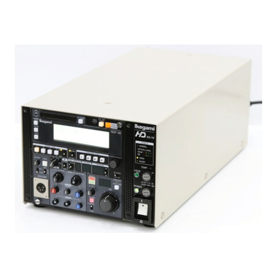
1 - 4 1. OVERVIEW 1.4 External View BS-79 BS-79 0212 VOL1 (U) (E) -
Page 9: Name And Function Of Each Part
• OPEN: On when no camera cable is connected or there is an open in the camera cable. • SHORT: On when a short circuit occurs in the cameral cable or connector due to a cause such as water. BS-79 0212 VOL1 (U) (E) 2 - 1 BS-79... -
Page 10: Inside Of The Front
SD SC PHASE (FINE) control LOCAL/REMOTE switch INCOM LEVEL (ENG) control INCOM LEVEL (PROD) control PRIVATE/COMMON switch RCP ON/OFF switch RBK/RCP connector DC output indicators SPARE FUSE holder BS-79 0212 VOL1 (U) (E) ATTENTION WARNING Green Green Green Yellow Green Yellow... - Page 11 BS. 18 DC output indicators On when the voltage supplied to each BS module is output normally. 19 SPARE FUSE holder Holder for spare fuses Two fuses are mounted at shipment. BS-79 0212 VOL1 (U) (E) 2 - 3 BS-79...
-
Page 12: Back
This connector can be used only when an RCP-50 is mounted on the front panel of the BS. 6 TALLY OUT connector Tally signals for picture monitoring are output. BS-79 0212 VOL1 (U) (E) ● RET (SD) module ● RET (HD) module ● D1 RET module ●... -
Page 13: Control Panel
For the MON (HD) module, the HDTV YPbPr or RGB signals (switched using a switch in the module) are output. For switching of the component signals, see Section 4.3, "Setting the Component Signals." BS-79 0212 VOL1 (U) (E) 2 - 5 Use the BS-79... -
Page 14: Installation And Connection
INSTALLATION AND CONNECTION 3.1 System Setup Diagram HDK-79D/E RBK-79 3. INSTALLATION AND CONNECTION MIC-1 MIC-2 (PROD/ENG) Fiber Cable max 1000m FA-79 DC IN AC IN BS-79 + RCP-50 BS-79 0212 VOL1 (U) (E) 3 - 1 Headsets Headset BS-79... -
Page 15: Types Of Operation
BS-1 BS-8 BS-79 WFM REMOTE AC IN DC IN WFM REMOTE OCP/CCP (with XRC-314 Case) AC IN WFM REMOTE OCP/CCP MCP/CCP AC IN PM , WFM , MCP/CCP AC IN BS-79 0212 VOL1 (U) (E) WFM CONT COMM BS-1 BS-8... - Page 16 BS-24 BS-25 BS-32 BS-33 BS-40 3. INSTALLATION AND CONNECTION WFM REMOTE OCP/CCP MCP/CCP AC IN PM , WFM , MCP/CCP AC IN BS-79 0212 VOL1 (U) (E) WFM CONT COMM BS-1 BS-8 CSU-1 BS-9 BS-16 CSU-2 COMM BS-17 BS-24 CSU-3...
-
Page 17: Device Connection Diagram
3.3 Device Connection Diagram CP Cable (Max.300m) Fiber Cable (Max.1000m) To CAMERA HEAD AC IN BS-79 CP Cable (Max.300m) WFM Cont Cable (Max.5m) Coaxial Cable (Max.50m 5C-2V) Coaxial Cable (Max.50m 5C-2V) BS-79 0212 VOL1 (U) (E) Iris remote controller Remote Cable... -
Page 18: Connecting A Control Panel
3.4 Connecting a Control Panel On the front of the BS-79, you can mount an RBK-79 or RCP-50 as the BS front panel. For how to mount the panel, see Section 3.5, "Mounting a BS Front Panel." On the back of the BS-79, you can connect an OCP, MCP, CCP, CSU, or RCP-50 to each of the OCP/CCP and MCP/CCP connectors. -
Page 19: Mounting A Bs Front Panel
3. INSTALLATION AND CONNECTION 3.5 Mounting a BS Front Panel On the front of the BS-79, you can mount an RBK-79 or RCP-50 as the BS front panel. [Mounting an RBK-79] 1. Place the BS MAIN POWER switch to the "O" (off) position. -
Page 20: Pin Assignment Of Connectors
This connector is used to connect a camera head to the BS. BS side : FXW.3K.93C.CLC (Lemo) Cable side : PUW.3K.93C.CLMC96 or equivalent Function Direction BS-79 0212 VOL1 (U) (E) 3 - 7 External Interface Use a dedicated DC cable (PSC574). External Interface BS-79... - Page 21 Function Direction This is a microphone voice output connector (600-ohm balanced output). BS side : HA16PRH-3S (Hirose) Cable side : XLR-3-12C (3-pin male plug) or equivalent Function Direction - - - BS-79 0212 VOL1 (U) (E) External Interface External Interface...
- Page 22 3. INSTALLATION AND CONNECTION This connector is used to connect a remote controller. BS side : HR10A-13R-20SC (Hirose) Cable side : XR10A-13P-20PC (20-pin male plug) or equivalent Function Direction - - - BS-79 0212 VOL1 (U) (E) 3 - 9 External Interface BS-79...
- Page 23 • COMMON TALLY OUT can be used to control R and G tally signals simultaneously. BS-79 This connector is used to output tally control signals. BS side : PRC05-RB5F1 (Tajimi) Cable side : PRC05-P5M (5-pin male plug) or equivalent Function Direction R TALLY G TALLY BS-79 0212 VOL1 (U) (E) External Interface...
- Page 24 Cable side : PRC03-12A10-7M10.5 (7-pin male plug) or equivalent Function Direction - - - 528 WFM CN827 - MTP9 BS-79 0212 VOL1 (U) (E) 3 - 11 External Interface FUNCTION STAIR -15 V (+) OUT K370 SEL -15 V (-) OUT...
- Page 25 R - Y (V AXIS) SEL 1 LINE (1H) RGB ENABLE DB - 25S - N DB - C2 - J9 - S6 (HOOD) (DB - 25P) BS-79 0212 VOL1 (U) (E) 1740 FUNCTION SPARE 1 SPARE 2 SPARE 3 SPARE 4...
- Page 26 +TIME CODE IN -TIME CODE IN PRESET1 PRESET2 PRESET3 PRESET4 PRESET5 PRESET6 PRESET7 PRESET8 DB - 25P - N DB - C8 - J10 - B2-1 (HOOD) (DB - 25S) BS-79 0212 VOL1 (U) (E) 3 - 13 STORE BS-79...
- Page 27 This connector is used to input tally control signals. BS side : PRC03-21A10-7M (Tajimi) Cable side : PRC03-12A10-7F10.5 (7-pin female plug) or equivalent Function Direction - - - BS-79 0212 VOL1 (U) (E) External Interface ※ 24 V ※ 24 V MAKE POWER...
- Page 28 This connector is used to connect an external intercom system. BS side : TRC01-A25R24MA (Tajimi) Cable side : TRC01-25P24FA (24-pin female plug) or equivalent Function Direction - - - - - - BS-79 0212 VOL1 (U) (E) 3 - 15 External Interface BS-79...
- Page 29 ON position RTS position OFF position These connectors are used to connect a control panel. BS side : PRC05-RB8F (Tajimi) Cable side : PRC05-PB8M (8-pin male plug) or equivalent Function Direction BS-79 0212 VOL1 (U) (E) S1, 4 External Interface...
-
Page 30: Mounting A Rack-Mount Adapter
Connect both sides of the rack-mount adapter to the corresponding lockings. Front of a rack mount dedicated to the BS-79 M5-10* 4. Mount an ADP plate on the base of the BS-79 with four screws. ADP PLATE 3. INSTALLATION AND CONNECTION... - Page 31 3 - 18 3. INSTALLATION AND CONNECTION 5. Secure the BS-79 (with an ADP plate) on the rack-mount adapter with two screws. M3-6 6. To mount a RACK BLK, secure the RACK BLK on an ADP plate with two screws.
-
Page 32: Settings
2. Set BARS to "ON", and check BS PM OUT on the monitor. 3. Press the MENU switch. The main menu dedicated to the BS-79 is displayed on the monitor. "SCREEN/FILTER" is displayed only when the U/C and D/C modules are installed. - Page 33 --- OPE. GUIDE --- MENU SEL : [SEL] KNOB ENTER : [ENTER] KEY BS-79 0212 VOL1 (U) (E) QUIT Function Turns the BARS TITLE character display on or off. Edits BARS TITLE characters. Sets the position where the BARS TITLE characters are displayed.
- Page 34 2-OFF 2-OFF 2-OFF 3-OFF 3-OFF 3-OFF 4-OFF 4-OFF 4-OFF 5-OFF 5-OFF 5-OFF 6-OFF 6-OFF 6-OFF 7-OFF 7-OFF 7-OFF 8-OFF 8-OFF 8-OFF --- OPE. GUIDE --- QUIT : [ENTER] KEY BS-79 0212 VOL1 (U) (E) 4. SETTINGS 4 - 3 BS-79...
-
Page 35: Bars Title Function
Suitable for shooting sports videos for which subjects move quickly. (3) BARS TITLE function Select and confirm "BARS TITLE" on the BS-79 main menu screen. On the BARS TITLE ENTRY screen, selecting and confirming "QUIT" displays the previous screen again. Press the QUIT switch on the LCD touch sensor panel to exit from the menu. - Page 36 DISPLAY: OFF TITLE EDIT POSITION --- OPE. GUIDE --- CHAR.SEL : [SEL] KNOB CURS.SEL : [NEXT] KNOB ENTER : [ENTER] KEY QUIT ENTRY BS-79 #&()[]-/*+=~: ., ’ 0123456789 ABCDEFGHIJKLMNOP QRSTUVWXYZ BS-79 0212 VOL1 (U) (E) 4. SETTINGS 4 - 5 BS-79...
- Page 37 7. Press the ENTER switch on the LCD touchpanel to exit from the display position setting screen. BS-79 ** BARS TITLE ENTRY ** QUIT DISPLAY: OFF TITLE EDIT POSITION --- OPE. GUIDE --- H-POSI. [SEL] KNOB V-POSI. : [NEXT] KNOB ENTER : [ENTER] KEY BS-79 0212 VOL1 (U) (E)
- Page 38 (absolute value control) and the MCP uses rotary encoders (relative value control). Control may be performed for one level control item using multiple remote control panels connected to the BS-79. There are two operating modes, split mode and parallel mode. In the split mode, one of the remote control panels is granted the right to control the camera head.
- Page 39 OCP/CCP MCP/CCP Blank panel (RBK-79) BS-79 Blank panel (RBK-79) BS-79 Blank panel (RBK-79) BS-79 0212 VOL1 (U) (E) ※ RCP-50 ※ : A dedicated storage box (XRC-314) is required. ※ RCP-50 OCP/CCP MCP/CCP ※ : A dedicated storage box (XRC-314) is required.
-
Page 40: Setting The Tally Mode
You can select "MAKE" or "POWER" using switches S301 and S302 in the INCOM module. ■ MON (SD) module ■ MON (HD) module ■ INCOM module MAKE POWER S302 BS-79 0212 VOL1 (U) (E) 4. SETTINGS 4 - 9 MAKE POWER S301 BS-79... -
Page 41: Setting The Genlock Phase Mode
The SDTV output and 3-value SYNC are in phase. The phase of the HDTV output leads the phase of the 3-value SYNC by 90H. BS-79 0212 VOL1 (U) (E) Do not change the switch position (always in the "OFF" position). tri-Level SYNC... -
Page 42: Setting The Number Of Intercom Lines
The intercom from the PROD system is merged into the ENG system and one line (ENG system) is connected to the external system. For ENG and PROD on the camera head, the same line can be used for conversation. ■ AUDIO module 1LINE BS-79 0212 VOL1 (U) (E) 4. SETTINGS 4 - 11 2LINE BS-79... -
Page 43: Interchanging The Eng And Prod Intercom Systems
PROD system. • ENG/PROD For the system, the ENG system is connected to the PROD system and the PROD system is connected to the ENG system. BS-79 ■ AUDIO module ENG/ PROD BS-79 0212 VOL1 (U) (E) ENG/ ENG/ ENG/ PROD... -
Page 44: Trouble Shooting
At this time, self-diagnostic information is displayed on the picture monitor. (See Section 5.2, "When the ALARM Indicator Is On.") Action : Check whether the fans are normal. 5. TROUBLE SHOOTING CABLE NORMAL OPTICAL LEVEL HEAD OPEN SHORT TEMP. BS-79 0212 VOL1 (U) (E) 5 - 1 CABLE indicators TEMP. indicator BS-79... -
Page 45: I Cleaning Optical Connectors
Top: Present only in female connectors. Plug (female) Ferrules Plug (male) Ferrules receptacle (female) Ferrules receptacle (male) Ferrules BS-79 0212 VOL1 (U) (E) Alignment sleeve : Present only in female connectors. Ferrule Top: Present only in female connectors. Alignment sleeve Ferrule Ferrule Alignment sleeve... - Page 46 (vertically or horizontally) when cleaning the Ferrule. Do not move the swab back and forth when wiping the Ferrule. Never move the swab round and round. BS-79 0212 VOL1 (U) (E) 5. TROUBLE SHOOTING Fiber cable Screw (Good) Ferrule...
- Page 47 3. Align the extractor with the alignment sleeve and turn the extractor clockwise until it stops (about eight to ten turns). 4. Pull the extractor on the straight. Leave the alignment sleeve attached to the extractor. BS-79 Extractor Alignment sleeve BS-79 0212 VOL1 (U) (E) Extractor...
- Page 48 (vertically or horizontally) when cleaning the Ferrule. Do not move the swab back and forth when wiping the Ferrule. Never move the swab round and round. Extractor BS-79 0212 VOL1 (U) (E) 5. TROUBLE SHOOTING (Good) Ferrule (Bad) Ferrule...
-
Page 49: When The Alarm Indicator Is On
5.2 When the ALARM Indicator Is On The BS-79 has a self-diagnostic function which monitors failures in the BS itself and camera head. This function starts operation at the same time that the power switch is turned on and is operating all the time during operation. If a failure occurs in the BS or camera head, this function immediately detects the failure and makes the ALARM indicator on the control panel blinking. - Page 50 The screen display mode is letter box. LOCK The external synchronization signal is input and operation is normal. UNLOCK The external synchronization signal is input, but operation is performed asynchronously. BS-79 0212 VOL1 (U) (E) 5. TROUBLE SHOOTING Meaning 5 - 7 BS-79...
- Page 51 Dec. 2002 Ikegami Tsushinki Co.,Ltd. - All rights reserved. Reproduction or duplication, without permission of Ikegami Tsushinki Co., Ltd. of editorial or pictorial content in whole or in part, in any manner, is prohibited. - Specifications and design are subject to change without prior notice.
- Page 52 37 Brook Avenue, Maywood New Jersey 07607, U.S.A. Phone: (201)368-9171, Telex: 219034 ITCNJ UR, Fax: (201)569-1626 I Ikegami Electronics (Europe) GmbH Ikegami Strasse 1, 41460 Neuss 1, F.R. Germany Phone: (02131)123-0, Telex: 17-2131365=IKE, Fax: (02131)102820 Property of: : : : :...
Need help?
Do you have a question about the BS-79 and is the answer not in the manual?
Questions and answers