Table of Contents
Advertisement
Quick Links
Dr. Staiger, Mohilo + Co GmbH
Dr. Staiger Mohilo
Industrielle Messtechnik und Prüfsysteme
Industrial measurements and test systems
1509e / 05.11.2004 / MHe
Operation Manual
UMV 2000
User prompting / pin assignment
Data logging software
Interface commands
SOFTWARE-VERSION
DATE OF ISSUE
DESIGNATION
Dr. Staiger, Mohilo+Co GmbH
Maierhofstraße 35, D-73547 Lorch
Telefon (07172) 184-0, Telefax
(07172) 184-500
E-Mail:
info@staiger-mohilo.de
Internet: http:// www.staiger-
mohilo.de
Operation manual no. 1509
UMV 2000
Operation manual no. 1509
Maierhofstrasse 35
Tel.: 0 71 72 / 184-0
V3.10W 2003-10-09
2004-11-05
Operation manual UMV 2000
D – 73547 Lorch
Fax: 0 71 72 / 184-500
page 1 / 69
Advertisement
Table of Contents

Summary of Contents for Dr. Staiger Mohilo UMV 2000
- Page 1 UMV 2000 User prompting / pin assignment Data logging software Interface commands V3.10W 2003-10-09 SOFTWARE-VERSION DATE OF ISSUE 2004-11-05 Operation manual UMV 2000 DESIGNATION Dr. Staiger, Mohilo+Co GmbH Maierhofstraße 35, D-73547 Lorch Telefon (07172) 184-0, Telefax (07172) 184-500 E-Mail: info@staiger-mohilo.de Internet: http:// www.staiger-...
-
Page 2: Table Of Contents
2.2 The measuring mode ..........................9 2.3 Menu configuration ..........................9 2.3.1 Submenu sensor..........................10 2.3.1.1 Configuring output signals of a sensor in the UMV 2000 ............. 11 2.3.1.2 Additional display (peak value storage, low-pass filter setting)............. 13 2.3.2 Alarm function ........................... 14 2.3.2.1 Quantities to be monitored ...................... - Page 3 2.10.3.6 Defining of low-pass filter......................35 2.11 Service-functions ..........................36 3. CONNECTIONS ON THE INSTRUMENT REAR PANEL ............. 37 4. TECHNICAL SPECIFICATIONS OF THE UMV 2000 ..............40 5. DATA LOGGING SOFTWARE..................... 43 5.1 General ..............................43 5.2 System requirements and installation....................44 5.3 The main window ..........................
- Page 4 Dr. Staiger, Mohilo + Co GmbH 6. INTERFACE COMMANDS ......................62 6.1 Command *IDN............................. 62 6.2 Command MEASure ..........................62 6.3 Command TRACe ..........................63 6.4 Command *ESR ............................ 65 6.5 Command *OPC............................ 66 6.6 Command SET ............................66 6.7 Command SELect..........................67 6.8 Command INP:GAIN:MULT .......................
-
Page 5: General Information
UMV 2000. The UMV 2000 feeds passive strain-gauge sensors with a unipolar voltage of 5V. By employing the 6- conductor techniques voltage drops through feed lines are compensated by so-called sensing connections. -
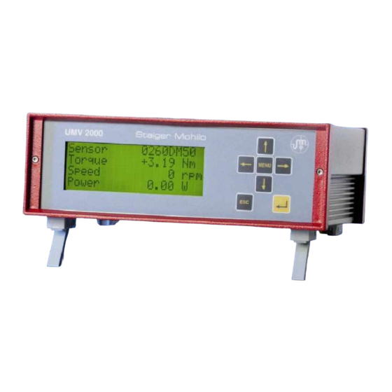
Page 6: Front And Rear View Of The Umv 2000
10/100 BASE-T SENSOR Please pay attention to the model plate of the UMV 2000. An alternation of operating voltage from 230V 50-60 Hz to 115V 50-60 Hz and vice versa is achieved by reconfiguring a jumper in the UMV 2000. In that case, please contact Dr. Staiger, Mohilo’s sales personnel. -
Page 7: Menu Prompting In The Umv 2000
In order to obtain an overview of the different setting versions, the individual menu items are further explained in the following: For adjustments in the UMV 2000, the MENU-key on the housing front of the UMV 2000 is operated. After that, the following main menu is shown: 3 2.2) -
Page 8: Menu Structure
Dr. Staiger, Mohilo + Co GmbH 2.1 Menu structure Main menu Configuration Open Communication Language Password Measur Save Delete Sensor Alarm Trigger Analog output extReset Alarm 1 output 1 extReset 1 Alarm 2 output 2 extReset 2 Measuring mode MENU Additional functions Reset Min/Max Trigger enable... -
Page 9: The Measuring Mode
P o w e r 0 . 0 2.3 Menu configuration In the ‘configuration’ menu all significant settings for the UMV 2000 are performed, concerning connections, quantity assessments (alarms), and triggered value storage (trigger). There are the following options: S e n s o r 2.2.1) -
Page 10: Submenu Sensor
Dr. Staiger, Mohilo + Co GmbH 2.3.1 Submenu sensor In the ’sensor’ menu, the UMV 2000 is programmed through a connected torque sensor or load cell. Assignments between output voltage / -frequency and applied rated torque or rated force of a sensor, are adjusted in this menu. -
Page 11: Configuring Output Signals Of A Sensor In The Umv 2000
Dr. Staiger, Mohilo + Co GmbH 2.3.1.1 Configuring output signals of a sensor in the UMV 2000 In ’Sign.Kind’ under a) you can select between ’Bridge’ , ’+/-5V’ , ’+/-10V’ and ’Freq.’. In this menu item the operator chooses a passive or active sensor. In this case, a passive sensor is a strain-gauge equipped version in bridge-configuration without an own amplifier. - Page 12 Two-range sensor e.g. 0260 DM Note A two-range sensor is integrated in the UMV 2000 by defining a nominal range (1:1) for the 1. range in c.1), and by defining an extended, i.e. smaller measuring range for the 2. range in c.2). The respective nominal values are indicated in d.1) and d.2). For each range it is possible to indicate own decimal positions in e.1) and e.2).
-
Page 13: Additional Display (Peak Value Storage, Low-Pass Filter Setting)
In the ’...min ’ and ’...max ’-options, the continuously operating min.-max.-storages are uploaded and displayed for the selected quantity. The limit frequency of a low-pass filter can be defined in the submenu ‘low-pass filter’ in the measuring mode. The power is calculated in the UMV 2000 as follows: ⋅ ω... -
Page 14: Alarm Function
Dr. Staiger, Mohilo + Co GmbH For the selected quantity under j) ’Add.Displ’ the corresponding unit can be assigned under k) ’Unit’, a calculation and presentation with correct values will result. torque: ’kNm’ ’Nm’ ’Ncm’ ’Nmm’ force: ’kN’ ’N’ speed: ’rpm’... -
Page 15: Quantities To Be Monitored
’LogicIn’ in g) defines whether alarm enable or alarm reset should be performed during the transition from ’0à1’ or ’1à0’. For assignments between analog voltage quantities and digital conditions please refer to chapter “technical specifications of the UMV 2000“. Example: ’0à1’ means that the alarm monitoring is enabled or reset in position ’1’. - Page 16 Note The high-resistive state (z) is caused by the open-collector outputs. If at each digital output an extern pull-up resistor R is added, 1-state instead of z-state is achieved. See the following diagram: UMV 2000 UMV 2000 OUTx OUTx state: z à...
- Page 17 Dr. Staiger, Mohilo + Co GmbH The illustration below presents an example of switching a digital output OUTx with ’LogicOut’ ’0àz’ using an extern pull-up resistor and defined hysteresis. M/F/n/a/P Threshold Lo Hysteresis Hysteresis Threshold Hi OUTx OUTx page 17 / 69 Operation manual no.
-
Page 18: Submenu Trigger
Dr. Staiger, Mohilo + Co GmbH 2.3.3 Submenu trigger The measured values are stored in the UMV 2000 in a so-called ring buffer in real time. Each storage location in the ring buffer contains a value package (time stamp, torque/force, speed/angle of rotation and calculated mechanic power). -
Page 19: Pre-, Middle-, And Post-Trigger
Dr. Staiger, Mohilo + Co GmbH The structure of the submenu ’trigger’ in the UMV 2000 is presented as follows: 4 M o d e p o s t 3 S o u r c e T o r T h r e s h . -
Page 20: Trigger Sources
’Button’ a key of the UMV 2000 activates the triggering. (’trigger enable’ in the auxiliary menu, please refer to chapter “Additional options“). Please note that possibly not all sources can be defined. If for example no torque measurement has been enabled in the sensor configuration, the selection ’Spe’... -
Page 21: Storage Time And Number Of Value Packages To Be Stored
For further details please refer to chapter “Additional options“à “Submenu trigger enable / trigger start”. The saved value packages can be read out by the UMV 2000 through the RS-232 interface via ASCII commands. Further details are explained in the chapters “Data logging software and interface commands”. -
Page 22: Configuration Example
In a motor test stand the speed- and torque sequence of a loaded motor should be recorded ( motor acceleration curve). The UMV 2000 is used as measuring and recording device. The digital input IN1 of the UMV 2000 serves as trigger input and a defined status change from 1 è... -
Page 23: Submenu Analog Output
2.3.4 Submenu analog output Any measured value (analog or frequency based signals) can be reproduced at analog outputs in scaled form. The UMV 2000 having the function of an amplifier. The calculated mechanic power can be provided as analog output signal as well. - Page 24 Dr. Staiger, Mohilo + Co GmbH In b) ’Min/...’ and in c) ’Max/...’ a scaling of the input value is effected. The output voltage value is scaled in d) ’OutMin/...’ and in e) ’OutMax/...’. The assignment of units (e.g. ’Min/Nm’) is effected automatically according to the settings in the sensor configuration.
-
Page 25: Resetting Of Peak Value Storage And Angle Value Through Digital Inputs
Dr. Staiger, Mohilo + Co GmbH 2.3.5 Resetting of peak value storage and angle value through digital inputs The UMV 2000 contains min.-/max. memories for each measured and calculated value (e.g. mechanic power), which are continuously updated in the background during the measurement. These memories can be reset either in the auxiliary menu ‘reset min/max’... -
Page 26: Opening A Parameter Set
UMV 2000. Standard setting is the parameter set ‘DEFAULT’, in which factory settings are filed. This parameter set cannot be deleted in the menu of the UMV 2000 and it cannot be overwritten. The designation of the loaded parameter set is displayed in the first line of the measuring mode. -
Page 27: Communication Menu
Dr. Staiger, Mohilo + Co GmbH 2.7 Communication menu The communication menu contains the RS-232- and Ethernet 10/100-Base-T-interface parameters. 4 P r o t o c o l S C P I 3 B a u d r a t e 1 1 5 2 0 0 E n d c h a r . -
Page 28: Ethernet-Interface
Ø 8 data bits Ø 1 stop bit Ø no parity. 2.7.2 Ethernet-interface The TCP/IP-settings in the UMV 2000 under d) to h) can only be applied in-house, and serve for software update. 2.8 Menu language Here you can select the menu languages ’english’... -
Page 29: Menu Function Password
‘change Password’. Consequently, a sensor configuration and overwriting of a parameter set is only possible if the password or the master password has been entered under ‘Password’ . In case of correct input, the password protection is inactive until the UMV 2000 is switched off again. There are four different password versions: User-defined password An order of max. -
Page 30: Additional Options
‘Hold’, and in ‘Enable’ the option ‘Button’ have been selected, 2.10.3 Additional options Additional submenus can be executed in the UMV 2000 by operating the return key ↵ during an operating measurement in the measuring mode. The following menu structure is shown: R e s e t M i n / M a x 2.9.1) -
Page 31: Resetting Other Peak Value Memories
The saved value packages can be uploaded by the UMV 2000 through the RS-232 interface with ASCII commands. Corresponding details are explained in the chapters “Data logging software” and “Interface commands”. -
Page 32: Switching Measuring Range
The measuring mode is accessed again by operating the ESC - key. In the measuring mode 'Sensor *' is displayed, if the extended measuring range has been selected. In the power-on condition of the UMV 2000, a changeover to the 1. measuring range (nominal range) is principally performed. -
Page 33: Taring Of The Zero Point
° Zero Adjust (taring) Note The zero offset is cancelled once the UMV 2000 is switched off and back on. However, should this taring be saved in non-volatile mode, this may be effected by saving the parameter set. Should the zero offset be cancelled this may be achieved by loading the ‘DEFAULT’... -
Page 34: Activating A Control Signal
Pin 23 +2,5V Ground reference at Pin 14 Assignments between analog voltage quantities and digital conditions are explained in chapter “Technical specifications of the UMV 2000“. page 34 / 69 Operation manual no. 1509 Maierhofstrasse 35 D – 73547 Lorch 1509e / 05.11.2004 / MHe... -
Page 35: Defining Of Low-Pass Filter
Dr. Staiger, Mohilo + Co GmbH 2.10.3.6 Defining of low-pass filter With the submenu ‘Low-pass Filter’ it is possible to define a software-low-pass filter of first order. A filter frequency can be assigned for the torque or force signal and, if defined in the sensor configuration, for the speed signal. -
Page 36: Service-Functions
The digital outputs (OUT8...OUT1) can be set or deleted directly through ’DOut’ i) . The 'service’-menu is removed from the main menu when the UMV 2000 is turned off and on. page 36 / 69 Operation manual no. -
Page 37: Connections On The Instrument Rear Panel
Dr. Staiger, Mohilo + Co GmbH 3. CONNECTIONS ON THE INSTRUMENT REAR PANEL Sensor socket of the UMV 2000 (SENSOR) and plug assignments of Staiger- Mohilo-sensors: UMV 2000 Staiger-Mohilo-sensors 0160 Specification Direction 0143 0143 25 pol. DSUB S 0160 0260... - Page 38 Dr. Staiger, Mohilo + Co GmbH ANALOG OUT: 9 pol. DSUB female Description Output 1 + N.C. N.C. N.C. Output 2 + Output 1 - N.C. N.C. Output 2 - Note: ’Output 1 –’ and ’Output 2 –’ are electrically connected in the inside. DIGITAL IN/OUT: 25 pol.
- Page 39 Dr. Staiger, Mohilo + Co GmbH RS-232-interface (RS-232): 9 pol. DSUB male Specification N.C. N.C. N.C. N.C. Ethernet-interface (10/100 BASE-T): RJ45 Specification TX + TX - RX + N.C. N.C. RX - N.C. N.C. page 39 / 69 Operation manual no. 1509 Maierhofstrasse 35 D –...
-
Page 40: Technical Specifications Of The Umv 2000
Fuses in the device socket: 230V/50-60Hz: 2x200mA T/5x20mm 115V/50-60Hz: 2x400mA T/5x20mm* « The range 115V AC 50-60Hz is only permitted if a jumper is reconfigured in the UMV 2000! Should you plan an operating voltage alternation please contact Dr. Staiger, Mohilo. DMS-input... - Page 41 Dr. Staiger, Mohilo + Co GmbH Quadrature-input (counter 1 and 2) Input resistance 10 kOhm Measuring range +/- 2 000 000 000 Sampling rate 1000 Hz Status 1 > 3.5 V Status 0 < 0.8 V Analog output Number Accuracy class (largest individual error) 0,1% Analog output +/-10 V, loadable with 1mA...
- Page 42 Dr. Staiger, Mohilo + Co GmbH Keys Number Sensor supplies Sensor supply 1 +/-12V max. 200mA Sensor supply 2 24V max. 500mA Supply of angle electronics, etc. 5V max. 100mA Sensor bridge supply 5V max. 100mA Extension port for intern option board Number of TTL outputs Number of TTL inputs Number of analog inputs...
-
Page 43: Data Logging Software
In connection with a UMV 2000, the program UMV 2000 Measurement Terminal allows you to measure, display and save values with your PC. Communication between the UMV 2000 and a computer is effected through the serial RS-232 interface. This program serves as demonstration for the communication mode of the UMV 2000. Easy commands are transmitted through the serial interface, in order to obtain instantaneous values. -
Page 44: System Requirements And Installation
“Auto Play“, the installation routine is shown automatically on your screen. Follow the instructions on the screen. After the installation has successfully been completed, a linkage to the UMV 2000 Measurement Terminal can be found in your start menu. - Page 45 Dr. Staiger, Mohilo + Co GmbH Fig.: Error message at the start of the program in case of missing or corrupted INI-file page 45 / 69 Operation manual no. 1509 Maierhofstrasse 35 D – 73547 Lorch 1509e / 05.11.2004 / MHe Tel.: 0 71 72 / 184-0 Fax: 0 71 72 / 184-500...
-
Page 46: The Main Window
Dr. Staiger, Mohilo + Co GmbH 5.3 The main window Immediately after the start of the program UMV 2000 - Measurement Terminal you access the main window. Here you can set the communication parameters, define the value file to be saved, effect measuring adjustments and select the quantities to be measured. -
Page 47: Language Setting
Dr. Staiger, Mohilo + Co GmbH 5.4 Language setting In the menu optionsàlanguages you can select the preferred language for the program. Any designations and texts (except special error messages and content of the value file) are adjusted to the language setting.. -
Page 48: Interface Settings
Dr. Staiger, Mohilo + Co GmbH 5.5 Interface settings In order to create a successful communication between the UMV 2000 and your computer the RS-232 parameters must be configured in Optionsàinterface settings. COM-Port The COM-port represents the serial RS-232 interface of your computer Baudrate This term defines the transmission rate of the serial RS-232 interface. - Page 49 (Baudrate) and the termination of the interface setting window. In order to test the interface settings connect the UMV 2000 through a 9-pole zero modem cable with your computer and switch it on. Please make sure that the communication settings in the UMV 2000 are correct.
-
Page 50: Defining A New File
6 Defining a new file In order to save measured values from the UMV 2000 with your computer, you must define a new file before storage is started. This file will later contain a table with your measured values. A file can be defined either with FileàNew... -
Page 51: Measuring Rate And Storage Time
From those the number of measured values to be stored from the UMV 2000 on the computer is determined. Should you plan to display measured values only, the measuring rate is critical. For storage of measured values the storage time is also important. -
Page 52: Measuring Quantities And Display
Please select only measuring quantities which are permitted in the actual measuring Note quantity configuration of the UMV 2000. If for example a speed measurement is active, an angle measurement with the program is not recommended. Furthermore, a mechanic power measurement can only be performed, if this functionality is enabled in the UMV 2000. -
Page 53: Performing Measurements And Presenting Measured Values On The Monitor
Note ü the RS-232-parametes comply with the ones in the UMV 2000, ü the UMV 2000 is connected with a zero modem cable and switched on, ü the correspondingly valid measuring quantities were selected in the program. Should you note temporal dropouts (measured values temporarily frozen) during measurement presentation, perform the following modifications: ü... -
Page 54: Storage Of Values
In the menu under MeasurementàStoringàStart or by operating the button Start storing you can start the storage of real-time values from the UMV 2000 through the RS-232-interface. The program saves all incoming measured values in the static memory of your computer and transfers these values in the previously defined file, when the storage is ended. - Page 55 Dr. Staiger, Mohilo + Co GmbH When all value positions have been assigned to a measuring quantity, a measuring sequence is started as represented in the following illustration: A time stamp (current time, resolved in 100µs) always belongs to the first measured value . After a short break the next measured value for the second value position is picked up, etc.
-
Page 56: Uploading The Ring Buffer
Dr. Staiger, Mohilo + Co GmbH 5.11 Uploading the ring buffer With OptionsàReading ring buffer the ring buffer contents of the UMV 2000 can be transferred through the serial RS-232 interface from the UMV 2000 to the computer. By operating Optionsà Reading ring buffer a configuration window is first shown, as in the following illustration Fig.: Configuration window for reading the UMV 2000 –... - Page 57 ü the UMV 2000 is connected with a zero modem cable, and switched on, ü a storage of measured values was effected in the UMV 2000 after a trigger operation. With the button Close the configuration window Reading ring buffer ... is closed and you return to the main window.
-
Page 58: Table Of Values
5.12 Table of values The value packages remaining in the RAM memory of the computer after a storage operation or after uploading the UMV 2000 – ring buffer can be presented numerically in the main window menu with Windowà Table of values . -
Page 59: Contents Of The Value File
Dr. Staiger, Mohilo + Co GmbH 5.13 Contents of the value file After a storage the measured values are transmitted to a value file. The name of the value file ends with TXT. The contents of this file are only ASCII characters, which can be read by conventional text ©... -
Page 60: Example For A Characteristic Measurement Of A Motor In Brake Operation
5.14 Example for a characteristic measurement of a motor in brake operation With a UMV 2000 and the UMV 2000-measurement terminal – program the torque and speed sequences of a motor specimen are measured, on which a brake operation is performed during operation. - Page 61 Dr. Staiger, Mohilo + Co GmbH A section of the torque- and mech. power sequence with dependence on speed can be seen in the © © following illustration. For instructions on Microsoft Excel please refer to your Excel -user’s manual. Fig.: Torque and mech.
-
Page 62: Interface Commands
Dr. Staiger, Mohilo + Co GmbH 6. Interface commands Through the RS-232-interface a communication between the UMV 2000 and an operator PC is possible. The ASCII commands to be used are based on SCPI-standards (standard commands for programmable instruments), to allow a simple and understandable communication. -
Page 63: Command Trace
= <number of value packages>, whereby Description: With this command it is possible to reset min.-/max-storages in the UMV 2000. In addition, the contents of the UMV 2000 – ring buffer may be uploaded. Uploading of the ring buffer makes sense, if a triggering has previously been activated in the UMV, and a number of measured values have been intermittently stored in the ring buffer. - Page 64 If several packages are requested at the same time (e.g. TRACe:BUFFer 0,1000?) the UMV 2000 transmits them as a connected ASCII data string. In order to avoid extremely long data strings,...
-
Page 65: Command *Esr
Dr. Staiger, Mohilo + Co GmbH 6.4 Command *ESR *ESR? Description: The *ESR?-command (Event Status Register Query) displays the contents of the 8-bit register as decimal (0..255) and deletes it subsequently. The following configuration of the ESR-register: ESR-Register event Gewichtung value Assignment: 1 = event bit is set... -
Page 66: Command *Opc
To allow a bus operation, a RS 485 converter must be connected at the RS-232 interface of the UMV 2000 and a RS-485 bus must be realized. RTS- and CTS-leads are available at the RS-232-socket of the UMV 2000 (see chapter “Technical specifications of the UMV 2000“. -
Page 67: Command Select
Note The command INP:GAIN:MULT-command actually represents a valid command of a two- range sensor from Dr. Staiger, Mohilo. The UMV 2000 transfers this command directly to the sensor. After the changeover a confirmation with “0” results. page 67 / 69 Operation manual no. -
Page 68: Index
Dr. Staiger, Mohilo + Co GmbH 7 Index *ESR?............... 65 german language..........47 *IDN? ............... 62 *OPC? .............. 66 high-resistive condition (z)........ 16 Hysteresis ............15 Add.Displ ............13 address.............. 66 INI file (Software) ..........44 Address............. 28 addressing UMV ..........66 INP:GAIN:MULT .......... - Page 69 Dr. Staiger, Mohilo + Co GmbH Sign.Kind ............11 Storage of values (software)....... 54 storing period ............ 21 storing time............21 switching range..........32 TCP/IP .............. 28 reading ring buffer (commands) ......63 termination............48 Reset Min/Max (other) ........31 Thr.Hi ...............
Need help?
Do you have a question about the UMV 2000 and is the answer not in the manual?
Questions and answers