Table of Contents
Advertisement
Quick Links
Advertisement
Table of Contents

Summary of Contents for neuroConn DC-Stimulator
- Page 1 Programmable Direct Current Stimulator DC- STIMULATOR User manual...
-
Page 5: Table Of Contents
......................Equipment ......................Consumables ......................Type label ........................ Power supply ........................ Activating the DC-STIMULATOR ........................ Mode standby ........................ Turning off the DC-STIMULATOR ........................ Operating Basics ........................External charger ........................ Electrodes ........................ Cleaning and storing ......................Impedance control ........................ Additional hardware ........................ - Page 6 Table of contents PARAMETER ........................ tDCS ......................STIMULATION ........................ SYSTEM ........................ Trigger input (optional) ......................Impedance limit ......................Load setting ......................Study mode (optional) ......................Procedure ....................... Language set ......................Signal tone ......................Backlight brightness ......................MASTERCODE (optional) ........................ Troubleshooting ........................
- Page 7 Table of contents Electrode paste Ten20 ........................
-
Page 8: Preface
• a predefined stimulation time will not be exceeded (max. tolerance (1%) This manual shows you how to operate the DC-STIMULATOR. The devices of the neuroConn GmbH are delivered with user manuals in English or German language (Germany, Austria and Switzerland) depending on the destination country. - Page 9 This informs the user that failure to follow these instructions may cause harm to the user and others or may damage the DC-STIMULATOR or other equipment. This is a general hint or useful advice for better use of the DC-STIMULATOR.
-
Page 10: Safety
Investigational Device. Federal (or US) law limits this device to investigational use. The construction of the DC-STIMULATOR conforms to the regulations set out in the Medical Device Directive 93/42/EEC (Date of issue 14th June 1993), which was put into German law. The requirements of the following standard(s) or normative document(s) are... -
Page 11: Important Notes
Modifications and repair of the DC-STIMULATOR must be carried out only by the manufacturer or a company authorized by the manufacturer. The DC-STIMULATOR must never be opened. The manufacturer assumes no responsibility for any damage caused by such a practice. - Page 12 Chapter 2 - Safety The DC-STIMULATOR must not be used in combination with a defibrillator as it has no appropriate protection. The manufacturer accepts no responsibility for any injury caused by such use. The DC-STIMULATOR must not be used on patients with a pacemaker or brain stimulator as such use can interfere or damage these devices.
- Page 13 Chapter 2 - Safety The output circuit of the constant current source of the DC-STIMULATOR is equipped with an electrical fuse which limits the current to 5 mA. Therefore, in any faulty condition and during normal operation, the fuse will become open circuit if the current exceeds 5 mA by a significant amount.
-
Page 14: Safety Aspects Of Transcranial Direct Current Stimulation (Tdcs)
Chapter 2 - Safety Safety aspects of transcranial Direct Current Stimulation (tDCS) Attention! - In following situations the patient might be injured! Only place the electrodes on healthy skin. If there are known allergies you should consult a general practitioner or dermatologist first. Never use it with injured skin areas. -
Page 15: Safe Stop Mode
Chapter 2 - Safety Histological limit for the duration of DC current applications To avoid permanent injury of tissue, duration of DC current applications should be temporary. The charge per surface area should not exceed a value of 216 C/cm². E.g.: Using electrodes with a surface area of 35 cm²... -
Page 16: Getting Started
Chapter 3 - Getting Started Getting Started General conditions Before using the DC-STIMULATOR, please read the following advice to make sure a proper environment is provided: - The room temperature should be between 10 and 40 °C (50 and 104 °F) and the air humidity should be between 20 and 93 % (non condensing). -
Page 17: Dc-Stimulator
Chapter 3 - Getting Started DC-STIMULATOR DC-STIMULATOR upside Figure 1: Upside of DC-STIMULATOR DC-STIMULATOR bottom side Figure 2: Bottom side of the DC-STIMULATOR... - Page 18 Chapter 3 - Getting Started DC-STIMULATOR front side Figure 3: Front side of the DC-STIMULATOR Label/ Specifications icon Pay attention! It is necessary to note the manual's instructions for this socket! applied part BF refer to instruction manual (ISO 7010-M0002)
- Page 19 "4" (signal) for touch-proofed safety connectors ø 2 mm to connect the adapter box TRIGGER IN DC-STIMULATOR rear side Figure 4: Rear side of the DC-STIMULATOR The patient must not touch the contacts at the rear side of the device.
-
Page 20: Equipment
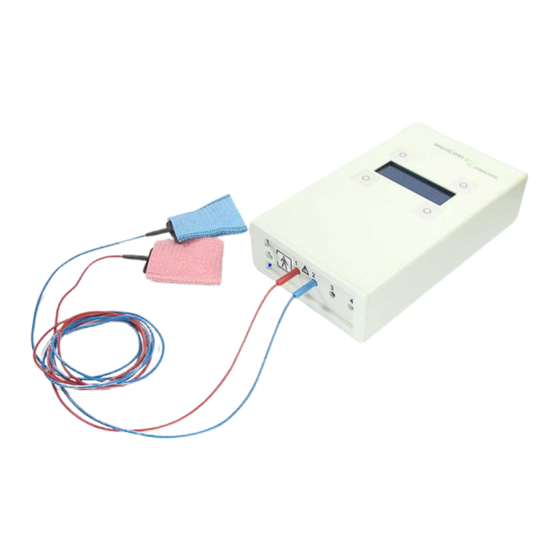
Chapter 3 - Getting Started Equipment Adapter box TRIGGER IN This adapter box is a module for connecting external trigger sources to the DC- STIMULATOR. It consists of the following components: 1 adapter box 2 BNC socket 3 touch-protected connecting cable ø 2 mm to plug in into socket 4 (signal) of the DC- STIMULATOR 4 touch-protected connecting cable ø... - Page 21 Chapter 3 - Getting Started Figure 6: Starter set of the DC-STIMULATOR 1 rubber electrodes, 1 pair 2 sponge pads for the rubber electrodes, 1 pair, red-blue 3 rubber strap combination for fixing the rubber electrodes on the head, 1 set 4 connection cables, approx.
-
Page 22: Type Label
Chapter 3 - Getting Started Type label The type label of the DC-STIMULATOR consists of the elements shown in Figure 7. Figure 7: Type label of the DC-STIMULATOR manufacturer, address and production year serial number applied part BF Mind the manual! -
Page 23: Power Supply
On the edge of the type label the STK sticker (inspection plate Technical Safety Inspection) for the next safety check up will be added. The next check up is determined by neuroConn's STK policy (24 months, MTK 12 months) and added by a hole using a ticket punch. - Page 24 For safety reasons, charging the batteries is possible only when no electrodes are connected. The front plate of the DC-STIMULATOR can be moved so that either the electrodes or the external charger may be connected. Never try to plug in both at the same time.
-
Page 25: Activating The Dc-Stimulator
Figure 8: Activating the DC-STIMULATOR Mode standby If the DC-STIMULATOR is not used over a longer period of time, it switches automatically to standby mode in order to save energy. After 30 seconds of inactivity the display turns dark. Additionally, an acoustic warning signal (beep) reminds you every 60 seconds of inactivity that the device is still switched on. - Page 26 Chapter 3 - Getting Started Figure 9: Turning off the DC-STIMULATOR...
-
Page 27: Operating Basics
Chapter 4 - Operating Basics Operating Basics External charger The DC-STIMULATOR front plate can be moved because of the necessary change between the two operating modes “Charge” and “Stimulation” (see Figure 10 and Figure 11). Figure 10: Front plate in "Charge" position Figure 11: Pushing into "Stimulation"... -
Page 28: External Charger
Chapter 4 - Operating Basics External charger While the front plate is in the “Charge” position, the DC-STIMULATOR can be charged according to the following instructions: - Plug the charger into the appropriate DC-STIMULATOR socket (see Figure 14 and Figure 15). -
Page 29: Electrodes
- When charging is finished (LED lights green) take the external charger out of the DC- STIMULATOR and the live outlet. You can leave the charger plugged in even if the DC-STIMULATOR is fully charged. There is no risk of damaging the DC-STIMULATOR. -
Page 30: Cleaning And Storing
Chapter 4 - Operating Basics The electrodes therefore need to provide the following conditions to keep the current density low: - sufficient surface area, - low impedance, i.e. appropriate material and good skin contact. Furthermore, the electrode material must be resistant to electrochemical processes that occur during long term DC currents, especially for metal-to-body reactions at the transition from skin to electrode. -
Page 31: Impedance Control
5 minutes before the new measurement. Impedance control Before beginning stimulation, the DC-STIMULATOR will detect the impedance levels. A DC current of 120 µA is used for several milliseconds. If impedance is above the adjusted level, e.g. - Page 32 Chapter 4 - Operating Basics Please also note the relationship between electrode impedance and maximum stimulation current, shown in Figure 17. NB: Impedance warnings also appear if voltage limitation of 22 V is reached or exceeded. For example, a current of 2 mA at 10 kOhm impedance produces a voltage drop of 20 V.
-
Page 33: Additional Hardware
For more details, please ask your dealer or the manufacturer. Trigger input To start stimulation remotely or via other devices, the DC-STIMULATOR can be used with an external trigger. The trigger mode can be adjusted by the software (see Software Reference Manual: Trigger input). -
Page 34: Cleaning The Device
The trigger level must last for a minimum of 1 ms. Cleaning the device Clean the DC-STIMULATOR using a cloth slightly dampened with water. For the display a standard commercial TFT display cleaner should be used. Spray some cleaner on a soft and clean cloth before wiping the display gently. -
Page 35: Moving The Device
Chapter 4 - Operating Basics Moving the device Switch off the DC-STIMULATOR and disconnect all connecting cables. Usually, the DC- STIMULATOR comes in a plastic shipping case cushioned with foam, thus ensuring safe and reliable shipment. Room temperature should be between 10 and 40 °C (50 and 104 °F) and the air humidity should be between 20 to 93 % (non condensing). - Page 36 Chapter 4 - Operating Basics Pay attention on the correct positions of the single components and make sure that the optical fiber cable of the AMPLIFIER never gets folded. Additionally used pictogram's and warning signs to the packaging: This side up Fragile Handle with care Keep dry...
-
Page 37: Storing The Device
Chapter 4 - Operating Basics Storing the device If the DC-STIMULATOR is not used for a while, it is recommended that it is stored in a safe, dry and dust-free place. The temperature must be between 10 and 40 °C (50 and 104 °F) and the air humidity must be between 20 and 93 % (non condensing). -
Page 38: Software Reference Manual
Display, button, menu The DC-STIMULATOR is operated by using the 4 buttons near the display's corner (see Figure 19). In the whole Software Reference Manual the numbering of the buttons shown in Figure 19 is used. - Page 39 DC-STIMULATOR is used further (see Manual: External charger for details). A blank loudspeaker symbol indicates that the signal tone of the DC-STIMULATOR (for warnings and notices) is not active. After activating the signal tone (see Software Reference Manual: Signal tone) the symbol is filled white.
-
Page 40: Parameter
Chapter 5 - Software Reference Manual PARAMETER This menu offers the selection of stimulation waveform modes and the associated parameters like current, duration etc.. The chosen parameters can be saved into configurations (setting A - D) by pushing button 1 and 3 simultaneously. -
Page 41: Stimulation
Chapter 5 - Software Reference Manual total stimulation time = fade in + duration + fade out Figure 21: Timing chart of current during tDCS The following table summarizes the available parameters for stimulation waveform mode tDCS: minimum value increment maximum value unit current... - Page 42 Chapter 5 - Software Reference Manual Figure 22: Main menu STIMULATION Line 3 of the display shows all stimulation parameters set by the user. Press button 1 to start the stimulation. Then the system performs an impedance check (Figure 23), measuring the electrode impedance between electrode and skin.
-
Page 43: System
Chapter 5 - Software Reference Manual Figure 24: Display during stimulation Terminating the stimulation The ongoing stimulation can be terminated by the user at any time by pressing button 1 (x). The display indicates: “Stimulation terminated by user!”. The menu then returns to the main menu PARAMETER. -
Page 44: Trigger Input (Optional)
Chapter 5 - Software Reference Manual Trigger input (optional) To start stimulation remotely or via other devices, the DC-STIMULATOR can be used with an external trigger. For technical details please see Manual Operation Basics: Trigger input. Trigger input can be: disabled (Standard) Trigger input is disabled. -
Page 45: Impedance Limit
- Press button 1 several times to move the cursor back to line 1 (the main menu). The trigger input is disabled automatically when you turn your DC-STIMULATOR off. However, you can save the set of trigger input in the setting. -
Page 46: Load Setting
"save setting A" (depending on choice B, C or D). Figure 27: Main menu SYSTEM, submenau load setting The stimulation parameters defined in the settings still remain active after rebooting the DC-STIMULATOR. Switching on the DC-STIMULATOR always setting A (in study mode setting B) is the active setting. -
Page 47: Study Mode (Optional)
Chapter 5 - Software Reference Manual Study mode (optional) The study mode was designed to facilitate the performance of double-blind comparative studies on the effectiveness of transcranial electric stimulation. 200 5-digit codes are available in the manual which are used to switch between “normal” and “sham” stimulation in double-blind conditions. - Page 48 Chapter 5 - Software Reference Manual Codes for normal stimulation 23613 35947 17155 39147 03229 37424 45931 63064 49185 48496 28303 41567 52627 05497 61961 60027 39451 16617 57242 33646 48014 27671 63004 04722 36268 19135 56227 22004 44577 03502 23373 32656 28471...
-
Page 49: Procedure
Chapter 5 - Software Reference Manual Timing chart of current - sham stimulation Figure 29: Timing chart of current during sham stimulation (tDCS) duration Example: = 8 s; = 5 s; = 900 s fade in fade out duration Stimulation starts with 8 s fade in followed by 30 s direct current followed by 5 s fade out followed by 870 s without any stimulation (just impedance control). - Page 50 - Press button 1 several times to move the cursor back to line 1 (the main menu). After enabling the study mode you have to reboot the DC-STIMULATOR (switch off and switch on the device). Without reboot the study mode will not work correctly.
-
Page 51: Language Set
Chapter 5 - Software Reference Manual Completing the study To finish the study switch the DC-STIMULATOR on. The display will immediately switch to limited selection of settings (Figure 30). Press button 2 and enter the mastercode as described in Software Reference Manual: MASTERCODE. -
Page 52: Signal Tone
- when you set implausible stimulation parameters - when you enable / disable the study mode - when the DC-STIMULATOR is switched on and not used for more than one minute The speaker symbol in the third line informs you about the current status of the signal tone. -
Page 53: Mastercode (Optional)
- Press button 1 several times to move the cursor back to line 1 (the main menu). Figure 34: Main menu SYSTEM, submenu backlight brightness NB: Backlight brightness is an important factor of the DC-STIMULATOR operating time, since backlight needs, at maximum, 30 % of the power consumption. - Page 54 Chapter 5 - Software Reference Manual To enter the MASTERCODE press button 2 in the settings selection in active study mode. Then follow these instructions: - The cursor is located in the first digit (see Figure 35). Press button 1 to increase the value by 1 per press.
-
Page 55: Troubleshooting
Chapter 6 - Troubleshooting Troubleshooting If any further assistance is required, or if any problems are experienced during DC-STIMULATOR use, please contact your dealer or the manufacturer. Hotline: - Tel. +49 (0) 3677 68 979 0 - Fax. +49 (0) 3677 68 979 15... -
Page 56: Technical Specifications
Chapter 7 - Technical Specifications Technical Specifications Essential performance - a maximum output current of 2 mA (tDCS) will not be exceeded (max. tolerance 5%) - a predefined stimulation time will not be exceeded (max. tolerance (1%) General - 135 mm x 225 mm x 55 mm (W x D x H), weight 0.8 kg - power consumption approx. - Page 57 Chapter 7 - Technical Specifications - voltage limit max. ±22 V The device's DC offset is between +/-10 µA without stimulation after an operating time of 5 min at the time of delivery. This offset can increase up to +/-20 µA during normal operation.
-
Page 58: Electromagnetic Compatibility
Chapter 8 - Electromagnetic compatibility Electromagnetic compatibility To ensure the safe operation of your device or system, be sure to observe the operating manual for your device or system, the information in the chapter "Safety" and the following additional guidelines and safety precautions. The device or system complies with the EMC requirements of the international standard IEC 60601-1-2:2001 and is suitable for use in an environment with a medical application. -
Page 59: Guidance And Manufacturer's Declaration - Electromagnetic Emissions
Chapter 8 - Electromagnetic compatibility Guidance and manufacturer's declaration - electromagnetic emissions The device or system is intended for use in the electromagnetic environment specified below. The customer or the user of the device or system should assure that it is used in such an environment. - Page 60 Chapter 8 - Electromagnetic compatibility Immunity test IEC 60601 test Compliance Electromagnetic environment - level level guidance Electrostatic discharge ±6 kV (contact) passed, B Floors should be wood concrete or IEC 61000-4-2 ±8 kV (air) ceramic tile. If floors are covered with synthetic material the relative humidity should be at least 30 %.
- Page 61 Chapter 8 - Electromagnetic compatibility Immunity test IEC 60601 test Compliance Electromagnetic environment - level level guidance calculated from the equation applicable to the frequency of the transmitter. Recommended separation distance: d=[3.5/E ]sqrt(P) 80 to 800 MHz Radiated RF 0.08-1; 1.4-2; passed, A IEC 61000-4-3 2-2.7 GHz...
-
Page 62: Recommended Separation Distances Between Portable And Mobile Rf Communication Equipment And The Device Or System
"operator/use" action. This means for the user of the neuroConn system: if voltage dips, short interruptions and voltage variations on power supply input lines occured the user has to turn off and turn on the device. - Page 63 Chapter 8 - Electromagnetic compatibility Rated maximum Separation distance according to frequency of transmitter [m] output power of 150 kHz to 80 MHz 80 MHz to 800 MHz 800 MHz to 2.5 GHz transmitter d=[3.5/3]sqrt(P) d=[3.5/3]sqrt(P) d=[7/3]sqrt(P) 0.01 not applicable not applicable not applicable not applicable...
-
Page 64: Service
Chapter 9 - Service Service Warranty The DC-STIMULATOR is covered by a 12 month warranty worldwide and a 24 month warranty within the European Union. Maintenance The DC-STIMULATOR should be maintained every 12 months. According to the german medical products law a technical safety inspection has to be done every 24 month (only in Germany). -
Page 65: Safety Inspection
• check whether the accuracy limits are complied 4. safety control • according to the appropriate content of the EN 62353:2008 5. final acceptance test (FAT) as specified by the neuroConn GmbH Please contact the manufacturer for detailed information to carry out the final acceptance test. -
Page 66: Distributors
Chapter 10 - Distributors Distributors Germany, Austria, Switzerland neuroConn GmbH Albert-Einstein-Str. 3 98693 Ilmenau Germany Tel.: (+49) 03677 68979 0 Fax: (+49) 03677 68979 15 E-Mail: info@neuroconn.de Web: www.neuroconn.de International Rogue Resolutions Sophia House 28 Cathedral Road Cardiff CF11 9LJ Great Britain Tel.: (+44) 2920 660198... - Page 67 Chapter 10 - Distributors We have additional or exclusive distributors in the countries listed below: Australia, New Zealand, Oceania Symbiotic Devices Ltd. Pty Suite 138, 245 Thomas Street VIC 3175 Dandenong, Australia Tel.: (+44) 2920 660198 E-Mail: info@symbioticdevices.com.au Web: www.symbioticdevices.com.au Benelux (Belgium / The Netherlands / Luxembourg) MedCaT B.V.
- Page 68 Chapter 10 - Distributors Canada Rogue Research Inc. 206-4398 Boul. St-Laurent Montreal Quebec, H2W 1Z5, Canada Tel.: (+1) 514 284 3888 Toll Free (North America): 1 866 984 3888 E-Mail: info@rogue-research.com Web: www.rogue-research.com China Rogue Resolutions Sophia House 28 Cathedral Road Cardiff CF11 9LJ, Great Britain Tel.: (+44) 2920 660198 E-Mail: info@rogue-resolutions.com...
- Page 69 Chapter 10 - Distributors Hongkong Largro Ltd. Unit 809, Sun Fung Centre 88 Kwok Shui Road, Tsuen Wan, Hongkong Tel.: (+852) 2418 2198 Fax: (+852) 2426 2968 E-Mail: enquiry@largro.com Web: www.largro.com India Sigma Technolgies 55, Periyar Nagar Uppilaipalaym Post Varadharajapuram 641015 Coimbatore, India Tel.: (+91) 952718737 E-Mail: info@sigmatech.co.in...
- Page 70 Chapter 10 - Distributors Iran Sepehr HTM Solutions Co. Unit. 305 No. 2244 Negin Tower, Vliasr St. 1968635391 Teheran, Iran Tel.: (+98) 21 8870 2196 E-Mail: info@sepehrhtm.com Japan Miyuki Giken Co., Ltd. Hongo Diya Bldg., 6F 3-18-14 Hongo, Bunkyoku Tokyo 113-0033, Japan Tel.: (+81) 3 3818 8631 Fax: (+81) 3 3818 6832 E-Mail: miyuki@miyuki-net.co.jp...
- Page 71 Chapter 10 - Distributors Spain ALMEVAN, S.L.U. Poligono Industrial La Mina Norte C/Madroño, nº6, nave 33 28700 Colmenar Viejo (Madrid), Spain Tel.: (+34) 91 659 11 60 Fax: (+34) 91 651 52 12 E-Mail: ruben.sanz@almevan.com Web: www.almevan.com Taiwan, R. O. C. Trushine Medical Instruments Co., Ltd.
- Page 72 Chapter 10 - Distributors Turkey Binas Med. Sistemler Sa. ve Tic. Ltd. Sti. Medelek Elektronic ve Bilgisayar Cihazlari Perpa Ticaret Merkezi, A Blok, 9. Kat, San. ve Tic. Ltd. Sti. No: 1195-97 Darül Aceze Cad. No: 47 34384 Istanbul Famas Is Merk. Kat:1 Turkey 34384 Istanbul Turkey...
-
Page 73: Intended Use And Therapeutic Application
Chapter 11 - Intended use and therapeutic application Intended use and therapeutic application Since the beginning of the 19th century efforts have been made to achieve therapeutic effects with the help of electricity, but the level of knowledge was not high enough. The growing knowledge in the field of neurophysiology during the last two decades enabled huge development steps of this type of therapy. - Page 74 Chapter 11 - Intended use and therapeutic application Patient population age group: 18 - 99 years weight: 45 - 120 kg nationality: global patient state: conscious adult patients disabilities: not relevant excluded patient types: patients with opened skull, after trepanation or with heart resp. brain pacemaker patients with any skin damage further criteria:...
- Page 75 Chapter 11 - Intended use and therapeutic application experience: • experience in brain stimulation • knowledge of the current state of technology and of the textbook "Interventionelle Neurophysiologie", mainly the therapy chapters (see [1]) permitted disabilities: none Intended conditions of use Use in clinics, practicing doctors and psychologists Indications The transcranial direct current stimulation can be used in the treatment of the following...
- Page 76 Chapter 11 - Intended use and therapeutic application In a clinical trial treating patients suffering from depression: • rare cases of euphoria, hypomania, nausea, disorientation, anxiety, and insomnia No specific risks due to the treatment are known. Burns can occur if other liquids than saline solution are used to wet the electrodes. Overview of the therapeutic recommendations for tDCS for adults [3] Neuropathic pain in Probable analgesic effect of anodal tDCS of M1 of the left...
- Page 77 Chapter 11 - Intended use and therapeutic application Depression probable antidepressant effects of anodal tDCS of the left Level B DLPFC with right orbiotofrontal cathode in depressed patients without treatment resistance (support of the therapy). • tDCS • anodal • duration: 30 minutes •...
- Page 78 Chapter 11 - Intended use and therapeutic application Motor stroke No recommendation for cathodal tDCS of contralesional M1 or anodal tDCS of ipsilesional M1. Depression No recommendation for cathode location over the right DLPFC. No recommendation for associated cognitive symptoms. Multiple sclerosis No recommendation for anodal tDCS of M1 or the left DLPFC for motor or sensory disorders, including pain...
-
Page 79: Disclaimer
This manual has been validated and reviewed for accuracy. The manual is accurate for the DC-STIMULATOR at the time of this manual’s production. Changes to the DC-STIMULATOR are possible at any time according to the latest research and development in science and technology. -
Page 80: Notes
Chapter 13 - Notes Notes... -
Page 81: Manuals Equipment
Manuals Equipment The following pages show manuals of some equipment and consumables of the DC-STIMULATOR. These manuals refer to the DC-STIMULATOR equipped with all options and consumables. Depending on the specification of your DC- STIMULATOR some of the equipment/consumables might not be available. - Page 82 Chapter 14 - Manuals Equipment Electrode paste Ten20...
- Page 83 Index Index - I - impedance check - A - impedance control 31, 41 manual acclimatization impedance limit adverse reactions adjust application therapeutic indications intended use - B - - L - backlight brightness language set batteries capacity - M - charging main menu buttons...
- Page 84 Index requirements safety notes troubleshooting transcranial direct current stimulation - U - safety inspection user profile service setting - V - loading voltage limitation sham stimulation current timing chart - W - shipment warranty signal tone changing sponge cleaning storing wetting stimulation completing...
- Page 85 Publisher neuroConn GmbH Albert-Einstein-Str. 3 98693 Ilmenau Fon +49 - 36 77 - 68 979 0 Fax +49 - 36 77 - 68 979 15 E-Mail: info@neuroconn.de Internet: www.neuroconn.de...
Need help?
Do you have a question about the DC-Stimulator and is the answer not in the manual?
Questions and answers