Advertisement
Advertisement
Table of Contents

Summary of Contents for XSY AT Series
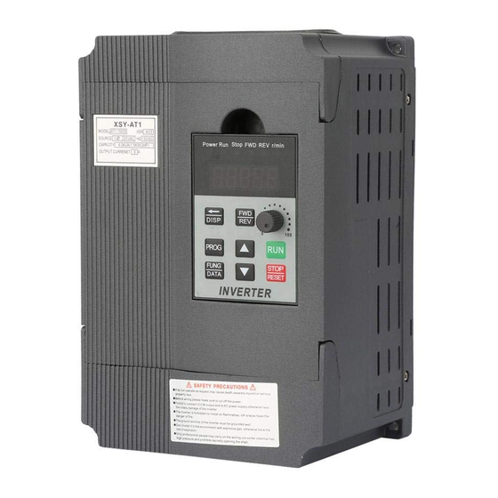
- Page 1 Inverter AT1--Single-phase to three-phase AT2--Single-phase to single-phase AT3--Three-phase to three-phase AT Simple general series High performance and low noise/ Mini AC motor driver...
-
Page 2: Table Of Contents
Contents Chapter 1 Introduction ....1 Chapter 2 Installation and wiring...2 Port wiring and instructions....2 Multi speed frequency comparison table..Basic wiring diagram ....... Operation panel......Button instructions......Button instructions......Chapter 3 Parameter specification..10 Parameter function comparison table... 10 Down timer setting.... -
Page 3: Chapter 1 Introduction
Chapter 1 Introduction This manual is for user installation and debugging and routine maintenance. 1. Make the open-package inspection. Please check: if product appearance is damaged or deformation; whether the components are damaged or drop; check the nameplate rating on the case to see if it is your order; check whether the times listed in the packing list are complete;... -
Page 4: Chapter 2 Installation And Wiring
Charter 2 Installation and wiring 1. Main circuit terminal and function description (1) Single-phase to three-phase (for AT1) Terminal Function description label L, N Single phase AC 220V input terminal Output terminal connect to Three phase U, V, W 220V AC motor 220V AC motor Grounding terminal (2) Single-phase input and output (for AT2) - Page 5 (3). Three-phase input and output (for AT3) Terminal Function description label R,S,T Three phase AC 380V input terminal Output terminal connect to Three phase U, V, W 380V AC motor Grounding terminal 2. Terminal description Functional Functional Port Instructions description 15V/24V 15V/24V power output 200mA15V/24V output...
-
Page 6: Multi Speed Frequency Comparison Table
Functional Port Instructions description Common GND External analog voltage 0-5V/10V Analog voltage input input External current signal 4-20mA Current input input Open-collector output 1 Open-collector output 2 5V/10V 5V/10V power output supply 5V/10V 20mA power output Relay output C 250VAC 5A/30VDC 3A Relay output B TA and TB Normal Close ,TA and TC Normal Open... -
Page 7: Basic Wiring Diagram
4. Basic operation wiring diagram (1) Single-phase input three-phase output (for AT1 ) (Three phase 220V, if 380V Star-connection method needs to change to the 220V Delta-connection method) 5页... - Page 8 (2). Single-phase input and output (for AT2) (220V single phase motor, Non-removed capacitor / Removed capacitor) 6页...
- Page 9 (3). Three-phase input and output (for AT3) (380V three phase input, connect with 380V three phase motor) 7页...
-
Page 10: Operation Panel
5. Operation panel 8页... -
Page 11: Button Instructions
6. Keys instructions: Icon Function description For selecting mode or Programming mode (it is (Programming) available not mater the Inverter start or stop), press this key for modifying parameters. Function data setting key. Normal mode: press this key to display the information of the Inverter, (Function / Save) such as target frequency, output frequency and current, temperature;... -
Page 12: Chapter 3 Parameter Specification
Chapter 3 Parameter specification 1. Parameter specification Paramet Parameter Parameter range Default Unit specification Maximum voltage 0---220.0 Reference frequency 0---400.0 Intermediate voltage 0---220.0 Intermediate 0---400.0 frequency Minimum voltage 0---220.0 Minimum frequency 0---400.0 Maximum operating Maximum operating 0---400.0 0---400.0 Minimum operating 0---400.0 Hide password 0---65535... - Page 13 0: Inertial stop; 1: Deceleration stop; Stopping Modes 2: Brake stop; 3: Emergency brake. Braking time 0---2.5 Braked Voltage 0---140.0 RS485format 0:7E1; 1:701; 2:8N2; 3:8E1; ASCII 4:801. 0: 4800; 1:9600; RS485 Baud rate 2:19200; 3:38400 Machine number 1-255 Operating arrival 0---100.0 Persist Over temperature...
- Page 14 Section speed 1 setting 0---400.0 Section speed 2 setting 0---400.0 Section speed 3 setting 0---400.0 Section speed 4 setting 0---400.0 Section speed 5 setting 0---400.0 Section speed 6 setting 0---400.0 Section speed 7 setting 0---400.0 Main rising velocity 1---1000 Hz/S 1st rising velocity 1---1000 Hz/S...
- Page 15 1---1000 Hz/S 6th descent velocity 1---1000 Hz/S 7th descent velocity 0: invalid, terminal is non- functioning 1: wire control stop 2: keying stop; 3: keying operation; 4: stop keying; 5: wire forward operation 6: wire reverse operation; 7: reservation P50 Multi function input 1 (X1 binding post) 8: error reset signal;...
- Page 16 0: invalid, no output; 1: operating instructions; 2: set arrival instructions Multi function input 1 3: fault indication; 4: timer time run out Idem (SP1) Multi function input 2 Idem Multi function input 3 Idem (relay output) Multi function input 4 0: invalid;...
- Page 17 0: P72 is compensation amount; Torque compensation 1: Multiply P72 by P71 options after P71 minus input voltage Torque compensation 100.0---300.0 voltage Torque compensation 0---100 setting Maximum external 61440 analog 0---65535 Minimum external 4096 analog 0---65535 Zero current 0-65535 1130 compensation value Current coefficient Current coefficient...
- Page 18 Jog forward frequency 0---400.0 Jog reverse frequency 0---400.0 Jog rising velocity 1---1000 Hz/S Jog descent velocity 1---1000 Hz/S 0: Inertia stop; 1: Decelerate stopp; Jog stopping modes 2: Braking stop; 3: Emergency brake. Jog braking time 0---2.5 0:Three-phase Phase options 2:Three-line single phase Phase V Adjustment...
-
Page 19: Down Timer Setting
P115 PID-I Coefficient P116 PID-D Coefficient P127 0---65535 65535 Remaining hours 2. Parameter setting password and Down time stop: P08 is the hidden password, it always shows only 00000, not the actual value. When input the value of P09=the hidden value of P08, the P08 shows hidden value, and the P08 and other parameters can be changed. -
Page 20: Parameter Setting Method
4. Parameter setting procedure: 1. Press the programming key to enter into the programming state; 2. Use the arrow keys and shift key to find the parameters that need to be modified; 3. Press function / save key to enter into the parameter; 4. - Page 21 Parameter Checklist Customer :______Purpose :______Model:______ : Remark 19页...
-
Page 22: Chapter 5 Quality Commitment
Chapter 5 Quality Commitment This chapter introduces the “Quality Commitment” and if there are any problems about the product quality, our company will deal with in accordance with the following regulations, please read the contents in this chapter carefully. The quality commitment regulations of the product: Scope of warranty: refers to Inverter Start of warranty period: from the date of operated by users Warranty commitment:...
Need help?
Do you have a question about the AT Series and is the answer not in the manual?
Questions and answers
что такое защита от пониженного напряжения, где искать?
как устранить эрор 2
Error 2 on the XSY AT Series indicates an "Undervoltage protection" fault. To fix this issue:
1. Check the power supply voltage to ensure it meets the required specifications.
2. Inspect wiring connections for loose or damaged cables.
3. Verify that the power input terminals are properly connected.
4. If the voltage is too low, consider using a stable power source or voltage regulator.
5. Restart the inverter after correcting any voltage issues.
If the problem persists, further troubleshooting or professional assistance may be needed.
This answer is automatically generated
@Aleks a que se refiere el error 1? Ya resete el módulo y la falla aún persiste.
error 8 como solucionar?
Error 8 on the XSY AT Series indicates "Excessive temperatures for radiator." To fix this error:
1. Check if the cooling fan is working properly.
2. Ensure the radiator is clean and not blocked by dust or debris.
3. Improve ventilation around the inverter.
4. Reduce the load or allow the inverter to cool down before restarting.
After resolving the issue, restart the inverter to clear the error.
This answer is automatically generated
At5-1500x 110v single phase input to 220v 3phase output model. Cannot change parameters. Can't unlock the password. Is there a hard reset configuration or what can I do to fix this issue??
To unlock the password and change parameters on the XSY AT Series AT5-1500X, follow these steps:
1. Locate Parameter P08: This is the hidden password parameter. It always displays as "00000" and does not show the actual stored value.
2. Enter the Password Using P09:
- Set parameter P09 to the hidden value of P08 (you must know the correct password value).
- If correct, P08 will then reveal the hidden value, and parameter changes will be allowed.
3. Change Parameters: Once unlocked, you can modify P08 and other parameters.
4. Power Cycle Effect:
- If you unplug the power cable and restart, P09 will be cleared.
- You would need to re-enter the correct value into P09 again to unlock parameters.
A hard reset method is not described. If the password is unknown, there is no documented way to bypass or reset it without the correct value.
This answer is automatically generated
@Mr. Anderson thank you for the input. I've tried all the above but cannot get it to unlock. I'm going to try some more but if not able to change the parameters. Possibly buy another vfd