
Related Manuals for Thornhill Medical MOVES SLC

Summary of Contents for Thornhill Medical MOVES SLC
- Page 1 Operator’s Manual Caution: Federal law restricts this device to sale by or on the order of a physician. © 2016 Thornhill Research Inc. All Rights Reserved Part Number: 124826 Rev. J 20 April 2020...
- Page 2 THIS PAGE DELIBERATELY LEFT BLANK...
-
Page 3: Table Of Contents
SLC™ Operator’s Manual ® Thornhill Research Inc. MOVES Table of Contents 1.0 Notices ..................................1 Contact Information ............................1 1.1.1 Manufacturer ............................1 1.1.2 Notified Body ............................1 1.1.3 Authorized Representatives ........................ 1 Patent Notice ..............................1 Copyright Notice ............................1 Trademark Notices ............................ - Page 4 SLC™ Operator’s Manual ® MOVES Thornhill Research Inc. 6.1.1 Notes, Cautions and Warnings ......................35 6.1.2 Operational Symbols ........................36 6.1.3 Label Warning Symbols ........................36 6.1.4 Product Labels Symbols ........................36 General Warnings ............................39 Electrical Warnings ............................. 41 Patient-Specific Warnings ..........................
- Page 5 SLC™ Operator’s Manual ® Thornhill Research Inc. MOVES 7.5.13 General Description for Carboxyhemoglobin (SpCO) ..............63 7.5.14 Successful Monitoring for SpCO ....................63 7.5.15 General Description for Methemoglobin (SpMet) ................. 63 7.5.16 Successful Monitoring for SpMet ....................63 7.5.17 SpCO, SpMet, and SpHb Measurements During Patient Motion ..........64 8.0 Troubleshooting the Masimo Pulse Oximeter ......................
- Page 6 SLC™ Operator’s Manual ® MOVES Thornhill Research Inc. SLC™ to the Power Supply / Battery Charger ........138 ® 9.13.6 Connecting MOVES 9.13.7 Connecting AC Power ........................ 139 9.13.8 Battery Storage ........................... 139 10.0 Startup .................................. 141 10.1 Adjusting the Screen Display Orientation ....................141 10.2 User Interface (UI) Controls and Functions ....................
- Page 7 SLC™ Operator’s Manual ® Thornhill Research Inc. MOVES 11.6.5 Actual PEEP Higher than Set PEEP ................... 184 11.6.6 Inverted Display of Patient Monitoring Values ................184 11.6.7 Invasive Pressure (IP) Source Buttons ..................185 11.6.8 Zeroing a Channel........................185 11.7 ECG Screen ..............................
- Page 8 SLC™ Operator’s Manual ® MOVES Thornhill Research Inc. 14.2 Available System Graphs / Trends ......................232 14.2.1 System Graphs ........................... 232 14.2.2 System Trends..........................234 15.0 Alarms .................................. 237 15.1 About Status LEDs ........................... 237 15.2 Alarm Priorities and Characteristics ......................237 15.2.1 Standard Alarms .........................
- Page 9 SLC™ Operator’s Manual ® Thornhill Research Inc. MOVES 16.7.3 Airflow Monitoring Specifications ....................318 16.7.4 Monitoring Specifications ....................319 16.7.5 Respiratory Rate Monitoring Specifications ................319 16.7.6 Monitoring Specifications ....................... 320 16.7.7 ECG Specifications ........................320 16.7.8 NIBP Specifications........................323 16.7.9 Invasive Pressure Specifications ....................
- Page 10 SLC™ Operator’s Manual ® MOVES Thornhill Research Inc. List of Tables Table 1: Quick Reference to Information on Procedures ....................17 Table 2: Glossary of Terms and Abbreviations ....................... 21 Table 3: Regulatory Symbols Used and Description ...................... 25 Table 4: Regulatory Standards Compliance ........................25 Table 5: Symbols and Messages Used in Manual ......................
- Page 11 SLC™ Operator’s Manual ® Thornhill Research Inc. MOVES SLC™ ....................... 307 ® Table 45: Physical Properties of MOVES SLC™ in a Circle Circuit ..........309 ® Table 46: Oxygen Concentrator Specifications of MOVES SLC™ in O2 Supplement Mode ........309 ®...
- Page 12 SLC™ Operator’s Manual ® MOVES Thornhill Research Inc. Table of Figures Figure 2-1: Battery Verify Test Screen ..........................16 SLC™ Upright System Orientation and Components ..............28 ® Figure 5-1: MOVES Figure 7-1: Absorption Spectra of Blood Components ....................61 Figure 7-2: LEDs and Detector ............................
- Page 13 SLC™ Operator’s Manual ® Thornhill Research Inc. MOVES Figure 11-22: Regular Temperature Display ........................ 185 Figure 11-23: Inverted Display of Temperature (Alarm Condition) ................185 Figure 11-24: ECG Screen – Normal Mode ......................... 186 Figure 11-25: ECG Screen – Graphs Paused ......................186 Figure 11-26: Alarm Limits Screen –...
-
Page 15: Notices
SLC™ Operator’s Manual ® Thornhill Research Inc. MOVES Notices CONTACT INFORMATION 1.1.1 Manufacturer Address: Thornhill Research Inc. 60 Wingold Ave Toronto, Ontario Canada M6B 1P5 Phone: +1.416.597.1325 Website: http://www.thornhillmedical.com 1.1.2 Notified Body British Standards Institute Netherlands Number 2797 BSI Group The Netherlands B.V. -
Page 16: Trademark Notices
SLC™ Operator’s Manual ® MOVES Thornhill Research Inc. TRADEMARK NOTICES ® MOVES is a registered trademark of Thornhill Research Inc. SLC™ is a trademark of Thornhill Research Inc. All brand and product names mentioned herein are used for identification purposes only and are trademarks or registered trademarks of their respective holders. -
Page 17: Declaration Of Conformity Notice
SLC™ Operator’s Manual ® Thornhill Research Inc. MOVES 1.10 DECLARATION OF CONFORMITY NOTICE ® SLC™ is declared to conform to the Medical Device Directive of the European community (re: Medical MOVES Device Directive 93/42/EEC). This is indicated by the CE Mark shown below. ®... - Page 18 SLC™ Operator’s Manual ® MOVES Thornhill Research Inc. THIS PAGE DELIBERATELY LEFT BLANK.
-
Page 19: Moves ® Slc™ Quick Start Guide For Ventilated Patients
SLC™ Operator’s Manual ® Thornhill Research Inc. MOVES MOVES SLC™ Quick Start Guide for Ventilated ® Patients Equipment Setup Procedures ® SLC™. Insert the 1. Lift the release/lock latch for the ventilator cartridge door at the top front of the MOVES ventilator cartridge, close the door and lock it by depressing the latch. - Page 20 SLC™ Operator’s Manual ® MOVES Thornhill Research Inc. Attach the water trap to the “from patient” port on the ventilator cartridge door. Attach the ventilator breathing circuit patient hoses to the water trap and “to patient” port on the ventilator cartridge door.. Connect the Nafion tubing to the sampling line.
- Page 21 SLC™ Operator’s Manual ® Thornhill Research Inc. MOVES ® ® SLC™ power supply/charger to MOVES SLC™ if batteries require charging and/or Connect the MOVES ® SLC™ is to be powered from wall power. MOVES NOTE: MOVES® SLC™ requires either two batteries to be installed, or one battery installed and connection to the power supply / charger and wall power, when in operation.
- Page 22 SLC™ Operator’s Manual ® MOVES Thornhill Research Inc. 11. Follow the on-screen instructions to complete the System Tests. When all tests have been completed and passed, select CONTINUE. Optional: Further details regarding the System Tests can be found in Section 2.1 System Test Instructions on page 10.
- Page 23 SLC™ Operator’s Manual ® Thornhill Research Inc. MOVES Changing the Ventilator Cartridge During Operation SLC™ advises the operator to change the ventilator cartridge: ® If MOVES • Remove a new cartridge from packaging prior to making any changes to the system. •...
-
Page 24: System Test Instructions
SLC™ Operator’s Manual ® MOVES Thornhill Research Inc. SYSTEM TEST INSTRUCTIONS 1. The System Test screen is displayed. NOTE: The Jog Wheel control is used to select options. It moves from selection to selection in a circular clockwise or counterclockwise direction around the screen depending on the direction it is turned. - Page 25 SLC™ Operator’s Manual ® Thornhill Research Inc. MOVES 3. Perform the preparation steps indicated if the test is PREP REQD (for other tests that are INPUT REQD, respond with the input requested), then choose Prep done to run the test. NOTE: In order to save time, certain tests can be run concurrently.
- Page 26 SLC™ Operator’s Manual ® MOVES Thornhill Research Inc. 4. The closed Y-Piece test is completed and passed in the screen shot at the right. To initiate the Alarm Lights + Audio tests, user input is required. Start must be confirmed, and then the operator must continue to observe the device and answer the questions shown on the device.
- Page 27 SLC™ Operator’s Manual ® Thornhill Research Inc. MOVES 6. The second Alarm Lights & Audio test also requires input from the user (INPUT REQD test). This test ensures that the medium-priority alarm visual indicator is working properly. Respond with Yes or No. 7.
- Page 28 SLC™ Operator’s Manual ® MOVES Thornhill Research Inc. 8. As noted previously, in order to save time, certain tests can be run concurrently. In this case, while the Open Y-Piece test is still running, the Sample Line tests can be run. 9.
- Page 29 SLC™ Operator’s Manual ® Thornhill Research Inc. MOVES Test 2 of 2 10. When testing is in progress, and the ® SLC™ is running, a small MOVES white dot can be seen moving up and down at the top right of the screen to indicate that the device is not “frozen”.
-
Page 30: Figure 2-1: Battery Verify Test Screen
SLC™ Operator’s Manual ® MOVES Thornhill Research Inc. BATTERY VERIFY TEST SCREEN ® If the MOVES SLC™ is connected to wall power, or has two full batteries, the Battery Verify test will be passed automatically and its test screen will not appear in the startup sequence. However, if neither of these two conditions is satisfied, the Battery Verify test screen will appear. -
Page 31: Further Information On Procedures
SLC™ Operator’s Manual ® Thornhill Research Inc. MOVES FURTHER INFORMATION ON PROCEDURES For further information on procedures, see the sections indicated in the following table. Table 1: Quick Reference to Information on Procedures PROCEDURE Page 1. Attaching the shoulder strap. ®... - Page 32 SLC™ Operator’s Manual ® MOVES Thornhill Research Inc. PROCEDURE Page 22. Viewing graphs and trends of patient data. 23. Taking NIBP readings manually. 24. Using the remote screen. ® SLC™. 25. Shutting down MOVES...
- Page 33 SLC™ Operator’s Manual ® Thornhill Research Inc. MOVES THIS PAGE DELIBERATELY LEFT BLANK.
-
Page 35: Introduction
SLC™ Operator’s Manual ® Thornhill Research Inc. MOVES Introduction ® This Operator’s Manual is a reference guide for the MOVES SLC™ mobile life support system (P/N 122752). This manual includes illustrations, annotated photographs and procedures designed to assist in the operation of various systems, subsystems and components that comprise the unit. - Page 36 SLC™ Operator’s Manual ® MOVES Thornhill Research Inc. TERM / DEFINITION ABBREVIATION Fraction of Inspired Oxygen by Volume (%) Functional Residual Capacity – the volume of air (about 3 liters in an adult) that is present in the lungs at the end of a normal expiration. Fresh Gas Gas which has a negligible concentration of CO Frequency...
-
Page 37: Moves ® Slc™ Intended Use
SLC™ Operator’s Manual ® Thornhill Research Inc. MOVES TERM / DEFINITION ABBREVIATION Pleth Variability Index PVI may help clinicians non-invasively assess the fluid status of a patient. Respiratory Rate. Breaths per minute (B/M). Safe Gas Mode SpCO Saturation percentage of carbon monoxide attached to hemoglobin. CO (carbon monoxide) competes with oxygen for the oxygen-binding sites on hemoglobin. -
Page 38: Operating Environment
SLC™ Operator’s Manual ® MOVES Thornhill Research Inc. a. Suction ® SLC™ suction pump is intended for aspiration and removal of fluids, tissue (including bone), gases, The MOVES bodily fluids or infectious materials from wounds or from a patient's airway or respiratory support system. b. -
Page 39: Regulatory Compliance
SLC™ Operator’s Manual ® Thornhill Research Inc. MOVES Regulatory Compliance REGULATORY SYMBOLS ® SLC™ unit, power supply and battery charger, Regulatory symbols have been added to the labeling on the MOVES and accompanying accessories to indicate regulatory compliance. These symbols, along with a brief description, are shown in the following table. - Page 40 SLC™ Operator’s Manual ® MOVES Thornhill Research Inc. STANDARD # DESCRIPTION IEC/EN 60601-1 Medical Electrical Equipment (Ed 3.0, 2005), General Requirements for basic safety and essential performance. Medical Electrical Equipment – Part 1-2: General requirements for safety – Collateral standard: IEC 60601-1-2 Electromagnetic compatibility –...
-
Page 41: Moves Slc™ System Overview
SLC™ Operator’s Manual ® Thornhill Research Inc. MOVES MOVES SLC™ System Overview ® GENERAL OVERVIEW ® SLC™ system is comprised of six main modules: The MOVES 1. Oxygen Concentrator 2. Ventilator 3. Suction System 4. Patient Monitoring System 5. Disposable breathing cartridges and breathing circuits for intubated patients 6. -
Page 42: Theory Of Operation
SLC™ Operator’s Manual ® MOVES Thornhill Research Inc. ® Figure 5-1: MOVES SLC™ Upright System Orientation and Components THEORY OF OPERATION 5.3.1 Breathing Circuit and Oxygen Supplement Intubated patients are ventilated with a circle circuit (called a ventilator circuit) used with a ventilator cartridge. Oxygen and air enter the circuit from either the oxygen concentrator, the air pump or an external O supply. -
Page 43: Oxygen Concentrator
SLC™ Operator’s Manual ® Thornhill Research Inc. MOVES 5.3.2 Oxygen Concentrator The concentrator provides up to or greater than 87% O into the ventilator breathing circuit during Ventilate mode or directly to the O outlet during O2 Supplement mode. 5.3.3 Ventilator The ventilator is comprised of a blower, a sealed ventilator chamber that houses the ventilator bag (air / oxygen reservoir), and a valve block that interfaces with the breathing cartridge and ventilator breathing circuit. - Page 44 SLC™ Operator’s Manual ® MOVES Thornhill Research Inc. WARNING! DO NOT REUSE SAMPLING LINES OR FILTERS. THIS COULD PRESENT A DANGER OF INFECTION. ® SLC™ NOTE: Compensation for barometric pressure and temperature is performed by MOVES ® SLC™ internal sensing equipment to maintain accuracy of gas calibration over the MOVES ®...
-
Page 45: Suction
SLC™ Operator’s Manual ® Thornhill Research Inc. MOVES ADVERSE EFFECTS ® SLC™ respiratory gas monitoring in itself. However, There are no known adverse effects associated with MOVES sampling lines and filters are not reusable and could present a danger of infection were they to be reused. They should be disposed of in accordance with local biohazard regulations. -
Page 46: Power System
SLC™ Operator’s Manual ® MOVES Thornhill Research Inc. sensor, incorrect sensor type, poor pulse quality, venous pulsations, anemia or low hemoglobin concentrations, cardiogreen or other intravascular dyes, carboxyhemoglobin, methemoglobin, dysfunctional hemoglobin, artificial nails or fingernail polish, or a sensor not at heart level. The pulse oximeter is calibrated by the original manufacturer to display functional oxygen concentration. -
Page 47: System Auto Resume On Power Loss
SLC™ Operator’s Manual ® Thornhill Research Inc. MOVES NOTE: The battery charge level may not appear to increase for approximately 3 hours. This is normal for the battery's initial charge and after extended periods without use. 5.3.8 System Auto Resume on Power Loss If the system has been shut down for a period of time less than or equal to three (3) minutes, the system will auto resume using the system settings configuration prior to shutdown. - Page 48 SLC™ Operator’s Manual ® MOVES Thornhill Research Inc. THIS PAGE DELIBERATELY LEFT BLANK...
-
Page 49: Safety Information
SLC™ Operator’s Manual ® Thornhill Research Inc. MOVES Safety Information MANUAL SYMBOLS AND MESSAGES 6.1.1 Notes, Cautions and Warnings This manual contains important messages with symbols labeled NOTE, CAUTION and WARNING. These messages have the following format and meaning: Table 5: Symbols and Messages Used in Manual Supplies additional information that will help complete, offer an alternative to, or explain a portion of a given procedure. -
Page 50: Operational Symbols
SLC™ Operator’s Manual ® MOVES Thornhill Research Inc. 6.1.2 Operational Symbols Table 6: Operational Symbols and Descriptions SYMBOL DESCRIPTION Single Phase Alternating Current Direct Current 6.1.3 Label Warning Symbols Table 7: Label Warning Symbols and Descriptions SYMBOL DESCRIPTION Fire Hazard: Do not smoke near unit. Fire Hazard: Do not operate device near open flame. - Page 51 SLC™ Operator’s Manual ® Thornhill Research Inc. MOVES SYMBOL DESCRIPTION Do not reuse (single use only) No latex used in the manufacture of this product Power indicator Battery indicator Class II equipment Authorized Representative in the European Community Manufacturer Date of manufacture Date of expiration (use by) Lot number Reference or Model Number...
- Page 52 SLC™ Operator’s Manual ® MOVES Thornhill Research Inc. SYMBOL DESCRIPTION E-mail The equipment shall not be disposed of as unsorted municipal waste and shall be collected as electrical and electronic equipment, as applicable, separately as specified by Waste Electrical and Electronic Equipment (WEEE). Battery condition indicator Non sterile;...
-
Page 53: General Warnings
SLC™ Operator’s Manual ® Thornhill Research Inc. MOVES SYMBOL DESCRIPTION Protect from rain Do not expose to sunlight Read usage instructions GENERAL WARNINGS Table 9: General Warnings SYMBOL GENERAL WARNING ® SLC™ SHOULD NOT BE USED WITH INHALED ANESTHETICS. WARNING! THE MOVES ®... - Page 54 SLC™ Operator’s Manual ® MOVES Thornhill Research Inc. SYMBOL GENERAL WARNING ® SLC™ SHOULD NOT BE USED IN A HYPERBARIC CHAMBER. WARNING! THE MOVES WARNING! THE OPERATOR SHOULD ALWAYS HAVE AVAILABLE AN ALTERNATE MEANS OF SUCTION IN THE EVENT OF POWER FAILURE, MECHANICAL FAILURE OR SERIOUS OCCLUSION IN THE SUCTION CIRCUIT.
-
Page 55: Electrical Warnings
SLC™ Operator’s Manual ® Thornhill Research Inc. MOVES SYMBOL GENERAL WARNING ® SLC™ CONTAINS AN OXYGEN CONCENTRATOR, IT WARNING! BECAUSE THE MOVES SHOULD ONLY BE USED IN A WELL-VENTILATED ENVIRONMENT AWAY FROM POLLUTANTS, FLAMES, SPARKS, OR FUMES. WARNING! LEAKS IN THE SAMPLING LINE CAN CAUSE LOW PCO AND/OR LOW O LEVELS. - Page 56 SLC™ Operator’s Manual ® MOVES Thornhill Research Inc. SYMBOL ELECTRICAL WARNING WARNING! CONDUCTIVE PARTS OF ELECTRODES AND ASSOCIATED CONNECTORS FOR APPLIED PART, INCLUDING THE NEUTRAL ELECTRODE, SHOULD NOT CONTACT OTHER CONDUCTIVE PARTS AND EARTH. SOME RF EMITTERS (E.G. RFID) MAY NOT BE VISIBLE AND THE DEVICE CAN POTENTIALLY BE EXPOSED TO FIELDS FROM THESE RF EMITTERS WITHOUT THE USER’S AWARENESS.
-
Page 57: Patient-Specific Warnings
SLC™ Operator’s Manual ® Thornhill Research Inc. MOVES PATIENT-SPECIFIC WARNINGS Table 11: Patient-Specific Warnings SYMBOL PATIENT-SPECIFIC WARNINGS WARNING! IN THE EVENT OF DISAGREEMENT BETWEEN THE DEVICE AND THE REMOTE SCREEN THE DEVICE SHALL BE CONSIDERED CORRECT. WARNING! IF THE REMOTE SCREEN BECOMES INOPERABLE, LOCKS UP OR BEHAVES ERRATICALLY, IT SHOULD NO LONGER BE USED AND BE DISCONNECTED FROM THE SYSTEM. - Page 58 SLC™ Operator’s Manual ® MOVES Thornhill Research Inc. SYMBOL PATIENT-SPECIFIC WARNINGS WARNING! WHEN A BLOOD PRESSURE CUFF IS TO BE POSITIONED ON A PATIENT FOR AN EXTENDED LENGTH OF TIME, BE SURE TO OCCASIONALLY CHECK THE LIMB FOR PROPER CIRCULATION. WARNING! USING A BLOOD PRESSURE CUFF OVER A WOUND MAY CAUSE FURTHER INJURY.
-
Page 59: Masimo Rainbow Set Pulse Co-Oximeter Warnings
SLC™ Operator’s Manual ® Thornhill Research Inc. MOVES SYMBOL PATIENT-SPECIFIC WARNINGS WARNING! ALWAYS CARRY ALTERNATE MEANS OF VENTILATING, SUCTIONING, AND OXYGENATING THE PATIENT. WARNING! ALWAYS CARRY BACKUPS OF CONSUMABLES SUCH AS CARTRIDGES AND FILTERS. WARNING! DEFIBRILLATOR PROTECTION REQUIRES USE OF SPECIFIED ACCESSORIES, INCLUDING PATIENT CABLES AND TRANSDUCERS. - Page 60 SLC™ Operator’s Manual ® MOVES Thornhill Research Inc. ® SYMBOL MASIMO RAINBOW SET PULSE CO-OXIMETER WARNINGS WARNING! FOR MEASUREMENTS OF HIGH OR LOW SPHB READINGS, BLOOD SAMPLES SHOULD BE ANALYZED BY LABORATORY INSTRUMENTS TO COMPLETELY UNDERSTAND THE PATIENT’S CONDITION. WARNING! SPO IS EMPIRICALLY CALIBRATED TO FUNCTIONAL ARTERIAL OXYGEN SATURATION IN HEALTHY ADULT VOLUNTEERS WITH NORMAL LEVELS OF CARBOXYHEMOGLOBIN (COHB) AND METHEMOGLOBIN (METHB).
- Page 61 SLC™ Operator’s Manual ® Thornhill Research Inc. MOVES ® SYMBOL MASIMO RAINBOW SET PULSE CO-OXIMETER WARNINGS WARNING! VENOUS CONGESTION MAY CAUSE UNDER READING OF ACTUAL ARTERIAL OXYGEN SATURATION. THEREFORE, ASSURE PROPER VENOUS OUTFLOW FROM MONITORED SITE. SENSOR SHOULD NOT BE BELOW HEART LEVEL (E.G., SENSOR ON HAND OF A PATIENT IN A BED WITH ARM DANGLING TO THE FLOOR).
- Page 62 SLC™ Operator’s Manual ® MOVES Thornhill Research Inc. ® SYMBOL MASIMO RAINBOW SET PULSE CO-OXIMETER WARNINGS WARNING! DO NOT USE THE PULSE CO-OXIMETER OR OXIMETRY SENSORS DURING MAGNETIC RESONANCE IMAGING (MRI) SCANNING. INDUCED CURRENT COULD POTENTIALLY CAUSE BURNS. THE PULSE CO-OXIMETER MAY AFFECT THE MRI IMAGE, AND THE MRI UNIT MAY AFFECT THE ACCURACY OF THE OXIMETRY MEASUREMENTS.
-
Page 63: General Cautions
SLC™ Operator’s Manual ® Thornhill Research Inc. MOVES ® SYMBOL MASIMO RAINBOW SET PULSE CO-OXIMETER WARNINGS WARNING! USE ONLY MASIMO SENSORS FOR PULSE OXIMETRY OR PULSE CO-OXIMETRY MEASUREMENTS. WARNING! SPO SENSOR APPLICATION SITES SHOULD BE INSPECTED AT LEAST EVERY FOUR (4) HOURS, OR AS DIRECTED IN THE SENSOR'S DIRECTIONS FOR USE, TO ENSURE CORRECT SENSOR ALIGNMENT AND SKIN INTEGRITY. - Page 64 SLC™ Operator’s Manual ® MOVES Thornhill Research Inc. SYMBOL GENERAL CAUTION CAUTION! BEFORE INSTALLING A HYDROCARBON FILTER, CHECK THE FOUR-DIGIT DATE CODE PRINTED ON THE CARTRIDGE. THE CARTRIDGE LABEL IS STAMPED WITH FOUR CHARACTERS “XXYY”, WHERE “XX” IS THE WEEK OF THE YEAR AND “YY” IS THE YEAR. A CARTRIDGE MORE THAN THREE YEARS OLD SHOULD BE DISCARDED SINCE IT MAY ®...
- Page 65 SLC™ Operator’s Manual ® Thornhill Research Inc. MOVES SYMBOL GENERAL CAUTION CAUTION! THE LABEL ON THE PACKAGE OF THE VENTILATOR CARTRIDGE CONTAINS AN EXPIRY DATE. ALWAYS CHECK THE EXPIRY DATE ON THE VENTILATOR CARTRIDGE BEFORE USING IT TO MAKE SURE THAT THE VENTILATOR CARTRIDGE HAS NOT EXPIRED. AS WELL, MONITOR SPARE CARTRIDGES WITH REGARD TO THEIR REMAINING “SHELF LIFE”.
-
Page 66: Electrical Cautions
SLC™ Operator’s Manual ® MOVES Thornhill Research Inc. ELECTRICAL CAUTIONS Table 14: Electrical Cautions SYMBOL ELECTRICAL CAUTION ® SLC™ IS INTENDED FOR USE BY HEALTHCARE PROFESSIONALS ONLY. CAUTION! MOVES ® SLC™ MAY CAUSE RADIO INTERFERENCE OR MAY DISRUPT THE OPERATION OF MOVES NEARBY EQUIPMENT. - Page 67 SLC™ Operator’s Manual ® Thornhill Research Inc. MOVES ® SLC™ system must not be used for any purpose other than as stated in section 3.2 MOVES® 5. The MOVES SLC™ Intended Use on page 23 . ® SLC™ unit must always be used and stored in accordance with the environmental 6.
-
Page 68: Electrical Safety
SLC™ Operator’s Manual ® MOVES Thornhill Research Inc. 6.10 ELECTRICAL SAFETY ® SLC™ power supply / charger only to an AC source from 100–240V, 50–60 Hz, 1. Connect the MOVES ® 5.5 A max. Fluctuations in voltage and current can have adverse effects on the performance of the MOVES SLC™... -
Page 69: Radio Interference
SLC™ Operator’s Manual ® Thornhill Research Inc. MOVES 6.12 RADIO INTERFERENCE CAUTION! INTERFERENCE MAY OCCUR IN THE VICINITY OF KNOWN RADIO FREQUENCY (RF) TRANSMITTING DEVICES AND EQUIPMENT MARKED WITH THE FOLLOWING SYMBOL: 6.13 BATTERY HANDLING Please note the following important cautions regarding battery handling: •... -
Page 70: Suction
SLC™ Operator’s Manual ® MOVES Thornhill Research Inc. 6.15.2 Suction • Application of suction within defined accuracy requirements or generation of a technical alarm 6.15.3 80601-2-12 (General Ventilation) • Delivery of ventilation at the PATIENT-CONNECTION PORT within the ALARM LIMITS set by the OPERATOR or generation of an ALARM CONDITION 6.15.4 80601-2-13 (Anesthetic Ventilation) - Page 71 SLC™ Operator’s Manual ® Thornhill Research Inc. MOVES 6.15.9 80601-2-55 • MEASUREMENT ACCURACY and GAS READING ALARM CONDITION or generation of a TECHNICAL ALARM CONDITION 6.15.10 80601-2-61 • SpO2 ACCURACY, PULSE RATE ACCURACY and limit ALARM CONDITIONS or generation of a TECHNICAL ALARM CONDITION...
-
Page 73: The Masimo Rainbow Set Pulse Co-Oximeter
SLC™ Operator’s Manual ® Thornhill Research Inc. MOVES The Masimo Rainbow SET Pulse CO-Oximeter ® NO IMPLIED LICENSE Possession of this device does not convey any express or implied license to use the device with unauthorized sensors or cables that would, alone, or in combination with this device, fall within the scope of one or more of the patents relating to this device. -
Page 74: Pulse Oximeter Technology Overview
SLC™ Operator’s Manual ® MOVES Thornhill Research Inc. PULSE OXIMETER TECHNOLOGY OVERVIEW ® 7.5.1 Signal Extraction Technology (SET Masimo Signal Extraction Technology's signal processing differs from that of conventional pulse oximeters. Conventional pulse oximeters assume that arterial blood is the only blood moving (pulsating) in the measurement site. During patient motion, however, the venous blood also moves, causing conventional pulse oximeters to read low values, because they cannot distinguish between the arterial and venous blood movement (sometimes referred to as noise). -
Page 75: General Description For Pleth Variability Index (Pvi)
SLC™ Operator’s Manual ® Thornhill Research Inc. MOVES 7.5.7 General Description for Pleth Variability Index (PVI) The pleth variability index (PVI) is a measure of the dynamic changes in the perfusion index (PI) that occur during the respiratory cycle. The calculation is accomplished by measuring changes in the PI over a time interval where one or more complete respiratory cycles have occurred. -
Page 76: Pulse Co-Oximetry Vs. Drawn Whole Blood Measurements
SLC™ Operator’s Manual ® MOVES Thornhill Research Inc. 1. Light Emitting Diodes (LEDs) (7 + wavelengths) 2. Detector Figure 7-2: LEDs and Detector ® Once the Masimo Rainbow SET Pulse CO-Oximeter receives the signal from the sensor, it utilizes proprietary algorithms to calculate the patient’s functional oxygen saturation (SpO [%]), blood levels of carboxyhemoglobin (SpCO [%]), methemoglobin (SpMet [%]), total hemoglobin concentration (SpHb [g/dL]) and pulse rate (PR). -
Page 77: Successful Monitoring For Sphb
SLC™ Operator’s Manual ® Thornhill Research Inc. MOVES The sensor connects directly to the Pulse CO-Oximeter or with a patient cable. The sensor collects signal data from the patient and sends it to the instrument. The instrument displays the calculated data as measurement of total hemoglobin concentration. -
Page 78: Spco, Spmet, And Sphb Measurements During Patient Motion
SLC™ Operator’s Manual ® MOVES Thornhill Research Inc. 7.5.17 SpCO, SpMet, and SpHb Measurements During Patient Motion ® SLC™ displays measurements of SpCO, SpMet, and SpHb during patient motion. However, because The MOVES of the changes in the physiological parameters such as blood volume, arterial-venous coupling, etc., that occur during patient motion, the accuracy of such measurements may not be reliable during excessive motion. -
Page 79: Troubleshooting The Masimo Pulse Oximeter
SLC™ Operator’s Manual ® Thornhill Research Inc. MOVES Troubleshooting the Masimo Pulse Oximeter The following chapter contains information about troubleshooting the pulse oximeter. TROUBLESHOOTING MEASUREMENTS The operation of the Pulse Oximeter can be verified by using a function simulator such as the Fluke ProSim 8 Vital Signs Simulator with the ProSim RAINBOW test cable (#4034609). -
Page 80: Spo2 Values Do Not Correlate With Clinical Assessment Or Arterial Blood Gas Measurements
SLC™ Operator’s Manual ® MOVES Thornhill Research Inc. SPO2 VALUES DO NOT CORRELATE WITH CLINICAL ASSESSMENT OR ARTERIAL BLOOD GAS MEASUREMENTS Low perfusion or sensor displacement. Next steps: Check for pulse oximeter alarm messages. See Alarm Conditions and Causes beginning on page 246. Check placement of sensor or if it is too tight. -
Page 81: Getting Started
SLC™ Operator’s Manual ® Thornhill Research Inc. MOVES Getting Started The following section provides information and instructions on installing and connecting various parts and accessories ® SLC™ for activation. and preparing the MOVES CAUTION! THESE ACTIVITIES SHOULD BE CARRIED OUT ONLY BY AUTHORIZED / TRAINED PERSONNEL. -
Page 82: Moves ® Slc™ System Contents
SLC™ Operator’s Manual ® MOVES Thornhill Research Inc. ® SLC™ SYSTEM CONTENTS MOVES ® SLC™ System Components 9.2.1 MOVES NOTE: All items listed in the following table are multiple use items. They are intended to be reused. ® Table 17: MOVES SLC™... - Page 83 SLC™ Operator’s Manual ® Thornhill Research Inc. MOVES REORDER P/N PICTURE DESCRIPTION 127410 REORDER P/N INCLUDES: Qty (2) MOVES® 126071 Battery SLC™ Battery 2 Pack Manufacturer: Thornhill Research Inc. Note: The manufacturing date of the battery is contained in its serial number 127411 REORDER P/N INCLUDES: Qty (1) MOVES®...
- Page 84 SLC™ Operator’s Manual ® MOVES Thornhill Research Inc. REORDER P/N PICTURE DESCRIPTION 127412 REORDER P/N INCLUDES: Qty (1) MOVES® 111462 Shoulder Strap SLC™ Shoulder Strap Manufacturer: Thornhill Research Inc.
- Page 85 SLC™ Operator’s Manual ® Thornhill Research Inc. MOVES REORDER P/N PICTURE DESCRIPTION 127413 REORDER P/N INCLUDES: Qty (1) MOVES® 126440 Front Clamp SLC™ Clamp Manufacturer: Thornhill Research Inc. NOTE: The front clamp is labeled FRONT. NOTE: The front clamp can be distinguished by its flat bottom portion near the locking mechanism.
- Page 86 SLC™ Operator’s Manual ® MOVES Thornhill Research Inc. REORDER P/N PICTURE DESCRIPTION REORDER P/N INCLUDES: Qty (1) 126441 Back Clamp Manufacturer: Thornhill Research Inc. NOTE: The back clamp is labeled BACK. NOTE: The back clamp can be distinguished by its curved bottom portion near the locking mechanism.
-
Page 87: Table 17: Moves
SLC™ Operator’s Manual ® Thornhill Research Inc. MOVES REORDER P/N PICTURE DESCRIPTION 127415 REORDER P/N INCLUDES: Qty (1) MOVES® 100832 Sensor, NIBP Cuff SLC™ NIBP Small Adult 17–25 cm Cuff Set Manufacturer: SunTech Medical, (K051904) P/N # 98-0080-04 REORDER P/N INCLUDES: Qty (1) 100834 Sensor, NIBP Cuff Adult 23–33 cm Manufacturer: SunTech Medical,... -
Page 88: Table 18: Moves
SLC™ Operator’s Manual ® MOVES Thornhill Research Inc. REORDER P/N PICTURE DESCRIPTION 128031 REORDER P/N INCLUDES: Qty (3) MOVES® 100834 Sensor, NIBP Cuff SLC™ Adult Adult 23–33 cm NIBP Cuff, 3 Pack Manufacturer: SunTech Medical, (K051904) P/N # 98-0080-06 127414 REORDER P/N INCLUDES: Qty (3) MOVES®... - Page 89 SLC™ Operator’s Manual ® Thornhill Research Inc. MOVES REORDER P/N PICTURE DESCRIPTION 127417 REORDER P/N INCLUDES: Qty (1) MOVES® 101048 ABP/CVP/ICP Short Cable (4 SLC™ IBP ft.) Cable Short Manufacturer: Thornhill Research Inc. 127418 REORDER P/N INCLUDES: Qty (1) MOVES® 111442 ABP/CVP/ICP Long Cable (13 SLC™...
- Page 90 SLC™ Operator’s Manual ® MOVES Thornhill Research Inc. REORDER P/N PICTURE DESCRIPTION 128264 REORDER P/N INCLUDES: Qty (1) MOVES® 127734 ECG 3 lead RLN Cable (10 ft. 8 SLC™ 3-Lead in.) ECG Cable Manufacturer: Thornhill Research Inc. 127420 REORDER P/N INCLUDES: Qty (1) MOVES®...
- Page 91 SLC™ Operator’s Manual ® Thornhill Research Inc. MOVES REORDER P/N PICTURE DESCRIPTION 127422 REORDER P/N INCLUDES: Qty (1) MOVES® 128052 SpO Ear Clip, 3 ft. SLC™ SpO2 Ear Clip Manufacturer: Masimo Corporation Prod. Ref: RD SET TC-I, 3 ft. P/N # 4053 NOTE: Red RD rainbow SET™...
- Page 92 SLC™ Operator’s Manual ® MOVES Thornhill Research Inc. REORDER P/N PICTURE DESCRIPTION 127425 REORDER P/N INCLUDES: Qty (2) MOVES® 127390 Temperature Probe adapter SLC™ cable, 5 ft. Temperature Probe Adapter Manufacturer: Smiths Medical, Cable K111050 127426 REORDER P/N INCLUDES: Qty (5) MOVES®...
- Page 93 SLC™ Operator’s Manual ® Thornhill Research Inc. MOVES REORDER P/N PICTURE DESCRIPTION Contact REORDER P/N INCLUDES: Qty (1) Thornhill SLC™ Service ® Research Inc. 125784 MOVES Manual OPTIONAL ACCESSORY Manufacturer: Thornhill Research Inc. 127427 REORDER P/N INCLUDES: Qty (1) MOVES® SLC™...
- Page 94 128036 MOVES SLC™ Stretcher Adaptor Bar (for NATO Stretchers) Adaptor Bar (for NATO OPTIONAL ACCESSORY Stretchers) Manufacturer: Thornhill Research Inc. 126800 REORDER P/N INCLUDES: Qty (1) ® MOVES 127551 Shipping Case, MOVES SLC SLC™ Case OPTIONAL ACCESSORY Manufacturer: Thornhill Research Inc.
-
Page 95: Moves Slc™ Re-Usable Consumables
SLC™ Operator’s Manual ® Thornhill Research Inc. MOVES SLC™ Re-usable Consumables ® 9.2.2 MOVES NOTE: All consumables listed in the table below should be replaced at the interval indicated, or earlier if damaged. ® Table 18: MOVES SLC™ Re-usable Consumables REORDER P/N PICTURE DESCRIPTION... - Page 96 SLC™ Operator’s Manual ® MOVES Thornhill Research Inc. REORDER P/N PICTURE DESCRIPTION 127407 REORDER P/N INCLUDES: Qty (10) MOVES® 127094 Liner, Ventilator Cartridge, SLC™ SLC™ ® MOVES Ventilator Liner Manufacturer: Thornhill Research Inc. Replace every 3 months of use or as required.
- Page 97 SLC™ Operator’s Manual ® Thornhill Research Inc. MOVES REORDER P/N PICTURE DESCRIPTION 127408 REORDER P/N INCLUDES: Qty (10) MOVES® 126779 Water Trap SLC™ Water Trap Manufacturer: Thornhill Research Inc. The trap is composed of the following two parts which are periodically separated to drain the contents: •...
-
Page 98: Moves Slc™ Single Patient Use Consumables
SLC™ Operator’s Manual ® MOVES Thornhill Research Inc. SLC™ Single patient use consumables ® 9.2.3 MOVES NOTE: All consumables listed in the table below are single patient use items. They are not intended to be reused. ® Table 19: MOVES SLC™... - Page 99 SLC™ Operator’s Manual ® Thornhill Research Inc. MOVES REORDER P/N PICTURE DESCRIPTION 124358 REORDER P/N INCLUDES: Qty (10) MOVES® 111458 Suction Wand, Yankauer – FDA SLC™ Suction Wand Yankauer Manufacturer: Cardinal Healthcare, P/N # (FDA) 125171 REORDER P/N INCLUDES: Qty (10) MOVES®...
- Page 100 SLC™ Operator’s Manual ® MOVES Thornhill Research Inc. REORDER P/N PICTURE DESCRIPTION 124356 REORDER P/N INCLUDES: Qty (10) MOVES® 101244 Tube, Suction (long, canister to SLC™ Suction patient) – FDA Tube Long (FDA) Manufacturer: Cardinal Health Canada, P/N # N66A 125170 REORDER P/N INCLUDES: Qty (10) MOVES®...
-
Page 101: Moves Slc™ Standard System Contents
SLC™ Operator’s Manual ® Thornhill Research Inc. MOVES REORDER P/N PICTURE DESCRIPTION 127431 REORDER P/N INCLUDES: Qty (30) MOVES® 124834 ECG Adhesive Pads SLC™ ECG Adhesive Pads Manufacturer: Kendall Medi-Trace™ 530 P/N # 31013926 127432 REORDER P/N INCLUDES: Qty (20) MOVES®... -
Page 102: Lifting The Moves Slc
SLC™ Operator’s Manual ® MOVES Thornhill Research Inc. 126441 Back Clamp 111462 Shoulder Strap 126024 Sensor, NIBP Cuff, Child 12–19 cm 100832 Sensor, NIBP Cuff, Small Adult 17–25 cm 100834 Sensor, NIBP Cuff, Adult 23–33 cm 100836 Sensor, NIBP Cuff, Large Adult 31–40 cm 100838 Sensor, NIBP Cuff, Thigh 38-50 cm 124848... -
Page 103: Slc
SLC™ Operator’s Manual ® Thornhill Research Inc. MOVES Recessed Slot Grip Below Overhanging Arch ® Figure 9-1: Lifting Points on MOVES SLC™... -
Page 104: Figure 9-2: Lifting Slot
SLC™ Operator’s Manual ® MOVES Thornhill Research Inc. Figure 9-2: Lifting Slot Figure 9-3: Lifting Arch ® SLC™ WEIGHS APPROXIMATELY 37.5 LBS. BE SURE TO FOLLOW CAUTION! THE MOVES PROPER LIFTING PROCEDURES WHEN LIFTING THE MOVES. -
Page 105: Attaching The Shoulder Strap To Moves
SLC™ Operator’s Manual ® Thornhill Research Inc. MOVES SLC™ ® ATTACHING THE SHOULDER STRAP TO MOVES ® SLC™ is attached using two Ancra Single Stud NOTE: The shoulder strap supplied with the MOVES ® SLC™ must be anchors. To attach the shoulder strap, the two stud anchors supplied with the MOVES attached first and then the shoulder strap is clipped to them. - Page 106 SLC™ Operator’s Manual ® MOVES Thornhill Research Inc. 2. Depress the pin in one of the Ancra Single Stud anchors. 3. Slide the anchor along one of the short rails at ® SLC™ until it is in the either end of MOVES center position between two circular or semi- circular openings.
- Page 107 SLC™ Operator’s Manual ® Thornhill Research Inc. MOVES 4. The anchor will lock into place in the space between the two circular openings in the row (as shown in the illustration at the right). 5. Repeat the above actions for a second stud at ®...
-
Page 108: Attaching Clamps To The Moves Slc
SLC™ Operator’s Manual ® MOVES Thornhill Research Inc. 6. Attach the clips on the two ends of the shoulder strap to the two anchors now fastened to ® SLC™. MOVES ® SLC™. 7. Strap attached to MOVES SLC™ ® ATTACHING CLAMPS TO THE MOVES ®... -
Page 109: Attaching Clamps To Top Mount Moves Slc
SLC™ Operator’s Manual ® Thornhill Research Inc. MOVES SLC™ ® 9.5.1 Attaching Clamps to Top Mount MOVES ® SLC™ with its FRONT to 1. Orient the MOVES the operator’s left. NOTE: The FRONT is where the ventilator cartridge is inserted and the patient connections panel is located. ®... - Page 110 SLC™ Operator’s Manual ® MOVES Thornhill Research Inc. 4. Undo the large wing bolt to its furthest extent (by turning it counterclockwise) to open the jaw of the clamp as wide as possible. 5. Identify the fitting projection circled in the photo at the right.
- Page 111 SLC™ Operator’s Manual ® Thornhill Research Inc. MOVES 7. Orient the clamp as shown in the photo at right with the word FRONT embossed on the clamp facing up. FRONT facing up. 8. Insert the anchoring pin attached to the left side of the clamp as shown in the photo at right.
-
Page 112: Attaching Clamps To Side Mount Moves Slc
SLC™ Operator’s Manual ® MOVES Thornhill Research Inc. 9. Repeat the above procedure to mount the ® BACK clamp at the other end of MOVES Blue Pin SLC™. Button NOTE: Do not worry if the clamps feel slightly loose. When they are clamped to a gurney, bed rail or stretcher, the lateral object to which they are clamped adds the required reinforcement. - Page 113 SLC™ Operator’s Manual ® Thornhill Research Inc. MOVES ® 2. Locate the FRONT clamp for the MOVES SLC™. NOTE: The word FRONT is embossed on it. 3. Undo the large wing bolt to its furthest extent (by turning it counterclockwise) to open the jaw of the clamp as wide as possible.
- Page 114 SLC™ Operator’s Manual ® MOVES Thornhill Research Inc. 4. Note the two connectors circled in the photo at the right. These will mate with receiving slots ® on the face of MOVES SLC™. 5. The receiving slots are shown in the photo at the right.
- Page 115 SLC™ Operator’s Manual ® Thornhill Research Inc. MOVES 6. Align the clamp as shown in the photo at the right. Insert it into the slots and push the clamp upward to engage the connectors. 7. The clamp is shown properly seated in the photo at the right.
- Page 116 SLC™ Operator’s Manual ® MOVES Thornhill Research Inc. 8. Insert the anchoring pin attached to the right of the clamp as shown in the photo at right. Press the blue pin button while inserting the pin. Make sure the pin inserts fully into its intended slot.
- Page 117 SLC™ Operator’s Manual ® Thornhill Research Inc. MOVES 10. Repeat the above procedure to mount the ® BACK clamp at the other end of the MOVES SLC™. NOTE: Do not worry if the clamps feel slightly loose. When they are clamped to a gurney, bed rail or stretcher, the lateral object to which they are clamped adds the required reinforcement.
-
Page 118: Using The Moves ® Slc™ Stretcher Adapter Bar
SLC™ Operator’s Manual ® MOVES Thornhill Research Inc. ® 9.5.3 Using the MOVES SLC™ Stretcher Adapter Bar ® SLC™ Stretcher Adapter Bar (P/N 122571) is required for mounting the MOVES SLC™ system to a non- ® The MOVES folding NATO stretcher. The adapter bar should be attached to the approximate center of the non-folding stretcher since the inseparable (hinged) end of the bar will serve as the mounting point for the Front clamp. - Page 119 SLC™ Operator’s Manual ® Thornhill Research Inc. MOVES 1. Pull the cam handle open to loosen and remove the separable clamp from the adapter bar. 2. Feed the adapter bar underneath the center of the stretcher and latch the hinged end onto the stretcher pole.
- Page 120 SLC™ Operator’s Manual ® MOVES Thornhill Research Inc. 3. With the cam handle open, reattach the separable clamp to the adapter bar. 4. Close the cam handle once both ends of the adapter bar are snug against the stretcher poles. NOTE: the cam handle can be rotated while in the open position to adjust the holding force between the separable...
-
Page 121: Patient Monitoring Accessories
SLC™ Operator’s Manual ® Thornhill Research Inc. MOVES PATIENT MONITORING ACCESSORIES ® SLC™ unit. This section briefly describes how the patient monitoring accessories are to be connected to the MOVES The operator must thoroughly read all of the procedures contained within this manual and must fully understand the ®... -
Page 122: Installing The Ventilator Cartridge And Breathing Circuit
SLC™ Operator’s Manual ® MOVES Thornhill Research Inc. CONNECTOR LABEL ACCESSORY GAS SAMPLE Sampling line Luer connection Electrocardiogram – 12 Lead – Thornhill Research Inc. Non-invasive blood pressure – SunTech NIBP Temperature – Smiths Medical Temp 1 & Temp 2 IP 1–3 Ports can be interchangeably used for any of the following: ABP —... -
Page 123: Figure 9-6: Ventilator Cartridge
SLC™ Operator’s Manual ® Thornhill Research Inc. MOVES • For single patient use ONLY. The cartridge should be discarded and replaced between patients and when ® SLC™ triggers an audible or visual alarm indicating that the level of CO MOVES in the system is above 6 mmHg on inspiration. -
Page 124: Installing The Ventilator Cartridge
SLC™ Operator’s Manual ® MOVES Thornhill Research Inc. 9.7.2 Installing the Ventilator Cartridge 1. Lift the cartridge door lock/release latch to the vertical position. - Page 125 SLC™ Operator’s Manual ® Thornhill Research Inc. MOVES 2. Open the cartridge door by pulling it forward using its black plastic handle. Note: There should always be a Ventilator Liner installed. See Section 16.3.4 Replacing the Ventilator Liner for more information.
- Page 126 SLC™ Operator’s Manual ® MOVES Thornhill Research Inc. 3. Insert the cartridge into the cavity as shown. Press hard to ensure it is fully and securely seated. NOTE: If you are replacing a used cartridge, use the Handle clear plastic handle indicated in the photo at right to pull it out.
-
Page 127: Installing The Hydrocarbon Filter
SLC™ Operator’s Manual ® Thornhill Research Inc. MOVES 5. Depress the cartridge door lock/release latch. It should close smoothly. If you feel any resistance, the door is not completely closed because the cartridge is not fully inserted. Open the door and push the cartridge in further and try again. -
Page 128: Installing The Ventilator Breathing Circuit
SLC™ Operator’s Manual ® MOVES Thornhill Research Inc. 1. Always install a hydrocarbon filter before ® ® SLC™. MOVES powering up MOVES SLC™ will alert you with an alarm if it becomes clogged. 2. Insert the hydrocarbon filter as shown at right ®... - Page 129 SLC™ Operator’s Manual ® Thornhill Research Inc. MOVES WARNING! THE CIRCUIT FILTER SUPPLIED WITH THE VENTILATOR BREATHING CIRCUIT IS INTENDED FOR USE WHEN DELIVERING TIDAL VOLUMES OF 150 ML AND OVER. IF DELIVERING TIDAL VOLUMES UNDER 150 ML OR VENTILATING PATIENTS UNDER 30 KG, REPLACE THE BREATHING FILTER WITH THE PEDIATRIC BREATHING SYSTEM FILTER.
- Page 130 SLC™ Operator’s Manual ® MOVES Thornhill Research Inc. 3. Connect the other end of the Nafion tubing to the Luer adapter (circled at right), and then the Luer adapter to one end of the sampling line. 4. Connect the free end of the sampling line (with sample filter) to the ‘GAS SAMPLE’...
- Page 131 SLC™ Operator’s Manual ® Thornhill Research Inc. MOVES 5. Unplug the protective covers from the “Hose to Patient” port and the “Hose from Patient” port on the ventilator cartridge door.
-
Page 132: Delivering Supplementary Oxygen (O2)
SLC™ Operator’s Manual ® MOVES Thornhill Research Inc. 6. Attach the water trap to the “Hose from Patient” port on the ventilator cartridge door. 7. Attach one patient breathing circuit hose to the “Hose to Patient” port on the ventilator cartridge door and the other to the water trap. - Page 133 SLC™ Operator’s Manual ® Thornhill Research Inc. MOVES 1. Locate the O Outlet port located on the LEFT ® SLC™ unit towards the side of the MOVES FRONT and beside the Ventilator Driving Gas Outlet Port Inlet. 2. Open the protective cover of the O Outlet port (by pulling it up) to access the O Outlet.
- Page 134 SLC™ Operator’s Manual ® MOVES Thornhill Research Inc. 3. Locate the O Outlet Sampling Adaptor. 4. Attach the green flexible tubing end of the O Outlet Sampling Adaptor to the O Outlet by placing it over the outlet and applying downward pressure until the adaptor fits snugly.
- Page 135 SLC™ Operator’s Manual ® Thornhill Research Inc. MOVES 5. Attach one end of the Nafion tubing to the loose sample filter included with the Supplemental O Sample Line and connect it to the plastic Luer port on the O Outlet Sampling Adaptor. Connect the other end of the Nafion tubing to the Luer adapter end of the Supplemental O Sample Line.
- Page 136 SLC™ Operator’s Manual ® MOVES Thornhill Research Inc. 8. Insert a fire suppression device (such as BPR’s Firesafe™ Cannula Valve shown in the photo at the right) onto the other end of the green O tube. NOTE: Place the fire suppression device as close to the patient as possible.
-
Page 137: Using An External Gas Supply
SLC™ Operator’s Manual ® Thornhill Research Inc. MOVES 10. When you switch to O2 Supplement mode, a confirmation message is displayed to ensure that this switch is intentional. User input is required (choose NO or YES) in order to proceed. The confirmation message states: “O2 Supplement is a non-ventilated mode for which capnography is not available. - Page 138 SLC™ Operator’s Manual ® MOVES Thornhill Research Inc. 2. Open the protective cover of the O Inlet port (by raising it) to access the O Inlet. 3. Attach the External Gas Supply tube to the O Inlet nipple Note the following: •...
-
Page 139: Installing Suction Accessories
SLC™ Operator’s Manual ® Thornhill Research Inc. MOVES 9.10 INSTALLING SUCTION ACCESSORIES 1. The clips of suction canister holder attach to the ® SLC™. SIDE rail on either side of MOVES Side Rail ® 2. Attach the suction canister holder to MOVES SLC™... - Page 140 SLC™ Operator’s Manual ® MOVES Thornhill Research Inc. 4. The suction canister holder is shown correctly attached in the photo at the right. 5. Insert the suction canister into the holder as shown. Make sure that the large red plug indicated at right is firmly in place.
- Page 141 SLC™ Operator’s Manual ® Thornhill Research Inc. MOVES 7. Open the protective cover of the ‘SUCTION’ ® port located on the LEFT side of the MOVES SLC™ unit. Pull protective cover forward to open. 8. ‘SUCTION’ port shown at right. 9.
- Page 142 SLC™ Operator’s Manual ® MOVES Thornhill Research Inc. 10. Connect the patient suction hose (long hose) to ‘PATIENT PORT’ on the suction canister. 11. Connect the patient suction wand to the other end of the patient suction hose. CAUTION! THE SUCTION WAND AVAILABLE FROM THORNHILL RESEARCH IS DESIGNED TO MINIMIZE TOTAL OCCLUSION.
-
Page 143: Installing An Iv Pole
SLC™ Operator’s Manual ® Thornhill Research Inc. MOVES 9.11 INSTALLING AN IV POLE 1. Rotate the knurled clamp sleeve counterclockwise to release the anchor locking base. 2. Locate the rail between the Auxiliary Communication Port and the Ventilator Driving Gas Inlet. Insert the anchor end of the IV Pole into the rail. -
Page 144: Using An Optional Humidifier
SLC™ Operator’s Manual ® MOVES Thornhill Research Inc. 3. Slide the IV Pole toward the Ventilator Driving Gas Inlet, until the anchors are in the centre position between two circular or semi-circular openings. Push the anchor locking base down. 4. Each anchor will lock into place in the space between the two circular openings in the row (as shown in the illustration at the right). -
Page 145: Preparing Moves Slc™ For Use
SLC™ Operator’s Manual ® Thornhill Research Inc. MOVES SLC™ FOR USE 9.13 ® PREPARING MOVES 9.13.1 Checking the Charge There is a Battery Condition Indicator on the front of each battery. Figure 9-8: Battery with Condition Indicator Shown Pressing and holding the button on the Battery Condition Indicator (white button in circled area above) shows the battery condition. -
Page 146: Inspecting The Batteries
SLC™ Operator’s Manual ® MOVES Thornhill Research Inc. Figure 9-9: Condition Indicator Showing High Level Charge ® SLC™, any installed When the power supply / battery charger is connected to a live AC power supply and to MOVES batteries will charge. NOTE: The battery charge level may not appear to increase for approximately three (3) hours. -
Page 147: Checking For Battery Installation
SLC™ Operator’s Manual ® Thornhill Research Inc. MOVES WARNING! DO NOT USE OR CHARGE A DAMAGED BATTERY! 9.13.3 Checking for Battery Installation ® Whether or not a battery (or batteries) is installed in MOVES SLC™ can be determined by looking through the horizontal window on the battery bay door. -
Page 148: Installing The Batteries
SLC™ Operator’s Manual ® MOVES Thornhill Research Inc. 9.13.4 Installing the Batteries 1. Lift the battery compartment latch and turn it fully counter-clockwise to open the battery bay door. 2. Open the battery bay door. CAUTION! THERE ARE BATTERY COMPARTMENT DOORS ON ®... - Page 149 SLC™ Operator’s Manual ® Thornhill Research Inc. MOVES 3. Push the battery into the battery compartment until it engages. You should not have to force it. If you feel resistance, the battery is not properly oriented. Pull the battery out, then check the location of the connections and reorient the battery.
- Page 150 SLC™ Operator’s Manual ® MOVES Thornhill Research Inc. 6. Close the door and then turn the lever fully clockwise as far as it goes. NOTE: Also make sure that the battery latch on the opposite side is closed completely. 7. Lastly, push the lever in to lock it 8.
-
Page 151: Preparing The Power Supply / Battery Charger
SLC™ Operator’s Manual ® Thornhill Research Inc. MOVES 9.13.5 Preparing the Power Supply / Battery Charger 1. The power supply / battery charger is shown to the right. Note, there are two cords: • A light grey cord - this cord delivers power from a wall socket, or line supply (like a generator), to the power supply / battery charger. -
Page 152: Connecting Moves Slc™ To The Power Supply / Battery Charger
SLC™ Operator’s Manual ® MOVES Thornhill Research Inc. SLC™ to the Power Supply / Battery Charger ® 9.13.6 Connecting MOVES 1. Remove the protective cap from the receptacle of the REAR panel of the ® SLC™ by turning it MOVES counterclockwise. -
Page 153: Connecting Ac Power
SLC™ Operator’s Manual ® Thornhill Research Inc. MOVES 3. Rotate the locking collar clockwise to secure the connector. 9.13.7 Connecting AC Power 1. Insert the power supply / battery charger AC connector into a wall socket or line supply. 2. Verify the connection by checking for an illuminated PWR LED on the power supply / battery charger. -
Page 154: Figure 9-11: Battery Disconnected (Compartment Open)
SLC™ Operator’s Manual ® MOVES Thornhill Research Inc. Figure 9-11: Battery Disconnected (compartment open) Figure 9-12: Battery Removed To engage the battery close each door fully then turn the exterior handle clockwise until it locks. ® SLC™ batteries: Also, please note the following important cautions (and final Warning) about storing MOVES •... -
Page 155: 10.0 Startup
SLC™ Operator’s Manual ® Thornhill Research Inc. MOVES 10.0 Startup ® SLC™ SYSTEM CAN BECOME HOT, ESPECIALLY IF IT CAUTION! THE SURFACE OF THE MOVES IS BEING OPERATED IN DIRECT SUNLIGHT. CARE SHOULD BE TAKEN WHEN TOUCHING OR ® SLC™ SYSTEM. CONTACTING THE SURFACE OF THE MOVES 10.1 ADJUSTING THE SCREEN DISPLAY ORIENTATION... - Page 156 SLC™ Operator’s Manual ® MOVES Thornhill Research Inc. 3. In the picture at the right, the screen is unlocked. The arrow on the lock points to the direction of the screen that can be raised. This is shown in the following photograph.
-
Page 157: User Interface (Ui) Controls And Functions
SLC™ Operator’s Manual ® Thornhill Research Inc. MOVES NOTE: The on-screen display orientation can be flipped by pressing the Flip Button on the Keypad. Figure 10-1: Flip Button 10.2 USER INTERFACE (UI) CONTROLS AND FUNCTIONS ® Figure 10-2: MOVES SLC™ UI (User Interface) The following table describes the physical appearance, function and the effect or use of each of the components used to ®... - Page 158 SLC™ Operator’s Manual ® MOVES Thornhill Research Inc. Button / Icon Function selecting modes, options and numerical values for settings using the UI buttons and the jog wheel. Power Control Button This push button (which is next to the power connection on the BACK end of the ®...
- Page 159 SLC™ Operator’s Manual ® Thornhill Research Inc. MOVES Button / Icon Function often as is considered safe (i.e., a minimum time of 5 seconds is enforced between the end of one NIBP reading and the beginning of the next reading) for a maximum of 15 minutes. After 15 minutes in STAT mode ®...
-
Page 160: System Visual Indicators (Alarms / System Status)
SLC™ Operator’s Manual ® MOVES Thornhill Research Inc. Button / Icon Function Screen Button Press the Screen button to move to the next screen in sequence. If there are outstanding queries or parameters that need to be satisfied, the functionality of the Screen button will be inhibited until these queries or parameters are satisfied. -
Page 161: Changing Settings And Data Views
SLC™ Operator’s Manual ® Thornhill Research Inc. MOVES NOTE: Even when the audio of active alarms is temporarily silenced using the Alarm Audio Pause button, the System Visual Indicators continue to display the corresponding visual alarm signal. If all active alarms are turned OFF (using the Alarm ON/OFF screen), or if all alarm conditions become satisfied, the indicator returns to a steady green illumination. -
Page 162: Display Of Settings And Views
SLC™ Operator’s Manual ® MOVES Thornhill Research Inc. 10.4.1 Display of Settings and Views Screen buttons and areas are displayed in one of four states Disabled, Selectable, Selected, and Active. Table 23: Screen Buttons and Descriptions Screen Button / Area State Description Example Disabled... -
Page 163: Startup Sequence
SLC™ Operator’s Manual ® Thornhill Research Inc. MOVES ® CAUTION! IF ANY OF THE ABOVE CONDITIONS ARE NOT SATISFIED, THE MOVES UNIT SHOULD BE DELIVERED TO AUTHORIZED PERSONNEL FOR SERVICING. 10.6 STARTUP SEQUENCE ® SLC™ system during startup NOTE: There should be NO external oxygen connected to the MOVES tests. -
Page 164: Figure 10-5: New Patient Screen - Restore Settings Unavailable
SLC™ Operator’s Manual ® MOVES Thornhill Research Inc. If there has been data loss and/or corruption of previous data, the user will NOT be allowed to restore previously used values. The “NO” option will be unavailable. The user will have to reconfigure the system manually to return to the previously used settings. -
Page 165: Figure 10-6: System Test Screen
SLC™ Operator’s Manual ® Thornhill Research Inc. MOVES System Test Screen ® SLC™ system during startup NOTE: There should be NO external oxygen connected to the MOVES tests. Having O connected creates a flow in the inspiratory limb which causes the open-circuit test to fail. Figure 10-6: System Test Screen 3. -
Page 166: Figure 10-7: Setup Screen
SLC™ Operator’s Manual ® MOVES Thornhill Research Inc. Figure 10-7: Setup Screen 6. The initial system mode will be Monitor Only. If a different system mode is desired, first configure the appropriate settings and then choose the new system mode (i.e., Ventilate or O2 Supplement). NOTE: If an ABP/CVP/ICP transducer is to be connected to the system, it will be necessary to reset or ‘zero’... - Page 167 SLC™ Operator’s Manual ® Thornhill Research Inc. MOVES ® SLC™ UNIT AT ALL WARNING! ONE CHARGED BATTERY MUST BE PRESENT IN THE MOVES TIMES, EVEN WHEN RUNNING ON EXTERNAL POWER. THIS REDUCES THE RISK TO THE PATIENT IN THE EVENT OF A POWER FAILURE.
- Page 168 SLC™ Operator’s Manual ® MOVES Thornhill Research Inc. THIS PAGE DELIBERATELY LEFT BLANK.
-
Page 169: Moves Slc Tm
SLC™ Operator’s Manual ® Thornhill Research Inc. MOVES 11.0 MOVES User Screens ® ® MOVES has multiple user screens. 11.1 STATUS BAR At the top of all screens is the Status Bar. The Status Bar is used to display system status and alarms and the name of the current screen. - Page 170 SLC™ Operator’s Manual ® MOVES Thornhill Research Inc. Label/Name Items on the Status Bar Description Number of Icon shows that some (or • The Alarm Limits Changed icon is shown if any alarm limits have been limits all) alarm limits have changed from their default values by the user on the Alarm Limits screen.
-
Page 171: Battery Status Icon
SLC™ Operator’s Manual ® Thornhill Research Inc. MOVES Label/Name Items on the Status Bar Description System Text indicates which Text describes the system mode: State mode is active. • Monitor Only • O2 Supplement • When the system mode is Ventilate mode, the system state text will describe the specific ventilation configuration (e.g., VC-SIMV+PS, which indicates the system is in Volume Controlled Synchronized Intermittent Mandatory Ventilation with spontaneous breaths receiving Pressure Support). -
Page 172: Table 25: Battery Status Icon Table
SLC™ Operator’s Manual ® MOVES Thornhill Research Inc. Table 25: Battery Status Icon Table Battery Status Icon Table Battery A Full Charge Battery A Full Charge Battery A Unknown Battery B Half Charge Battery B Full Charge Battery B Near Empty Running on Battery Running on Battery Running on Battery... -
Page 173: System Test Screen
SLC™ Operator’s Manual ® Thornhill Research Inc. MOVES 11.2 SYSTEM TEST SCREEN ® SLC™ system during startup NOTE: There should be NO external oxygen connected to the MOVES tests. Having O connected creates a flow in the inspiratory limb which causes the open-circuit test to fail. NOTE: The system will only operate if the power-on system memory and system firmware check was successful. -
Page 174: Setup Screen
SLC™ Operator’s Manual ® MOVES Thornhill Research Inc. The user is also presented with the options of skipping a particular test or all remaining tests. NOTE: In order to save time, certain tests can be run concurrently. For example, while the Closed Y-Piece test is still running, the screen will advance to the Lights + Audio test, which can be run concurrently. -
Page 175: Changing Settings
SLC™ Operator’s Manual ® Thornhill Research Inc. MOVES 11.3.2 Changing Settings NOTE: Settings can be changed even in a mode where the setting is not active. To change system settings: 1. Use the Jog Wheel to navigate to the System Mode area (it becomes surrounded by a double yellow line). 2. -
Page 176: Figure 11-5: Setup Screen - No Capnography Warning
SLC™ Operator’s Manual ® MOVES Thornhill Research Inc. Figure 11-5: Setup Screen – No Capnography Warning Figure 11-6: Setup Screen – O2 Supplement... -
Page 177: Setup Screen - Monitor Only
SLC™ Operator’s Manual ® Thornhill Research Inc. MOVES Setup Screen – Monitor Only 11.3.5 Figure 11-7: Setup Screen – Monitor Only 11.3.6 Setup Screen Options Table 26: Setup Screen Options and Descriptions Setup Screen Options Fields on the Setup Screen Used by System Mode Description System Mode... - Page 178 SLC™ Operator’s Manual ® MOVES Thornhill Research Inc. Setup Screen Options Fields on the Setup Screen Used by System Mode Description Tidal Volume Ventilate Modes: • 50 to 250 ml in 10 ml intervals IMV, A/C, SIMV when • 250 to 750 ml in 25 ml intervals Control is set to Volume, •...
- Page 179 SLC™ Operator’s Manual ® Thornhill Research Inc. MOVES Setup Screen Options Fields on the Setup Screen Used by System Mode Description Inspire / High Time Ventilate Mode: • Inspiratory Time in SIMV SIMV, APRV • High Time in APRV • 0.3 to 5.0 seconds in steps of 0.1 seconds •...
-
Page 180: Advanced Screen
SLC™ Operator’s Manual ® MOVES Thornhill Research Inc. Setup Screen Options Fields on the Setup Screen Used by System Mode Description NIBP • NIBP Measurement Period • Manual, Stat, 1, 2, 3, 4, 5, 10, 15 min • Default: Manual •... -
Page 181: Figure 11-8: Accessing The Advanced Screen
SLC™ Operator’s Manual ® Thornhill Research Inc. MOVES Figure 11-8: Accessing the Advanced Screen... -
Page 182: The Advanced Screen
SLC™ Operator’s Manual ® MOVES Thornhill Research Inc. 11.4.2 The Advanced Screen The Advanced screen opens with the first option selected. Figure 11-9: The Advanced Screen Options are selected as on other screens, by navigating to an option with the Jog Wheel and the pressing the Wheel to make it active. -
Page 183: Spo2 Average Time
SLC™ Operator’s Manual ® Thornhill Research Inc. MOVES 60 Hz with a new patient. 11.4.3 SpO2 Average Time The user-selectable SpO2 averaging feature allows the operator to select the desired level of visibility applied to subtle variations in the measured value. Eight (8) second averaging is generally considered the most common averaging interval, and it is recommended for most patients since it is short enough to provide visibility to subtle desaturations while also being long enough to minimize major changes in SpO2 due to quick, transitory desaturations. -
Page 184: Pvi Display
SLC™ Operator’s Manual ® MOVES Thornhill Research Inc. Limit to 85% and Rapid Desat to -10%. Therefore, in this example, the SpO2 Alarm Rapid Desat threshold is 75%. As the SpO2 falls to 85%, the Low SpO2 alarm triggers at LOW priority and the following scenarios are possible: •... -
Page 185: Figure 11-10: Accessing The Info Screen
SLC™ Operator’s Manual ® Thornhill Research Inc. MOVES Figure 11-10: Accessing the Info Screen... -
Page 186: The Info Screen
SLC™ Operator’s Manual ® MOVES Thornhill Research Inc. 11.5.2 The Info Screen Only the Screen Button and Alarm View Button can be selected on the Info Screen. The remaining items simply list system information. Figure 11-11: The Info Screen 11.5.3 Information Located on the Info Screen Table 28: Info Screen Items Info... -
Page 187: Main Screen
SLC™ Operator’s Manual ® Thornhill Research Inc. MOVES Info Items Masimo Supported Params (parameters): Board: The screen provides a list of all supported parameters • SpO2, PR and PI are always supported for the Pulse CO-Oximeter (Board) and the currently •... -
Page 188: Figure 11-12: Screen Items Drawn In Reverse
SLC™ Operator’s Manual ® MOVES Thornhill Research Inc. NOTE: The values displayed on the Monitoring Screen are those that are actually measured from the patient and not how the system is configured (e.g., The Monitoring Screen displays the actual volume, pressure and respiratory rate measured from the ventilator.) The available buttons are for the following: •... -
Page 189: Selection Order For Options
SLC™ Operator’s Manual ® Thornhill Research Inc. MOVES For all display items, a trusted number is always shown or represented; otherwise, for values that are not possible – and therefore not trusted – dashes are displayed and the systems acts as if the data is not available. An alarm is usually generated for this untrusted number. -
Page 190: Main Screen Items
SLC™ Operator’s Manual ® MOVES Thornhill Research Inc. SAMPLE CHARTS Figure 11-16: ECG & IP Graph Options & Sub-Options 11.6.2 Main Screen Items Table 29: Main Screen Items and Descriptions Label Items on the Main Screen Description Expired Tidal volume •... - Page 191 SLC™ Operator’s Manual ® Thornhill Research Inc. MOVES Label Items on the Main Screen Description Respiratory Rate, calculated from the CO • Numeric 0–99 B/M in steps of 1, or a series of dashes (- - -) monitor for unknown value. •...
- Page 192 SLC™ Operator’s Manual ® MOVES Thornhill Research Inc. Label Items on the Main Screen Description • Numeric 0–100% in steps of 1 or a series of dashes (- - -) SpCO Saturation percentage of carbon monoxide attached to hemoglobin for unknown value. •...
- Page 193 SLC™ Operator’s Manual ® Thornhill Research Inc. MOVES Label Items on the Main Screen Description NIBP Non-Invasive Blood Pressure • If either the systolic or diastolic value is over the range of the sensor, “>300” is shown for that value. The previous NIBP reading (if any), will be •...
- Page 194 SLC™ Operator’s Manual ® MOVES Thornhill Research Inc. Label Items on the Main Screen Description ABP, • For ABP numeric, if either the systolic or diastolic value is CVP, or Invasive Pressure over the range of the sensor, “>300” is shown for that value. If either the systolic or diastolic value is under the range of ®...
- Page 195 SLC™ Operator’s Manual ® Thornhill Research Inc. MOVES Label Items on the Main Screen Description Heart Rate • The source of the HR is one of ECG, PulseOx, or IP in the following priority (if set to AUTO): APB1 APB2 APB3 SPO2 •...
-
Page 196: Additional Items Displayed With Masimo Sensors
SLC™ Operator’s Manual ® MOVES Thornhill Research Inc. 11.6.3 Additional Items Displayed with Masimo Sensors As stated above, “PVI” and Rainbow SET® (SpMet, SpCO, etc) items are only displayed when the appropriate Masimo sensor is present. The values are found on the left of the pleth real-time graph. The following two screen captures illustrate the values obtained via two of the Masimo sensors. -
Page 197: Control Pressure, Peep And Pip
SLC™ Operator’s Manual ® Thornhill Research Inc. MOVES Figure 11-18: Values Obtained Via Masimo DCI-dc3 Sensor 11.6.4 Control Pressure, PEEP and PIP It may be noticed that although an option for “Control Pressure” is present on the Setup Screen, only the items “PIP” and “PEEP”... -
Page 198: Actual Peep Higher Than Set Peep
SLC™ Operator’s Manual ® MOVES Thornhill Research Inc. ® On ventilators with an active PEEP (Positive End Expiratory Pressure), such as MOVES , the user sets the Control Pressure, which is the pressure above PEEP, that the user wants maintained. If the user adjusts the PEEP value, the PIP (Peak Inspiratory Pressure) value goes up along with it. -
Page 199: Invasive Pressure (Ip) Source Buttons
SLC™ Operator’s Manual ® Thornhill Research Inc. MOVES Figure 11-22: Regular Temperature Display Figure 11-23: Inverted Display of Temperature (Alarm Condition) 11.6.7 Invasive Pressure (IP) Source Buttons There are three (3) physical IP connections on the patient sensor panel. Each one maps to its corresponding IP channel box on the monitoring screen (labeled IP1, IP2 and IP3). -
Page 200: Figure 11-24: Ecg Screen - Normal Mode
SLC™ Operator’s Manual ® MOVES Thornhill Research Inc. Figure 11-24: ECG Screen – Normal Mode The only user interaction on the ECG Screen is the Pause / Resume button. Using the Jog Wheel, the user navigates to the button and presses the Wheel to toggle between Pause / Resume. If the selected button reads PAUSE when the Jog Wheel is pressed, then the ECG graphs will be frozen and can be examined more easily. -
Page 201: Alarm Limits Screen
SLC™ Operator’s Manual ® Thornhill Research Inc. MOVES 11.8 ALARM LIMITS SCREEN 11.8.1 Overview The Alarm Limits Screen allows for control of alarm limit values. When the Jog Wheel is rotated clockwise, the selection order for the buttons on the Alarm Limits screen is the following: Screen Button, Alarm View Button, Limit List (limits are selected from top to bottom with no wrap). -
Page 202: Table 30: Alarm Limits And Defaults
SLC™ Operator’s Manual ® MOVES Thornhill Research Inc. Limit values that have been changed from their default are shown with an asterisk. Also, an icon in the status bar indicates that limit values have been changed and accompanying text lists how many. As well, a message at the right below the status bar show the number of limits not at their default values. - Page 203 SLC™ Operator’s Manual ® Thornhill Research Inc. MOVES Limits Description 7. Low systolic 40 to 260 mmHg in steps of 1, default to 90 8. High systolic 40 to 260 mmHg in steps of 1, default to 180 9. Low diastolic 40 to 260 mmHg in steps of 1, default to 40 10.
-
Page 204: Alarm On / Off Screen
SLC™ Operator’s Manual ® MOVES Thornhill Research Inc. 11.9 ALARM ON / OFF SCREEN 11.9.1 Overview The Alarm On / Off screen allows for alarm On / Off control. When the Jog Wheel is rotated clockwise, the selection order for Alarm ON/OFF screen buttons is Screen Button, Alarm View Button, Alarm list (the Alarm list is selected from top to bottom with no wrap). -
Page 205: Alarm On/Off List Active
SLC™ Operator’s Manual ® Thornhill Research Inc. MOVES 11.9.2 Alarm On/Off List Active If the Alarm list is activated, one alarm in the list is selected. This is indicated by a yellow selection box. Turning the Jog Wheel clockwise or counter clockwise selects the next or previous item in the list, scrolling the list as needed. Note that there is no wrap around. -
Page 207: 12.0 Using The Remote Screen
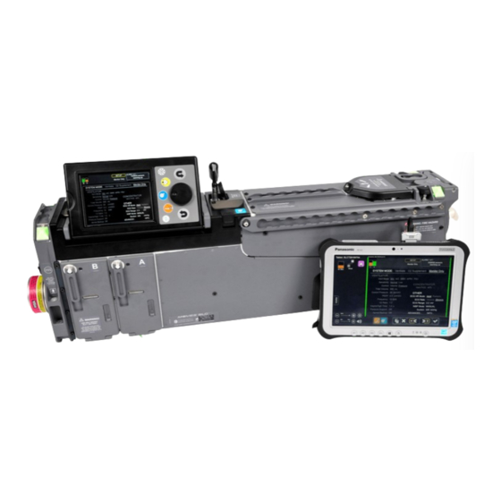
SLC™ Operator’s Manual ® Thornhill Research Inc. MOVES 12.0 Using the Remote Screen ® SLC™ can also be used with the remote screen (P/N 126817) shown below. The remote screen is an optional MOVES accessory. ® Figure 12-1: MOVES SLC™ Remote Screen 12.1 OVERVIEW The remote screen interface displays the same program screens (except for the System Test screen) as the local user... -
Page 208: Replacing / Installing The Remote Screen Battery
SLC™ Operator’s Manual ® MOVES Thornhill Research Inc. 12.2 REPLACING / INSTALLING THE REMOTE SCREEN BATTERY ® SLC™ remote screen can be run on battery or AC power. The remote screen features a 10-hour battery life The MOVES as well as a bridge battery configuration which makes batteries hot swappable. The second battery allows the user to change batteries without having to power off the device. - Page 209 SLC™ Operator’s Manual ® Thornhill Research Inc. MOVES Undo the two hooks attaching the straps. Then shunt the X-strap to the left. 4. An inserted battery is shown in the photo at right. Battery...
- Page 210 SLC™ Operator’s Manual ® MOVES Thornhill Research Inc. 5. To release and remove the battery, push the Lock button (#1) up to unlock the battery. Then push the Release button (#2) to the right to release the battery. 6. Lift out the battery by the handle indicated in the photo at the right.
- Page 211 SLC™ Operator’s Manual ® Thornhill Research Inc. MOVES 8. Do not touch the terminals of the battery pack or the computer. Doing so can make the terminals dirty or damage them which may cause the battery pack or the remote screen to malfunction. 9.
- Page 212 SLC™ Operator’s Manual ® MOVES Thornhill Research Inc. 10. Then press it down until it snaps into place. 11. Lastly, push the Lock button in the direction of the arrow to lock the battery in place. 12. Reinstall the X-strap (See Steps 3 – 1).
-
Page 213: Connecting The Remote Screen To Wall Power
SLC™ Operator’s Manual ® Thornhill Research Inc. MOVES 12.3 CONNECTING THE REMOTE SCREEN TO WALL POWER 1. The cord shown at right, which includes an AC to DC adaptor, is used to connect wall power to the remote screen. 2. The DC connection for the remote screen is located under a plastic cap in the bottom left corner . - Page 214 SLC™ Operator’s Manual ® MOVES Thornhill Research Inc. 3. The plastic cap covering the DC connection is shown in the photo at right. To access the connection, lift the cap from the bottom. Lift Here 4. The DC connection is shown in the photo at the right.
-
Page 215: Remote Screen Indicators
SLC™ Operator’s Manual ® Thornhill Research Inc. MOVES 5. Power cord connected. NOTE: The Installed battery is automatically recharged if it is below a full charge when wall power is connected to the remote screen. 12.4 REMOTE SCREEN INDICATORS Figure 12-2: Remote Screen Indicators... -
Page 216: Remote Screen Battery Status
SLC™ Operator’s Manual ® MOVES Thornhill Research Inc. Table 31: Remote Screen Indicators Indicator Function / Properties Power Switch To start, press and hold the power switch until the power indicator lights. To turn off the remote screen, press and hold the power switch for four (4) seconds. -
Page 217: Slc
SLC™ Operator’s Manual ® Thornhill Research Inc. MOVES Battery Indicator Battery Status Blinking Orange The battery cannot be charged temporarily due to the following reasons: • Its internal temperature is out of the acceptable range. • The power supply is not enough because software applications or peripheral devices are consuming a large amount of power. - Page 218 SLC™ Operator’s Manual ® MOVES Thornhill Research Inc. 1. Locate the serial port connection on the top side of the remote screen. The door indicated in the photo at the right is covering the serial port connection Push forward, then lift door up.
- Page 219 SLC™ Operator’s Manual ® Thornhill Research Inc. MOVES 3. Attach the small end of the short black cable to the remote screen by pushing it in and tightening the screw-in fasteners on either side. Make sure the cable is properly aligned. Do not force it. If the remote screen is lying face down, as in the photo, the wider side of the black cable connector should be facing up.
- Page 220 SLC™ Operator’s Manual ® MOVES Thornhill Research Inc. ® 5. Now connect the circular end of the MOVES SLC™ cable shown at the right to the auxiliary ® communication port on MOVES SLC™. ® 6. The auxiliary communication port on MOVES SLC™...
-
Page 221: Activating The Wired Connection
SLC™ Operator’s Manual ® Thornhill Research Inc. MOVES 8. Align the two slot keys on the remote screen cable connector with the two receiving channels in the auxiliary communication port connection and insert. 9. The remote screen cable connector is shown connected to the auxiliary communication port on ®... -
Page 222: The Remote Screen User Interface (Ui)
SLC™ Operator’s Manual ® MOVES Thornhill Research Inc. 12.7 THE REMOTE SCREEN USER INTERFACE (UI) 12.7.1 First Connecting At first, the user will see the Initial screen. The information on the Initial screen may vary. What the Initial screen displays depends on whether the remote screen is starting from a total disconnect or from the hibernate/sleep state (i.e., whether ®... -
Page 223: The Dashboard
SLC™ Operator’s Manual ® Thornhill Research Inc. MOVES Dashboard Figure 12-4: Main Remote Screen – Connecting and Resources Loaded NOTE: In this second instance, sometimes the connection is so quick that the Initial screen is barely visible. 12.7.2 The Dashboard The Dashboard contains the following: •... -
Page 224: Figure 12-5: The Status Bar
SLC™ Operator’s Manual ® MOVES Thornhill Research Inc. Wall Power Indicator & Battery Level Alarm Audio Pause/Disable Connection State Icon Tab to Access Admin Options Screen Brightness Alarm Volume Figure 12-5: The Status Bar BATTERY CHARGE LEVEL & WALL POWER CONNECTION INDICATOR A wall plug icon is shown if the tablet is connected to wall power. -
Page 225: No System Test Screen
SLC™ Operator’s Manual ® Thornhill Research Inc. MOVES Figure 12-6: Remote Screen Alarm Audio Options NOTE: Disabling the alarm audio must be allowed by the Administrator. If it is not allowed, it will not appear as an option. ADMIN (ADMINISTRATOR) TAB The Admin tab is not to be used by the operator. -
Page 226: Figure 12-8: Setup Screen - Initializing
SLC™ Operator’s Manual ® MOVES Thornhill Research Inc. Mode cannot be modified on the Setup screen; however, the settings on the Setup screen can be preconfigured in preparation for use after the System Tests are complete. NOTE: The following screens are shown without the Dashboard for the sake of clarity. Figure 12-8: Setup Screen –... -
Page 227: Figure 12-9: Setup Screen - Monitor Only Mode
SLC™ Operator’s Manual ® Thornhill Research Inc. MOVES Figure 12-9: Setup Screen – Monitor Only Mode ® SLC™, the Setup screen on the remote screen “times out” or Just as on the display that is physically apart of MOVES defaults to the Main screen after one minute of inactivity so that patient monitoring can be maintained. The only exception to this is the ECG screen. -
Page 228: Remote Screen Panel Buttons
SLC™ Operator’s Manual ® MOVES Thornhill Research Inc. Figure 12-10: Main Screen – On Remote Screen 12.7.4 Remote Screen Panel Buttons NAVIGATING AND SELECTING VIA PANEL BUTTONS Because the remote screen does not use a jog wheel, navigation is controlled by the use of buttons, shown below at the ®... -
Page 229: Graphs Independently Configurable
SLC™ Operator’s Manual ® Thornhill Research Inc. MOVES Table 32: Buttons on the Remote Screen Buttons on the Remote Screen Screen Button Press the Screen button to move to the next screen in sequence. If there are outstanding queries or parameters that need to be satisfied, the functionality of the Screen button will be inhibited until these queries or parameters are satisfied. -
Page 230: Table 33: Alarm Side Bar States And Explanations
SLC™ Operator’s Manual ® MOVES Thornhill Research Inc. The severity of the highest priority active alarm is shown. If the highest priority active alarm is turned off, the bars display the severity of the next highest priority active alarm which is turned on. The color-coding indicates the same alarm states. Table 33: Alarm Side Bar States and Explanations Status Activity... -
Page 231: Figure 12-13: Red Bars Indicating High-Priority Alarm Active
SLC™ Operator’s Manual ® Thornhill Research Inc. MOVES Figure 12-13: Red Bars Indicating High-Priority Alarm Active Figure 12-14: Yellow Bars Indicating Low or Medium Priority Alarm Active... -
Page 232: Remote Screen Software Version
SLC™ Operator’s Manual ® MOVES Thornhill Research Inc. 12.7.7 Remote Screen Software Version The remote screen version can be determined by accessing the Info Screen. For information on accessing the Info Screen, see Section 11.5.1 Accessing the Info Screen on page 170. Figure 12-15: Info Screen Showing Remote Screen Version... -
Page 233: 13.0 Connecting The Patient
SLC™ Operator’s Manual ® Thornhill Research Inc. MOVES 13.0 Connecting the Patient 13.1 CONNECTION OVERVIEW The patient may be intubated, in which case the patient will be connected to a ventilator breathing circuit. The patient may also be breathing spontaneously but be receiving supplemental oxygen via a nasal cannula (nasal prongs) or oxygen mask. -
Page 234: Attaching The Ear Or Finger Clip Pulse Co-Oximeter Sensor
SLC™ Operator’s Manual ® MOVES Thornhill Research Inc. 13.4 ATTACHING THE EAR OR FINGER CLIP PULSE CO-OXIMETER SENSOR NOTE: It is recommended that a pulse oximeter is always used to ensure adequate patient oxygenation. ® SLC™ system comes with some or all of the pulse CO-oximeter sensors listed in the following table. The MOVES Sensor position and whether the sensor is reusable or disposable is also indicated. - Page 235 SLC™ Operator’s Manual ® Thornhill Research Inc. MOVES Sensor Position Reusable / Disposable Any of the five (5) fingers on either Disposable (i.e., single use) 14. Adult SpO , SpCO and SpMet hand (but not the toes) Adhesive Sensor ® (Rainbow R25) Any of the five (5) fingers on either...
-
Page 236: Figure 13-1: 1 Of 5 Possible Sensor Finger Placements
SLC™ Operator’s Manual ® MOVES Thornhill Research Inc. The following photographs show correct placement of the finger clip and ear clip sensors. Figure 13-1: 1 of 5 Possible Sensor Finger Placements Figure 13-2: Correct Ear Lobe Sensor Placement AVOIDING INACCURATE READINGS Pulse oximetry sensors work by transmitting red and infrared light through body tissue. -
Page 237: Placement Of The Heart Rate Electrodes
SLC™ Operator’s Manual ® Thornhill Research Inc. MOVES WARNING! CIRCULATION DISTAL TO THE SENSOR SITE SHOULD BE CHECKED ROUTINELY. WARNING! A FUNCTIONAL TESTER CANNOT BE USED TO ASSESS THE ACCURACY OF A PULSE OXIMETER MONITOR OR SENSOR. WARNING! DO NOT USE DAMAGED SENSORS OR PATIENT CABLES. DO NOT USE A SENSOR OR PATIENT CABLE WITH EXPOSED OPTICAL OR ELECTRICAL COMPONENTS. -
Page 238: Correct Electrode Placement
SLC™ Operator’s Manual ® MOVES Thornhill Research Inc. Table 35: ECG Cable Color Coding and Naming Electrode IEC Abbreviation IEC Color AHA Abbreviation AHA Color Right Arm White Left Arm Yellow Black Right Leg Black Green Left Leg Green Chest 1 White-Red Brown-Red Chest 2... -
Page 239: Reducing Artifacts
SLC™ Operator’s Manual ® Thornhill Research Inc. MOVES Figure 13-4: Proper Limb Lead Electrode Placement Figure 13-5: Precordial Leads: V1–V6 Table 36: Proper Placement of Precordial Leads Electrode Identifier Electrode Position on Body Surface V1 / C1 Fourth intercostal space at right border of sternum V2 / C2 Fourth intercostal space at left border of sternum V3 / C3... -
Page 240: Zeroing The Pressure In The Ip Transducer
SLC™ Operator’s Manual ® MOVES Thornhill Research Inc. Figure 13-6: Electrode Package Figure 13-7: Electrode Use By Date 13.6 ZEROING THE PRESSURE IN THE IP TRANSDUCER To zero the pressure in the invasive pressure transducer, turn the stopcock from the horizontal running position to the vertical open-to-ambient-air position. -
Page 241: Transducer Warnings
SLC™ Operator’s Manual ® Thornhill Research Inc. MOVES 13.6.2 Transducer Warnings EXTREME WARNING! WHEN USING FLUID FILLED PRESSURE TRANSDUCERS TO MONITOR INTRACRANIAL PRESSURE (ICP), MAKE SURE THAT THE TRANSDUCER AND THE LINE CONNECTING TO THE PATIENT’S DRAIN ARE FREE OF ANY AIR BUBBLES! EXTREME WARNING! AFTER COMPLETING FILLING THE TRANSDUCER AND THE LINE, DISCONNECT THE FLUID BAG FROM THE TRANSDUCER, AND CAP THE END WITH THE STERILE... -
Page 242: Shutdown Procedures
SLC™ Operator’s Manual ® MOVES Thornhill Research Inc. NOTE: You can adjust suction pressure between 100 and 325 mmHg in increments of 25 mmHg. (For details, see the subsection Changing Settings in the section Setup Screen beginning on page 160.) CAUTION! THE OPERATOR SHOULD ALWAYS HAVE AVAILABLE AN ALTERNATE MEANS OF SUCTION IN THE EVENT OF POWER FAILURE, MECHANICAL FAILURE, OR A SERIOUS OCCLUSION IN THE SUCTION SYSTEM. - Page 243 SLC™ Operator’s Manual ® Thornhill Research Inc. MOVES THIS PAGE DELIBERATELY LEFT BLANK.
-
Page 245: 14.0 Using System Graphs / Trends
SLC™ Operator’s Manual ® Thornhill Research Inc. MOVES 14.0 Using System Graphs / Trends 14.1 OVERVIEW Plotting appears on two graphs on the Main Screen. Either graph can be set to real-time waveforms or TRENDS, which plots historical values over a user-designated time frame (30 minutes, 1, 2, 4, 8, and 16 hours). Figure 14-1: Plotting Graphs on Main Screen The graphs have a vertical scale (from a minimum to a maximum value) for data of interest, and a horizontal time scale. -
Page 246: Available System Graphs / Trends
SLC™ Operator’s Manual ® MOVES Thornhill Research Inc. 14.2 AVAILABLE SYSTEM GRAPHS / TRENDS 14.2.1 System Graphs The following table lists all available System Graphs. Table 37: System Graphs and Parameters GRAPH PARAMETERS Minimum value: -1.1 mV Maximum value: 1.1 mV Vertical sensitivity: Display MAIN Screen... - Page 247 SLC™ Operator’s Manual ® Thornhill Research Inc. MOVES GRAPH PARAMETERS Minimum value: -3.0 mV Maximum value: 3.0 mV Vertical sensitivity: Display MAIN Screen ECG Screen ® SLC™ 4 mm/mV 2 mm/mV MOVES ® SLC™ Remote Screen 5 mm/mV 3 mm/mV MOVES 3.
-
Page 248: System Trends
SLC™ Operator’s Manual ® MOVES Thornhill Research Inc. GRAPH PARAMETERS Minimum value: 0 mmHg Maximum value: 27 mmHg 7. IP–ICP Plotting rate: 7.7 mm/sec Sampling rate: 20.8 Hz Reference line: 14 mmHg Plotting rate: 7.7 mm/sec Sampling rate: 20.8 Hz Reference line: None 8. -
Page 249: Table 38: System Trends And Parameters
SLC™ Operator’s Manual ® Thornhill Research Inc. MOVES • • ICP (available under IP1, IP2, or IP3) SpOC • • NIBP Trend plots can be set to display trend data for: • 30 minutes • 1 hour • 2 hours •... - Page 250 SLC™ Operator’s Manual ® MOVES Thornhill Research Inc. TREND PARAMETERS Time: 30 min, 1, 2, 4, 8, 16, 24 hours Range: 0–40 cmH 7. Trend Plot - PIP Reference line: 30 cmH Time: 30 min, 1, 2, 4, 8, 16, 24 hours Range: 89°F–108°F (32°C–42°C) 8.
-
Page 251: 15.0 Alarms
SLC™ Operator’s Manual ® Thornhill Research Inc. MOVES 15.0 Alarms Alarm conditions which require immediate or priority user attention can be distinguished from normal status alarms at a distance via their highlighted screen colors, audible annunciation, and alarm status LEDs. If a user is too far away from ®... -
Page 252: High Priority Communication Failure Alarm
SLC™ Operator’s Manual ® MOVES Thornhill Research Inc. ALARMS TABLE Visible Alarm Audible Alarm Alarm Priority Description / Response Medium Prompt operator response Three notes of equal, medium length Yellow LED required and ascending pitch. The musical 60% duty cycle at 0.8 Hz sequence is a common triad (C-E-G). -
Page 253: Locked Alarms And Messages
SLC™ Operator’s Manual ® Thornhill Research Inc. MOVES 15.4 LOCKED ALARMS AND MESSAGES Some alarms and messages CANNOT be turned off or altered in any way, even by someone with Administrator privileges. These alarms and messages are shown with a padlock beside them in the alarm list on the Alarm ON/OFF screen. -
Page 254: Latching Alarms
SLC™ Operator’s Manual ® MOVES Thornhill Research Inc. To clear the Inhibitable alarm, select it in the Alarm Queue using the Jog Wheel and then press the Wheel. Once an alarm is cleared, it will be removed from the Alarm Queue. NOTE: The alarm will, of course, also be cleared if the condition or event that triggered the alarm is addressed or corrected. -
Page 255: Auto Restoration Of Alarm Settings Upon Power Loss
SLC™ Operator’s Manual ® Thornhill Research Inc. MOVES 15.5.4 Auto Restoration of Alarm Settings Upon Power Loss When power is lost for less than or equal to three (3) minutes, the alarm settings prior to the power loss are restored automatically. - Page 256 SLC™ Operator’s Manual ® MOVES Thornhill Research Inc. Alarm Test Procedure Result / Observation Alarm queue should display “High 3. High Expired CO 1. Ensure the O sensor is ” within 20 seconds. warmed up (values populate expired CO “Monitor” screen). 2.
- Page 257 SLC™ Operator’s Manual ® Thornhill Research Inc. MOVES Alarm Test Procedure Result / Observation Alarm queue should display “IPx- 8. IPx-ABP: High systolic pressure 1. Plug the IP cable into one of the 3 ® SLC™ IP ports and into ABP: High systolic pressure”...
-
Page 258: Testing Non-Adjustable Alarms
SLC™ Operator’s Manual ® MOVES Thornhill Research Inc. Alarm Test Procedure Result / Observation Alarm queue should display “IPx: Low 12. IPx: Low ICP 1. Plug the IP cable into one of the 3 ICP” within 20 seconds. ® SLC™ IP ports and into MOVES (where x is 1, 2 or 3) a clinical blood pressure... - Page 259 SLC™ Operator’s Manual ® Thornhill Research Inc. MOVES Alarm Test Procedure Result / Observation Check alarm queue for “Inspired O2 ® 3. Low Oxygen Concentration SLC™ for 1. Setup MOVES below target” alarm within 30 (FiO oxygen supplementation seconds. 2. Redirect the sample line to ambient air.
-
Page 260: Alarm Conditions And Causes
SLC™ Operator’s Manual ® MOVES Thornhill Research Inc. 15.7 ALARM CONDITIONS AND CAUSES NOTE: If no values are given in the Locked / Latching or Inhibitable columns, these conditions do not apply to the listed alarm. Table 42: Alarm Conditions and Causes Priority Locked / Inhibitable... - Page 261 SLC™ Operator’s Manual ® Thornhill Research Inc. MOVES Priority Locked / Inhibitable Alarm / Message Causes Action(s) Latching 4. System Temperature System temperature is less 1. Proceed to a higher temperature too low than -26°C (-14.8°F). environment. ® 2. If erroneous, return MOVES SLC™...
- Page 262 SLC™ Operator’s Manual ® MOVES Thornhill Research Inc. Priority Locked / Inhibitable Alarm / Message Causes Action(s) Latching 8. TEMP2: High patient Patient temperature is over 1. Check integrity of interface with 38°C (100.4°F) and no more patient. than 42°C (107.6°F). 2.
- Page 263 SLC™ Operator’s Manual ® Thornhill Research Inc. MOVES Priority Locked / Inhibitable Alarm / Message Causes Action(s) Latching 13. Concentrator in Medium Concentrator reports partial 1. Monitor inspired O to ensure degraded mode failure due to unexpected adequate oxygenation is being data, including: product tank maintained in the ventilation circuit flow, product tank pressure...
- Page 264 SLC™ Operator’s Manual ® MOVES Thornhill Research Inc. Priority Locked / Inhibitable Alarm / Message Causes Action(s) Latching ® 16. Vent vol-flow fault Medium Ventilator flow sensor SLC™. 1. Power cycle MOVES Try PC-IMV mode if communication failure with 2. Repeat system start-up tests. venting and not ventilator detected during 3.
- Page 265 SLC™ Operator’s Manual ® Thornhill Research Inc. MOVES Priority Locked / Inhibitable Alarm / Message Causes Action(s) Latching 21. Battery A: Unknown Power manager detects 1. Replace affected battery or power level presence of battery but fails to batteries. ® communicate or power SLC™.
- Page 266 SLC™ Operator’s Manual ® MOVES Thornhill Research Inc. Priority Locked / Inhibitable Alarm / Message Causes Action(s) Latching 26. Backup power source High Only one valid power source 1. Connect a second valid power ® required (battery A, battery B or power SLC™.
- Page 267 SLC™ Operator’s Manual ® Thornhill Research Inc. MOVES Priority Locked / Inhibitable Alarm / Message Causes Action(s) Latching ® 29. Patient monitor failure Medium Patient monitor module SLC™. 1. Power cycle MOVES communication failure with ® SLC™ for 2. Return MOVES ®...
- Page 268 SLC™ Operator’s Manual ® MOVES Thornhill Research Inc. Priority Locked / Inhibitable Alarm / Message Causes Action(s) Latching 35. Pulse Ox: Sensor Inhibitable Pulse oximeter patient sensor 1. Fully disconnect then reconnect disconnect cable is disconnected from pulse oximeter patient connection extension cable connected to cable to extension cable, or if system after previously being...
- Page 269 SLC™ Operator’s Manual ® Thornhill Research Inc. MOVES Priority Locked / Inhibitable Alarm / Message Causes Action(s) Latching 39. PulseOx: Check Pulse oximeter sensor at 1. Check integrity of interface with sensor system or patient is patient. compromised. 2. Fully disconnect then reconnect pulse oximeter patient sensor to system.
- Page 270 SLC™ Operator’s Manual ® MOVES Thornhill Research Inc. Priority Locked / Inhibitable Alarm / Message Causes Action(s) Latching 41. PulseOx: Interference High intensity light such as 1. Shield the sensor from excessive detected pulsating strobe lights, or strobing light. Minimize or excessive ambient light eliminate motion at the monitoring sources such as surgical...
- Page 271 SLC™ Operator’s Manual ® Thornhill Research Inc. MOVES Priority Locked / Inhibitable Alarm / Message Causes Action(s) Latching 43. PulseOx: Low SpCO Inhibitable Pulse oximeter detects low 1. Check placement of sensor or if it perfusion perfusion related to SpCO is too tight.
- Page 272 SLC™ Operator’s Manual ® MOVES Thornhill Research Inc. Priority Locked / Inhibitable Alarm / Message Causes Action(s) Latching 45. PulseOx: Low SpHb Inhibitable Pulse oximeter detects low 1. Check placement of sensor or if it perfusion perfusion related to SpHb is too tight.
- Page 273 SLC™ Operator’s Manual ® Thornhill Research Inc. MOVES Priority Locked / Inhibitable Alarm / Message Causes Action(s) Latching 47. PulseOx: SpO2 Pulse oximeter indicating low 1. Check and see if blood flow to the reading confidence monitoring site is restricted. confidence in SpO poor 2.
- Page 274 SLC™ Operator’s Manual ® MOVES Thornhill Research Inc. Priority Locked / Inhibitable Alarm / Message Causes Action(s) Latching 49. PulseOx: PI reading Pulse oximeter indicating low 1. Check and see if blood flow to the confidence poor confidence in perfusion index monitoring site is restricted.
- Page 275 SLC™ Operator’s Manual ® Thornhill Research Inc. MOVES Priority Locked / Inhibitable Alarm / Message Causes Action(s) Latching 51. PulseOx: SpMet Pulse oximeter indicating low 1. Check and see if blood flow to the reading confidence confidence in SpMet monitoring site is restricted. poor measurement value due to 2.
- Page 276 SLC™ Operator’s Manual ® MOVES Thornhill Research Inc. Priority Locked / Inhibitable Alarm / Message Causes Action(s) Latching 53. PulseOx: SpOC Pulse oximeter indicating low 1. Check and see if blood flow to the reading confidence confidence in SpOC monitoring site is restricted. poor measurement value due to 2.
- Page 277 SLC™ Operator’s Manual ® Thornhill Research Inc. MOVES Priority Locked / Inhibitable Alarm / Message Causes Action(s) Latching 55. PulseOx: Only SpO2 Inhibitable SpCO, SpMet, SpHb and 1. Fully disconnect and reconnect available SpOC measurements pulse oximeter patient sensor to unavailable due to failed patient.
- Page 278 SLC™ Operator’s Manual ® MOVES Thornhill Research Inc. Priority Locked / Inhibitable Alarm / Message Causes Action(s) Latching ® 58. Gas sensor pressure Medium SLC™. Mismatch between O 1. Power cycle MOVES fault ® SLC™ for sensor pressures, 2. Return MOVES indicating one of the sensors servicing.
- Page 279 SLC™ Operator’s Manual ® Thornhill Research Inc. MOVES Priority Locked / Inhibitable Alarm / Message Causes Action(s) Latching 62. O2 reading may be High 1. Ensure there are no obstructions O2 reading determined to be biased high to the gas calibration port on the greater than 22.4% when patient monitor panel.
- Page 280 SLC™ Operator’s Manual ® MOVES Thornhill Research Inc. Priority Locked / Inhibitable Alarm / Message Causes Action(s) Latching 66. Inspired O2 low High Ventilate Mode Inspired O is less than 19% (while running in ventilate 1. Ensure sample line with Nafion mode) and filters is connected to system and breathing circuit.
- Page 281 SLC™ Operator’s Manual ® Thornhill Research Inc. MOVES Priority Locked / Inhibitable Alarm / Message Causes Action(s) Latching 68. Inspired O2 below 1. Check for related alarms and Inspired O is not within 5% of target follow actions if required. Vent O setting while running 2.
- Page 282 SLC™ Operator’s Manual ® MOVES Thornhill Research Inc. Priority Locked / Inhibitable Alarm / Message Causes Action(s) Latching 72. Low SpO2 Low until 1. Check for related alarms and saturation level is less follow actions if required. than or equal to user-set low 2.
- Page 283 SLC™ Operator’s Manual ® Thornhill Research Inc. MOVES Priority Locked / Inhibitable Alarm / Message Causes Action(s) Latching 76. High SpCO High SpCO greater than or equal to 1. Check for related alarms and the operator set high SpCO follow actions if required. alarm limit.
- Page 284 SLC™ Operator’s Manual ® MOVES Thornhill Research Inc. Priority Locked / Inhibitable Alarm / Message Causes Action(s) Latching 82. Apnea (Ventilator) High 1. Check for related alarms and While running in PSV follow actions if required. ventilator mode with Pressure 2.
- Page 285 SLC™ Operator’s Manual ® Thornhill Research Inc. MOVES Priority Locked / Inhibitable Alarm / Message Causes Action(s) Latching 86. High pulse rate High, if Heart rate is greater than 1. Check for related alarms and heart rate is operator set high HR alarm follow actions if required.
- Page 286 SLC™ Operator’s Manual ® MOVES Thornhill Research Inc. Priority Locked / Inhibitable Alarm / Message Causes Action(s) Latching 91. Above target volume Medium Exhaled tidal volume is at 1. Check for related alarms and least 15% greater than the follow actions if required. current operator set point and 2.
- Page 287 SLC™ Operator’s Manual ® Thornhill Research Inc. MOVES Priority Locked / Inhibitable Alarm / Message Causes Action(s) Latching 97. NIBP: High diastolic High, if Inhibitable Diastolic pressure of ABP 1. Check for related alarms and pressure diastolic measurement is greater than follow actions if required.
- Page 288 SLC™ Operator’s Manual ® MOVES Thornhill Research Inc. Priority Locked / Inhibitable Alarm / Message Causes Action(s) Latching 100. NIBP set to: Locked & Inhibitable NIBP measurement was not 1. Attempt another NIBP reading. Manual update Latching obtained three consecutive 2.
- Page 289 SLC™ Operator’s Manual ® Thornhill Research Inc. MOVES Priority Locked / Inhibitable Alarm / Message Causes Action(s) Latching 104. IP1: Measurement IP measurement contains 1. Fully disconnect then reconnect IP error values that are outside of the patient connection and zero IP measurement range of the transducer as prompted.
- Page 290 SLC™ Operator’s Manual ® MOVES Thornhill Research Inc. Priority Locked / Inhibitable Alarm / Message Causes Action(s) Latching 108. IP1-ABP: High High, if Systolic pressure of ABP 1. Check for related alarms and systolic pressure systolic measurement is greater than follow actions if required.
- Page 291 SLC™ Operator’s Manual ® Thornhill Research Inc. MOVES Priority Locked / Inhibitable Alarm / Message Causes Action(s) Latching 112. IP1: High CVP Medium CVP measurement is greater 1. Check for related alarms and than or equal to the operator follow actions if required. set high CVP alarm limit.
- Page 292 SLC™ Operator’s Manual ® MOVES Thornhill Research Inc. Priority Locked / Inhibitable Alarm / Message Causes Action(s) Latching 117. IP2: Zero failed Inhibitable IP one-point zero calibration 1. Ensure transducer is ready to zero (Can be set has failed. (i.e., not connected to patient). by System 2.
- Page 293 SLC™ Operator’s Manual ® Thornhill Research Inc. MOVES Priority Locked / Inhibitable Alarm / Message Causes Action(s) Latching 121. IP2-ABP: High High, if Diastolic pressure of ABP 1. Check for related alarms and diastolic pressure diastolic measurement is greater than follow actions if required.
- Page 294 SLC™ Operator’s Manual ® MOVES Thornhill Research Inc. Priority Locked / Inhibitable Alarm / Message Causes Action(s) Latching 126. IP3: Measurement IP measurement contains 1. Fully disconnect then reconnect IP error values that are outside of the patient connection and zero IP measurement range of the transducer as prompted.
- Page 295 SLC™ Operator’s Manual ® Thornhill Research Inc. MOVES Priority Locked / Inhibitable Alarm / Message Causes Action(s) Latching 130. IP3-ABP: High High, if Systolic pressure of ABP 1. Check for related alarms and systolic pressure systolic measurement is greater than follow actions if required.
- Page 296 SLC™ Operator’s Manual ® MOVES Thornhill Research Inc. Priority Locked / Inhibitable Alarm / Message Causes Action(s) Latching 134. IP3: High CVP Medium CVP measurement is greater 1. Check for related alarms and than or equal to the operator follow actions if required. set high CVP alarm limit.
- Page 297 SLC™ Operator’s Manual ® Thornhill Research Inc. MOVES Priority Locked / Inhibitable Alarm / Message Causes Action(s) Latching 141. Target pressure Medium Peak inspiratory pressure 1. Check for related alarms and not reached follow actions if required. (PIP) is ± 5 cmH O or greater 2.
- Page 298 SLC™ Operator’s Manual ® MOVES Thornhill Research Inc. Priority Locked / Inhibitable Alarm / Message Causes Action(s) Latching 146. Patient circuit Medium Inspired tidal volume is at 1. Ensure breathing circuit patient occlusion least 15% less than the tubing is not kinked or obstructed. current operator set point, and 2.
- Page 299 SLC™ Operator’s Manual ® Thornhill Research Inc. MOVES Priority Locked / Inhibitable Alarm / Message Causes Action(s) Latching 147. Patient circuit High While ventilating, any of the 1. Ensure all breathing circuit disconnect following conditions occur: connections (including patient tubing, Y-piece and sample line) a) Expiratory flow never are tight and no leaks are exceeds inspiratory flow...
- Page 300 SLC™ Operator’s Manual ® MOVES Thornhill Research Inc. Priority Locked / Inhibitable Alarm / Message Causes Action(s) Latching 148. Concentrator air High Pressure at concentrator air 1. Check for and remove any intake filter intake filter exceeds expected obstructions from intake filter (i.e., blocked value (above normal hydrocarbon filter).
- Page 301 SLC™ Operator’s Manual ® Thornhill Research Inc. MOVES Priority Locked / Inhibitable Alarm / Message Causes Action(s) Latching ® 153. Alarm indication Medium Locked SLC™. Communication failure with 1. Power cycle MOVES failure Alarm board, which controls ® SLC™ for 2.
- Page 302 SLC™ Operator’s Manual ® MOVES Thornhill Research Inc. Priority Locked / Inhibitable Alarm / Message Causes Action(s) Latching 156. Remote Screen Medium Locked Inhibitable Remote Screen was 1. Check cable connection disconnect connected and became 2. Confirm that both devices are still disconnected.
-
Page 303: System Test Failure Messages And Causes
SLC™ Operator’s Manual ® Thornhill Research Inc. MOVES 15.8 SYSTEM TEST FAILURE MESSAGES AND CAUSES Table 43: System Test Failure Messages and Causes System Prompt Causes/Actions 1. The ventilator is not responding correctly. Displayed if ventilator fails to respond appropriately during initialization for testing. - Page 304 SLC™ Operator’s Manual ® MOVES Thornhill Research Inc. System Prompt Causes/Actions 6. Ensure that Y-Piece is disconnected from the Failure of open Y-piece ventilator test, specifically the flow patient accuracy of the air pump. and kept stationary during test. 1. Confirm that the breathing circuit is connected to the system correctly.
- Page 305 SLC™ Operator’s Manual ® Thornhill Research Inc. MOVES System Prompt Causes/Actions 10. Unable to verify clear sample line. Ensure sample Displayed if unable to establish a stable clear-line line is not kinked or blocked, and occluding cap is condition during Sample Line testing. removed.
-
Page 306: Safe Gas Mode
SLC™ Operator’s Manual ® MOVES Thornhill Research Inc. System Prompt Causes/Actions 15. The system requires a backup source of power. Displayed if the backup power source verification test fails Ensure that either wall power is present and a to detect the presence of redundant power. charged backup battery is installed or that two 1. -
Page 307: Figure 15-8: Status Bar Showing System In Safe Gas Mode
SLC™ Operator’s Manual ® Thornhill Research Inc. MOVES The system automatically enters SGM whenever the system cannot rely on the oxygen (O and/or carbon dioxide (CO value that it is sensing. It is also used (when ventilating) if inspired CO becomes too high due to an exhausted ventilator cartridge. -
Page 309: System Default Settings
SLC™ Operator’s Manual ® Thornhill Research Inc. MOVES 16.0 Appendix A 16.1 SYSTEM DEFAULT SETTINGS Table 44: System Default Settings Setting Default Alarms All alarms and audio enabled System Mode Monitor Only Vent Mode Vent Control Pressure 500 ml (not used by default vent mode PC-IMV) Frequency 10 B/M PEEP... - Page 310 SLC™ Operator’s Manual ® MOVES Thornhill Research Inc. Setting Default ECG EMG Filter High airway pressure warning alarm limit Dependent on System Administration Airway/ICP units, either: • 32 cmH • 32 hPa High airway pressure release alarm limit Dependent on System Administration Airway/ICP units, either: •...
-
Page 311: System Cleaning
SLC™ Operator’s Manual ® Thornhill Research Inc. MOVES Setting Default • 170 g Hb / L blood Low SpOC alarm limit 10 mL O / dL blood High SpOC alarm limit 25 mL O / dL blood 16.2 SYSTEM CLEANING The external body of the system can be cleaned using standard cleaning agents, excluding oxidizing agents. -
Page 312: System Maintenance
SLC™ Operator’s Manual ® MOVES Thornhill Research Inc. 16.3 SYSTEM MAINTENANCE CAUTION! NO LUBRICANTS OTHER THAN THOSE RECOMMENDED BY THE MANUFACTURER ® SHALL BE USED ON THE MOVES SLC™. ® Regular maintenance and calibration should be carried out on the MOVES SLC™... -
Page 313: User Serviceable Components
SLC™ Operator’s Manual ® Thornhill Research Inc. MOVES MAINTENANCE FREQUENCY MAINTENANCE PROCEDURE # MAINTENANCE MAINTENANCE PROCEDURE ITEM KIT PART DESCRIPTION NUMBER PROCEDURES ARE COMPLETED • REPLACE VENTILATOR ® Removal/Replacement Refer to Service 125943 Kit, MOVES of the Ventilator Bag Manual BAG AFTER EACH VENT SLC™, Ventilator RUNTIME OF 2000 hours... - Page 314 SLC™ Operator’s Manual ® MOVES Thornhill Research Inc. 3. Lift the Ventilator Filter Cover and locate the filter 4. Press the filter frame down while turning counterclockwise. 5. Remove the filter 6. Once the old Ventilator Filter has been removed, it should be discarded in accordance with local regulations.
-
Page 315: Replacing The Hydrocarbon Filter
SLC™ Operator’s Manual ® Thornhill Research Inc. MOVES 16.3.3 Replacing the Hydrocarbon Filter ® Purchase Kit Part # 124354 – Kit, MOVES SLC™, Hydrocarbon Filter, 6pk and read the entire procedure before starting. 1. Locate the Hydrocarbon Filter (P/N 100915) at ®... - Page 316 SLC™ Operator’s Manual ® MOVES Thornhill Research Inc. 3. In the photo on the right, the old Hydrocarbon Filter (P/N 100915) has been removed. Once it is removed, it should be disposed of in accordance with local regulations. 4. Before installing the new Hydrocarbon Filter (P/N 100915), check the four-digit date code printed on the cartridge.
-
Page 317: Replacing The Ventilator Liner
SLC™ Operator’s Manual ® Thornhill Research Inc. MOVES 16.3.4 Replacing the Ventilator Liner ® Purchase Kit Part # 127407 – Kit, MOVES SLC™, Ventilator Liner, 10pk and read the entire procedure before starting. 1. Open the ventilator door and locate the liner. NOTE: The ventilator cartridge should never be left inside after the unit is used. - Page 318 SLC™ Operator’s Manual ® MOVES Thornhill Research Inc. 3. Pull the liner forward until it is fully removed from the cavity 4. Discard the old Liner 5. Clean the Ventilator Chamber and door with a wet cloth and mild detergent if needed. Do not allow any cleaning product to reach any chamber opening...
- Page 319 SLC™ Operator’s Manual ® Thornhill Research Inc. MOVES 6. Place the new Liner on the middle tube. Pay attention to the orientation of the Liner. The Liner’s water collecting cavity should be at the bottom. 7. Slowly push the liner forward until its bottom reaches the back wall of the chamber.
-
Page 320: Exercising The Oxygen Concentrator
SLC™ Operator’s Manual ® MOVES Thornhill Research Inc. 10. Rotate the liner about the middle tube until the inspiratory hole matches the corresponding liner hole. 16.3.5 Exercising the Oxygen Concentrator If the system is not in use, it should be removed from storage every 3 months and run in O2 supplement mode for at least 2 hours. -
Page 321: Accessories Maintenance
SLC™ Operator’s Manual ® Thornhill Research Inc. MOVES 16.4 ACCESSORIES MAINTENANCE Reusable accessories should be regularly inspected for wear or damage. Inspect all cables and connections (especially the power cord) for signs of fraying or other damage. Keep accessories clean. Refer to original manufacturer’s instructions for cleaning agents and procedures. - Page 322 SLC™ Operator’s Manual ® MOVES Thornhill Research Inc. Property Specification Notes Standards Compliance IEC/EN 60601-1 IEC 60601-1-2 IEC 60601-1-8 ISO 80601-2-12 IEC 60601-2-27 IEC 80601-2-30 IEC 60601-2-34 IEC 60601-2-49 ISO 80601-2-55 ISO 80601-2-61 ISO 8359 ASTM E1112-00 BS EN 794-3 (2009) MIL-STD-810G JECETS Device Classification...
-
Page 323: Oxygen Concentrator Specifications
SLC™ Operator’s Manual ® Thornhill Research Inc. MOVES 16.6.3 Oxygen Concentrator Specifications ® Table 46: Oxygen Concentrator Specifications of MOVES SLC™ in a Circle Circuit Property Specification Notes Temp (°C) Time (min.) All figures measured with a 1 L test lung Time to FiO from cold start. -
Page 324: Ventilator Specifications And Vent Mode Definitions
SLC™ Operator’s Manual ® MOVES Thornhill Research Inc. Property Specification Notes Flow None @ 1 PSI (7 kPa) backpressure, O flow is measured as 2.4 LPM @ 0 PSI (0 kPa) backpressure, O flow is measured as 2.5 LPM Low O2 Alarm <... - Page 325 SLC™ Operator’s Manual ® Thornhill Research Inc. MOVES Triggers: Time or pressure/flow Description: Produces a mandatory breath at the specified frequency, or faster if triggered by patient pressure/flow. The breath is divided into an inspire and expire period as specified by the set I:E ratio. Inspiration starts at the specified PEEP pressure and linearly increases the delivered volume to the specified tidal volume over the inspire time.
-
Page 326: Table 48: Ventilator Specifications Of Moves ® Slc
SLC™ Operator’s Manual ® MOVES Thornhill Research Inc. Triggering: In normal sensitivity, a patient can trigger the start of inspiration with an inspiratory flow of at least 10 L/min or by causing a pressure drop of 3.0 cmH 0 from PEEP. In low sensitivity, the flow must exceed 15 L/min or the pressure drops 6 cmH 0 from PEEP. - Page 327 SLC™ Operator’s Manual ® Thornhill Research Inc. MOVES Property Specification Inspiratory Time 0.3–5.0 seconds Peak Flow 60 LPM Positive End Expiratory Pressure (PEEP) 0–20 cmH Positive Pressure Relief Valve (Mechanical) 70 cmH Control Pressure 10–55 cmH O (over PEEP). Control Pressure = PIP (Peak Inspiratory Pressure) –...
-
Page 328: Suction Specifications
SLC™ Operator’s Manual ® MOVES Thornhill Research Inc. Property Specification Tidal volume of 150 mL at 20 breaths/minute into a test lung with 20 cmH2O/L/s resistance and 20 mL/cmH2O compliance At oxygen flow of 5 LPM = 2:28 minutes At oxygen flow of 15 LPM = 2:00 minutes Ventilator Breathing System Filter characteristics Internal Volume of 85 mL (standard circuit with PALL Medical BB100E) -
Page 329: Environmental Specifications
SLC™ Operator’s Manual ® Thornhill Research Inc. MOVES 16.6.7 Environmental Specifications ® MOVES SLC ™ ® SLC™ has been tested to function under the environmental conditions present during transport and battlefield MOVES use. These included mechanical testing for vibration, bump and shock as well as EMC and extreme temperature humidity and weather conditions. - Page 330 SLC™ Operator’s Manual ® MOVES Thornhill Research Inc. Variable Storage Condition Operating Condition • Mechanical Strength Composite Wheeled Transport Vibration (sinusoidal) according to Vibration (JECETS) IEC 60068-2-6 • Random vibration wide band – Reproducibility Medium according to IEC 60068-2-36 • Bump according to IEC 60068-2-29 •...
-
Page 331: Patient Monitoring Specifications
SLC™ Operator’s Manual ® Thornhill Research Inc. MOVES REMOTE SCREEN Table 52: Environmental Specifications of the Remote Screen Variable Storage Condition Operating Condition Temperature 14°F to 122°F (–10°C to 50°C). –4ºF to 140ºF (–20ºC to 60ºC) Relative Humidity 30% to 90% non-condensing 30% to 80% non-condensing NOTE: Even within the above temperature/humidity ranges, operation for a long time in extreme environments, smoking nearby, or operation in places where oil is used or where there is a lot of dust will... -
Page 332: Temperature Monitoring Specifications
SLC™ Operator’s Manual ® MOVES Thornhill Research Inc. Item Specification Alarm Condition Delay (onset of condition to internal ABP: 6 beats + 100 ms realization) SpO2: SpO average time + 100 ms NOTE: "Alarm Condition Delay" derives its value from ECG: 8 beats + 100 ms "Fixed Delays Due To Signal Processing"... -
Page 333: Co 2 Monitoring Specifications
SLC™ Operator’s Manual ® Thornhill Research Inc. MOVES Item Specification – 60 to 60 LPM Inspiratory/Expiratory Flow Range 0.5% (% of reading) Repeatability of Inspiratory/Expiratory Flow Measure Airway Pressure (Paw) Range – 5 to 70 cmH 2 cmH Accuracy of Airway Pressure Measure O + 4% of reading ... -
Page 334: O 2 Monitoring Specifications
SLC™ Operator’s Manual ® MOVES Thornhill Research Inc. 16.7.6 Monitoring Specifications ® Table 58: O 2 Monitoring Specifications of MOVES SLC™ Item Specification Range 5 to 100% by Volume Resolution 0.02% 4% Absolute Accuracy Rise Time 150 ms (10-90%) at 150 ml/min Response time of gas sample readings <... -
Page 335: Table 60: 3-Lead Ecg Specifications Of Moves ® Slc
SLC™ Operator’s Manual ® Thornhill Research Inc. MOVES Item Specification Defibrillator Protection ST Analysis None Pacer Detection None Standard Complied to IEC 60601–2–27 Maximum T-Wave Amplitude 0.6 mV T-Wave Rejection The tall T-wave rejection is always on. The max T-wave rejection is 0.6 mV when R-wave is 1 mV. - Page 336 SLC™ Operator’s Manual ® MOVES Thornhill Research Inc. Item Specification Input Impedance > 10 MOhm Input Range > 10 mVpp Input Range (DC) > 300 mV Sensitivity See ECG graphs of Section 14.2.1 System Graphs Filtering 50 Hz, 60 Hz; optional 15–30 Hz EMG filter Frequency Response 0.3–70 Hz Pulse Detection...
-
Page 337: Nibp Specifications
SLC™ Operator’s Manual ® Thornhill Research Inc. MOVES Item Specification B1 – Half Amplitude 6.2 seconds B1 – Double Amplitude ± 6 seconds B2 – Regular Amplitude (max) 5 seconds B2 – Half Amplitude (max) 4 seconds B2 – Double Amplitude (max) 4.2 seconds ®... -
Page 338: Pulse Oximetry Specifications
SLC™ Operator’s Manual ® MOVES Thornhill Research Inc. Item Specification Temperature: Operating 15° to 40°C (57°F to 104°F) Storage -25° to 70°C (13°F to 158°F) 4 mmHg or 4% of reading whichever is greater Accuracy Units of measure (pressure) ABP / CVP is mmHg ICP cmH2O or hPa 16.7.10... -
Page 339: Equipment Response Time
SLC™ Operator’s Manual ® Thornhill Research Inc. MOVES 16.7.11 Equipment Response Time Table 64: Pulse Oximetry Equipment Response Time Average Latency Values Choice of 2–4, 4–6, 8, 10, 12, Standard/Fast Averaged SpO 14, or 16 seconds. 2 beats Default: 8 seconds Pulse Rate Values Average Latency... - Page 340 SLC™ Operator’s Manual ® MOVES Thornhill Research Inc. No Motion [2] 70% to 100% Adults/Pediatrics ± 2% Motion [3] 70% to 100% Adults/Pediatrics ± 3% Low Perfusion [4] 70% to 100% Adults/Pediatrics ± 2% Pulse Rate Accuracy [5] Pulse rate range 25 bpm to 239 bpm No Motion Adults/Pediatrics...
- Page 341 SLC™ Operator’s Manual ® Thornhill Research Inc. MOVES 4. The Masimo SET Technology has been validated for low perfusion accuracy in bench top testing against a Biotek Index 2 simulator and Masimo’s simulator with signal strengths of greater than 0.02% and transmission of greater than 5% for saturations ranging from 70 to 100%.
-
Page 342: General Accessories Specifications
SLC™ Operator’s Manual ® MOVES Thornhill Research Inc. 16.8 GENERAL ACCESSORIES SPECIFICATIONS ® Table 65: General Accessories Specifications of MOVES SLC™ Item Category Specification –26ºC to 54ºC (–14°F to 129°F) (cold start Batteries Operating Temperature: above -20ºC) –26ºC to 60ºC (–14°F to 140°F) Storage Temperature: Charging Temperature: 0ºC to 40ºC (32°... - Page 343 SLC™ Operator’s Manual ® Thornhill Research Inc. MOVES Accessory Description ® Rainbow DCI-dc3 Adult Reusable Finger Sensor for SpCO, SpO & SpMet, 3 ft. NOTE: Can be used to measure only SpO if optional SpCO and/or SpMet features have ® SLC™...
-
Page 344: Masimo Pulse Oximeter Accessories Specifications
SLC™ Operator’s Manual ® MOVES Thornhill Research Inc. 16.8.2 Masimo Pulse Oximeter Accessories Specifications Table 67: Masimo Pulse Oximeter Accessories Specifications Sensor Description Preferred Masimo Weight Sp02 SpCO/Hb SpMet Application Range Accuracy Accuracy Perfusion Accuracy Accuracy Site Accuracy Motion Sp02 Motion Motion Motion Motion... - Page 345 SLC™ Operator’s Manual ® Thornhill Research Inc. MOVES Sensor Description Preferred Masimo Weight Sp02 SpCO/Hb SpMet Application Range Accuracy Accuracy Perfusion Accuracy Accuracy Site Accuracy Motion Sp02 Motion Motion Motion Motion Motion M-LNCS Pediatric Finger 2502 10-50 ±2% ±3% ±3 bpm ±5 ±2% ±3...
- Page 346 SLC™ Operator’s Manual ® MOVES Thornhill Research Inc. Sensor Description Preferred Masimo Weight Sp02 SpCO/Hb SpMet Application Range Accuracy Accuracy Perfusion Accuracy Accuracy Site Accuracy Motion Sp02 Motion Motion Motion Motion Motion Rainbow Adult Adhesive Finger 2221 >30 kg 60-80% ±3% ±3 bpm ±5...
-
Page 347: Electromagnetic Conformity Information
SLC™ Operator’s Manual ® Thornhill Research Inc. MOVES 16.9 ELECTROMAGNETIC CONFORMITY INFORMATION 16.9.1 IEC 60601-1-2:2014 (Ed 4.0) Table 1 Requirements ® SLC™ is intended for use in the electromagnetic environment specified below. The customer or the user of MOVES ® SLC™... -
Page 348: Iec 60601-1-2:2014 (Ed 4.0) Table 2 Requirements
SLC™ Operator’s Manual ® MOVES Thornhill Research Inc. 16.9.2 IEC 60601-1-2:2014 (Ed 4.0) Table 2 Requirements ® SLC™ is intended for use in the electromagnetic environment specified below. The customer or the user of MOVES ® SLC™ should assure that it is used in such an environment. MOVES Table 69: 5.2.2.1f IEC 60601-1-2:2014 (Ed 4.0) Table 2 Requirements SLC™... -
Page 349: Iec 60601-1-2:2014 (Ed 4.0) Table 3 Requirements
SLC™ Operator’s Manual ® Thornhill Research Inc. MOVES 16.9.3 IEC 60601-1-2:2014 (Ed 4.0) Table 3 Requirements ® SLC™ is intended for use in the electromagnetic environment specified below. The customer or the user of MOVES ® SLC™ should assure that it is used in such an environment. MOVES Table 70: 5.2.2.2 IEC 60601-1-2:2014 (Ed 4.0) Table 3 Requirements ®... - Page 350 SLC™ Operator’s Manual ® MOVES Thornhill Research Inc. ® MOVES SLC™ IEC 60601 Required Electromagnetic Environment – Guidance Immunity Test Level Compliance Level Radiated RF 30 V/m 80 MHz to 30 V/m IEC 61000-4-3 2.5 GHz Where P is the maximum output power rating of the transmitter in watts (W) according to the transmitter manufacturer and d is the recommended separation distance in meters (m).
-
Page 351: Iec 60601-1-2:2014 (Ed 4.0) Table 5 Requirements
SLC™ Operator’s Manual ® Thornhill Research Inc. MOVES ® MOVES SLC™ IEC 60601 Required Electromagnetic Environment – Guidance Immunity Test Level Compliance Level a) Field strengths from fixed transmitters, such as base stations for radio (cellular/cordless) telephones and land mobile radios, amateur radio, AM and FM radio broadcast and TV broadcast cannot be predicted theoretically with accuracy. -
Page 353: 17.0 Appendix B - Pneumatic Diagram
SLC™ Operator’s Manual ® Thornhill Research Inc. MOVES 17.0 Appendix B – Pneumatic Diagram SLC™ PNEUMATIC DIAGRAM 17.1 ® MOVES External air sample Carbon filter Pressure Transducer Sample Filter Pump Naphion Sample Line Sampling Filter Sampling Filter Sampling Activated One-Way Filter Product Tank Positional Expiratory Relief Valve... - Page 354 SLC™ Operator’s Manual ® MOVES Thornhill Research Inc. THIS PAGE DELIBERATELY LEFT BLANK...
-
Page 355: 18.0 Appendix C - End-User License Agreement
SLC™ Operator’s Manual ® Thornhill Research Inc. MOVES 18.0 Appendix C – End-User License Agreement THIS DOCUMENT IS A LEGAL AGREEMENT BETWEEN YOU (“PURCHASER”) AND Thornhill Research Inc. (“Thornhill”). IF YOU DO NOT AGREE TO THE TERMS OF THIS AGREEMENT, PROMPTLY RETURN THE ENTIRE PACKAGE, INCLUDING ALL ACCESSORIES, IN THEIR ORIGINAL PACKAGE, WITH YOUR SALES RECEIPT TO Thornhill FOR A FULL REFUND. - Page 356 SLC™ Operator’s Manual ® MOVES Thornhill Research Inc. THIS PAGE DELIBERATELY LEFT BLANK...
-
Page 357: 19.0 Index
SLC™ Operator’s Manual ® Thornhill Research Inc. MOVES 19.0 Index visual indicators, 146 A/C - Assist/Control Ventilation about, 310 Alarms, Inhibitable about, 239 AC Power SLC™ to, 139 ® connecting MOVES Alarms, Latching about, 240 Accessories, General specifications, 328 Alarms, Standard types &... - Page 358 SLC™ Operator’s Manual ® MOVES Thornhill Research Inc. overview, 28 Electrodes, Heart Rate Clamps placement of, 223 ® SLC™, 94 attaching to MOVES Electromagnetic Conformity ® SLC™, 98 attaching to side mount MOVES info about, 333 ® SLC™, 95 attaching to top mount MOVES Classification notice about, 2 of equipment, 2...
- Page 359 SLC™ Operator’s Manual ® Thornhill Research Inc. MOVES accessing, 170 attaching clamps to, 94 image of, 172 attaching shoulder strap to, 91 info on, 172 connecting patient monitoring accessories, 107 connecting to power supply / battery charger, 138 Information, Contact consumables, 84 manufacturer, notified body, authorized reps, 1 end of life, 306...
- Page 360 SLC™ Operator’s Manual ® MOVES Thornhill Research Inc. unexpected readings, 66 Panel Buttons unexpectedly high SpCo, 66 on remote screen, 214 Pulse Oximeter Accessories Patent specifications, 330 notice of, 1 Pulse Oximeter Sensor Patient avoiding inaccurate readings, 222 connecting, 219 warnings, 222 Patient Connection Panel Pulse Oximetry...
- Page 361 SLC™ Operator’s Manual ® Thornhill Research Inc. MOVES about, 144 SpO2 Average Time Screen Select Button selecting & description, 169 about, 156 SpO2 Sensitivity Modes Screen, Display Orientation selecting & description, 169 adjusting, 141 SpOC general description for, 63 Sensing Accuracy drift in, 325 Standards, Regulatory Sensors...
- Page 362 SLC™ Operator’s Manual ® MOVES Thornhill Research Inc. overview, 29 Transducer Channel specifications, 310 zeroing, 226 specifications of, 312 Transducer, IP Ventilator Breathing Circuit zeroing pressure in, 226 installing, 114 Trends, System Ventilator Cartridge list of & parameters, 234 installing, 110 overview, 231 using, 108 Troubleshooting...
Need help?
Do you have a question about the MOVES SLC and is the answer not in the manual?
Questions and answers