
Related Manuals for Yamaha YDX-MORO Pro


Summary of Contents for Yamaha YDX-MORO Pro
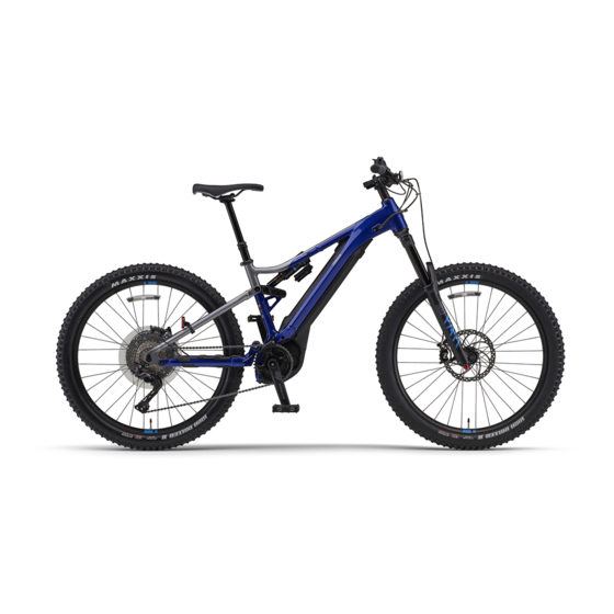
- Page 1 2020 ASSEMBLY MANUAL YDX-MORO Pro YDX-MORO PB65MPL PB65MPM PB65MPS PB65ML PB65MM PB65MS LIT-15666-00-11 X1V-28107-10...
- Page 2 This Assembly Manual contains the information required for the correct assembly of this Yamaha bicycle prior to delivery to the customer. Since some external parts of the bicycle have been removed at the Yamaha fac- tory for the convenience of packing, assembly by the Yamaha dealer is required. No adjustment of the power unit mechanism, which plays the most important part in riding, is necessary because it has been adjusted at the factory before shipping.
-
Page 3: Parts Location
PARTS LOCATION PARTS LOCATION Body assembly NOTICE 8 Do not use a cutter, scissors, or other sharp object to open the part boxes; otherwise, the included parts could be damaged. 8 Wear suitable protective gear such as gloves when handling and opening the part boxes. 1. -
Page 4: Included Parts
Part names Q’ty Remarks Front wheel Part box 1 Part box 2 Part box 3 Part box 1 details Front axle YDX-MORO Pro only Front axle YDX-MORO only Saddle Pedals 1 each for left and right Bell Front reflector Rear reflector Battery end cap r in owner’s manual pouch... - Page 5 INCLUDED PARTS – 3 –...
- Page 6 Give the removed spacers b to the customer, explaining how it is used. (For YDX-MORO Pro) Align the holes in the front wheel 1 with the holes in the fork end and install the front wheel Install it in such a way that the disc rotor c does not touch the disc pad.
- Page 7 INSTALLING THE INCLUDED PARTS Tighten the front axle 2 to the specified torque. Tightening torque 11 N·m (1.1 kgf·m, 8.1 lb·ft) WARNING Tighten the front axle 2 to the specified torque and install it securely. Otherwise, the front wheel could come off. (For YDX-MORO) Align the holes in the front wheel 1 with the holes in the fork end and install the front wheel...
- Page 8 INSTALLING THE INCLUDED PARTS WARNING 8 Position the lever when it cannot touch obstacles while the bicycle is moving. If not, the lever could be unlocked unexpectedly, causing the front wheel to come off, result- ing in an accident with severe injury or death.
- Page 9 INSTALLING THE INCLUDED PARTS 8 Tighten bolts d evenly in stages, in the order shown in the illustration. 8 Tighten in such a way that the gaps e above and below the handlebar holder c are equal. Install the handlebar a so that the brake lever f is at a 30...
- Page 10 INSTALLING THE INCLUDED PARTS NOTICE 8 Install the button cell battery with the plus (+) mark facing upward. 8 Check that the O-ring g is properly installed. After installing the button cell battery, install the display unit onto the bracket following the removal procedure in reverse order.
- Page 11 INSTALLING THE INCLUDED PARTS 8. Routing the wires WARNING Be sure to route the wires as shown in the illus- tration. If not, they could interfere with handle- bar operation which could cause loss of control. Confirm that hoses and wires are routed in order starting from front to back front brake hose 1 rear brake hose 2...
- Page 12 INSTALLING THE INCLUDED PARTS Make sure that the dropper seat wire 3 and compact multifunction meter lead 5 are routed as shown. Make sure that the front brake hose 1, rear brake hose 2, and shift wire 4 are routed as shown.
- Page 13 INSTALLING THE INCLUDED PARTS Check that the rear brake hose 2, shift wire 4, and speed sensor lead e are routed as shown in the illustration. 9. Installing the saddle Pinch the rail of the saddle 1 with the saddle clamps a and b, and then tighten the seat post c, bolts d, and nuts e to the specified torque.
- Page 14 INSTALLING THE INCLUDED PARTS 10. Installing the rear reflector Tightening torque 1.5 N·m (0.15 kgf·m, 1.1 lb·ft) Install the rear reflector 1, band 2, screw 3, and nut 4 as shown, and then tighten them together to the specified torque. Secure them to the frame with the band 2.
- Page 15 INSTALLING THE INCLUDED PARTS 13. Installing the battery pack WARNING Before installing the battery, make sure that there are neither foreign materials nor water at the connection portion between the battery and the bicycle, or charging connector. Otherwise, it could lead to heat generation, smoke and/or a fire.
- Page 16 INSTALLING THE INCLUDED PARTS Hook the claw i of the battery cover to the hook part h of the motor cover, and then install Tightening torque 2.0 N·m (0.20 kgf·m, 1.5 lb·ft) the battery cover c along the frame. Install the collars b (2 pcs), and then tighten the bolts a (2 pcs) to the specified torque.
- Page 17 INSTALLING THE INCLUDED PARTS E. The minutes value increases when the “▲” assist mode switch f is pressed while the “Min- ute” section of the clock e is flashing. The minutes value decreases when the “▼” assist mode switch d is pressed. Press the function select switch b to set the minutes.
- Page 18 INSTALLING THE INCLUDED PARTS NOTICE After adjusting the brake lever opening, check that the rotation of the front and rear wheels is not heavy. Adjust to a position at which it is easy for the cus- tomer to operate the front and rear brake levers and within the range of play of the brake levers.
-
Page 19: Pre-Delivery Inspection
PREDELIVERY INSPECTION PREDELIVERY INSPECTION WARNING After completing the installation, inspect the items as follows and check that there are no problems before delivering the bicycle. Adjust controls and saddle height to the customer’s satisfaction according to this manual. 8 Handlebar orientation, height, angle, and tightening 8 Saddle orientation, height, angle, and tightening * Check that the saddle is firmly fastened.