
Related Manuals for Voxelab Aquila


Summary of Contents for Voxelab Aquila
- Page 1 3D Printer User Manual Aquila Note: Each device must be tested before leaving factory. If there are some residues in extruder or some tiny scratches on the build plate, it is normal and won’t affect the printing quality. V1.3.3-20210302...
- Page 2 Notes For your convenience, please read this manual carefully before use and follow the manual strictly. The Voxelab team is always ready to provide Product Introduction you with the perfect service. Please contact us by email listed, if you have any problems.
- Page 3 Do not directly touch the nozzle and build plate to avoid high-temperature burn. Do not operate the Aquila in flammable liquid, gas or dust environment (The high temperature generated by Aquila operation may react with dust, liquid, and flammable gas in the air to cause a fire.) Do not put the Aquila into the situation in which an unstable environment.
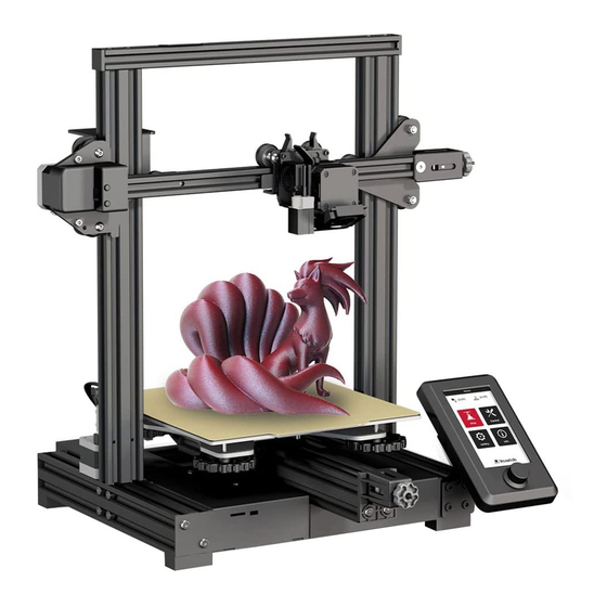
- Page 4 Product Introduction 14 15 XE-axis kit X-axis tensioner Y-axis motor X-axis limit switch Screen E-axis motor Build plate Knob switch X-axis motor Y-axis tensioner Machine base Coupling Extruded kit Power supply Z-axis limit switch Material rack and spool holder Voltage regulator Z-axis motor Z-axis passive block Y-axis limit switch...
- Page 5 Equipment Parameters Model Voxelab Aquila Print size 220*220*250mm Forming technology Number of nozzle Layer thickness 0.1mm - 0.4mm Nozzle diameter Standard 0.4mm XY axis precision ±0.2mm Filament φ1.75mm PLA File format STL / OBJ / AMF Working mode Memory card offline printing or online printing...
- Page 6 Spare Parts Printer base *1 Screen kit *1 Extruder kit *1 Z-axis passive block *1 X-axis tensioner *1 Z-axis motor kit *1 X-axis limit switch kit *1 XE axis kit *1 Z-axis profile(left) *1 Z-axis profile(right) *1 Gantry profile *1 X-axis profile *1 T-shaped screw rod *1...
- Page 7 Spare Parts Synchronous belt *1 Material pipe and Material rack *1 2020 profile cover *2 nut *1 Remove tool *1 Cable tie *1 Storage card and Needle *1 card reader *1 M6 Pneumatic joint *2 Wrenches and Power cable *1 Nozzle *1 screwdrivers *1 Hexagon socket countersunk...
- Page 8 Installation of Z-axis limit switch kit and Z-axis profiles Installation video can be found on Voxelab Youtube channel Printer base *1 Z-axis profile(left) *1 Z-axis profile(right) *1 M5x45 Hexagon socket head spring washer combination screw M5x45 *4 Step: Use the four pieces screws M5x45 to fix Z-axis with the base.
- Page 9 Install Z-axis motor kit and T-shaped screw rod T-shaped screw rod *1 Z-axis motor kit *1 M4x20 Hexagon socket countersunk head screw M4x20 *2 Step: Lock the T-shaped screw rod on the Z-axis motor component, and then use two M4x20 screws to slightly lock the Z-axis motor component on the profile (as showed above).
- Page 10 Install pneumatic joint, XE-axis kit X-axis profile XE axis kit *1 X-axis profile *1 Tighten the tube connector by opening end wrench. And fix the XE-axis kit with two pieces M5x14 screws. M6 Pneumatic joint *1 Hexagon socket flat round head screw M5x14 *2 M5x14 Open-end wrench *1...
- Page 11 Install synchronous belt, extruder kit and Z-axis passive block Put the synchronous belt into the profile along the v-wheel of the extruder kit. (The belt is on the top of the profile and under the v wheel) When pushing it into the middle. X axis kit The highlighted red stripe refers to synchronous belt.
- Page 12 Install X-axis Tensioner 1. Disassemble the X-axis tensioner. X-axis tensioner *1 X-axis limit switch kit *1 2. Insert the synchronous belt into the tensioner block, and put it into the X-axis tensioner together with the synchronous belt. ①M5x14 Hexagon socket flat round head screw M5x14 *2 3.
- Page 13 Install X-axis Tensioner 4. Insert the synchronous belt buckle into the sheet metal slot at the back of the extruder and tighten X-axis tensioner completely. 5. Lock the X-axis limit assembly on the XE axis with two M4x8 hexagon socket head cap screws. M4x8...
- Page 14 Install the Z-axis moving kit and adjust the tightness of X-axis and Y-axis tensioners ! Back Take the first step: assembled components Tips: Manually rotate the X-axis and Y-axis tensioners to be the approprate tightness. Refer to A and B: the Front difference between the nut and the screw (protrusion) is 0-2mm.
- Page 15 Install the gantry profile, screen kit M5x25 M4 T nuts M4x12 Gantry profile *1 Hexagon socket head spring washer combination screw M5x25 *4 M4 T nuts *6 1. Fix the profile on the upper end of the gantry with four 2.
- Page 16 Install spool holder and gantry cover Install it on the left Material rack *1 Material pipe and nut *1 Connect the filament tube M4x6 2020 profile cover *2 Hexagon socket flat round head screw M4x6 *2 T nuts *2 Step: Put flat round head M4x6 and T nuts into the material rack (as showed), place the spool holder on the rack and fix on the profile with screws (as showed);...
- Page 17 (115/230V). Z-axis limit switch · Plug in power cord and turn power switch to 1 to turn it on. · Do not disconnect the cables when Aquila is powered on. Z motor X、Z-axis limit switch...
- Page 18 Bed Leveling Leveling operation video can be found on Voxelab Youtube channel Check the steadiness of the build plate before leveing. If the build plate is unsteady, please use open-end wrench to adjust the v-wheel to steady it. Choose [Auto home] first to ensure the extuder in the home position; then choose [Disable steppers] to close the motors.
- Page 19 Bed Leveling 1. Move the extruder on the top of the leveling nut. Screw the nut and adjust the distance between the nozzle and the build plate. The distance is around 0.1mm. (Thickness of a piece of A4 paper) 2. Use a piece of A4 paper to assist in leveling, so that the nozzle can just scratch the A4 paper lightly. Adjust the leveling nuts on the four sides in turn until you can feel the slight resistance from the nozzle when pulling the A4 paper.
- Page 20 Preheat Note: The UI information is only for reference, the actual UI may be different. Method 1 Method 2 Note: The printing preheat temperature settings have been done. PLA: nozzle temperature 200℃, hot bed temperature 60℃. ABS: nozzle temperature 240℃, hot bed temperature 70℃. For other materials or under some conditions, please adjust the parameters at the interface home page Control - Temperature - PLA/ABS preheat setting.
- Page 21 3. Pull filament into the wire tube; click <automatic input> button beneath the setting to send filament to the nozzle. Loading is completed when filament are extruded at the nozzle. Filament For better printing, the end of filament is as can be extruded to the nozzle manually when Aquila is preheated. showed in the figure.
- Page 22 Load the filament Pull the filament into this position Replace the filament during printing 1. If filament in the nozzle, heat up the nozzle to 185°C+, draw out the filament to replace it. 2. To replace filament during the printing process, please adjust the printing speed to 10%, then replace it as introduced in Step 1.
- Page 23 Start printing Please finish leveling first before printing, please level the build plate first, otherwise it will easily cause nozzle damage, plug and scratch the build plate. Install the slice software on the computer. Insert the TF card, press the knob and set up the menu to print the file. File names must be Latin letters or numbers, Chinese characters and other special symbols are unaccepted.
- Page 24 Start printing Print Note: When you notice the improper distance between the nozzle and the build plate during printing the first layer, please click the setting button to perform the z-axis offset. When the offset value is positive, the nozzle and the build plate gets farther; When the offset value is negative, the nozzle and the build plate get closer.
- Page 25 Wiring connection X-axis motor port Y-axis motor port Z-axis motor port Extrusion motor port TF card slot Micro USB port Reserved extruder sensor port Controllable fan port Screen port Reserved BL-touch port Fuse Nozzle thermistor port Power port Hotbed thermistor port Normal fan port Nozzle wire port X-axis limit...
- Page 26 ! Printing notice The adhesions of the glass build plate may decrease after a long time of use. Please apply proper amount of glue to keep and improve the adhesion. In the cold environment, abnormalities may easily happen because of warping when printing with ABS filament. Please utilize glue to enhance the adhesion;...
- Page 27 Trouble shooting Q: How to upgrade the firmwares? Q: What if the screen turns dark? A: 1. Insert the TF card into the card reader A: 1. Please check the wire of the screen and re-plug it; 2. Insert the card reader into the USB interface of the computer 2.
- Page 28 Trouble shooting Q: What if the offset occur on the finished model? Q: What if the files on the TF card cannot be identified? A: 1. Check the tightness of the synchronous belt and ensure the correct installation A: 1. Clean and wipe the storage card of the synchronous belt;...
- Page 29 Note: The one who sells you the printer should be responsible for your after-sales service. Voxelab grants all end-users a 12-month limited warranty for all Voxelab 3D printers (except the Voxelab extruder) and a 3-month warranty for Voxelab FFF Extruder.
- Page 30 After-sales Service Registration Form Please fill in this form carefully, cut out this form and mail it back to Voxelab together with the printer, or download this form from www.voxelab3dp.com, fill in this form and mail it to aftersales@voxelab3dp.com. After-sales service shall not be provided without this form.
- Page 32 Physical objects and final images might be distinct from the above ones due to differences between printer models. Voxelab reserves final explanation rights. Address:Xianyuan Road NO.518. Wucheng District, Jinhua, Zhejiang, China. Official Website:www.voxelab3dp.com E-mail:support@voxelab3dp.com Voxelab Voxelab Voxelab Voxelab 3D Printing...
Need help?
Do you have a question about the Aquila and is the answer not in the manual?
Questions and answers
I have a Voxelab Aquila X2. My nozzle is hitting the bed before the limit switch can stop from hitting. How do I rectify the issue?
To fix the nozzle hitting the bed on a Voxelab Aquila X2 before the limit switch stops it, follow these steps:
1. Check the Z-Axis Limit Switch: Ensure the Z-axis limit switch is properly installed and positioned. If it is too low, adjust its position upwards so it triggers before the nozzle touches the bed.
2. Adjust the Bed Leveling Knobs: Turn the leveling knobs counterclockwise to lower the bed slightly, preventing the nozzle from hitting it too soon.
3. Use Auto Home Function: In the printer menu, select *Auto Home* to ensure the extruder moves to its correct home position.
4. Modify Z-Offset: If needed, adjust the Z-offset in the printer settings to fine-tune the nozzle height.
5. Check for Obstructions: Ensure there are no obstructions or loose parts affecting the movement of the Z-axis.
By following these steps, the nozzle should stop at the correct height before touching the bed.
This answer is automatically generated
I'm in search of a new extruder kit for my aquila S3, could you please tell me what I would need in order to replace the factory extruder