
Related Manuals for Sochef piusaporillo G20513

Summary of Contents for Sochef piusaporillo G20513
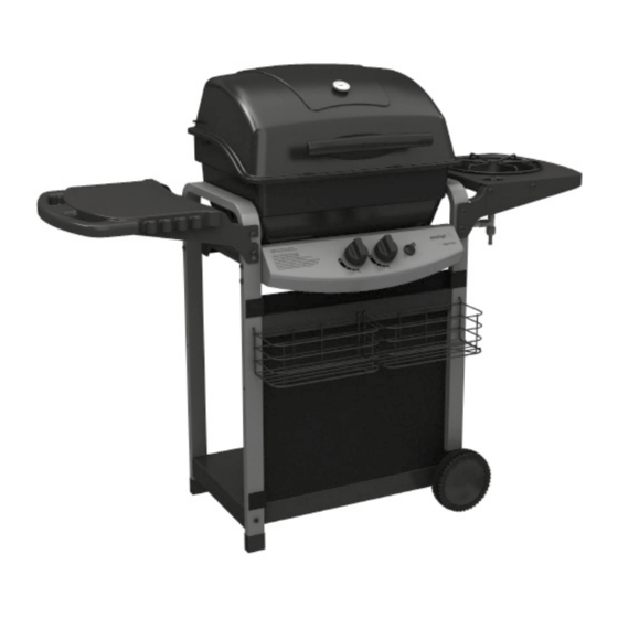
- Page 1 piùsaporillo G20513 · manuale d’uso · user manual · manuel utilisateur · manual de usuario · benutzerhandbuch...
- Page 2 Grazie per aver acquistato un barbecue Sochef ® per utilizzare al meglio questo prodotto, leggere con attenzione tutte le avvertenze e le istruzioni fornite nel presente manuale. Leggere e conservare il manuale per future consultazioni, anche se il barbecue è stato già...
- Page 3 AVVERTENZE DI 11. Per l’allacciamento del regolatore, 25. Non utilizzare il barbecue a gas seguire le istruzioni specifiche riportate SOCHEF® se gli allacciamenti del gas SICUREZZA nella sezione “Allacciamento e requisiti non hanno una tenuta perfetta. del regolatore”. La mancata osservanza dei messaggi 26.
- Page 4 KIT FERRAMENTA N° DESCRIZIONE CODICE QUANTITÀ ATTREZZI NECESSARI PER IL MONTAGGIO Vite da 1,4 -20UNC X50 20120-13050-250 • 2 Cacciavite a croce (lungo e corto) Vite da 1,4 -20UNC X35 20120-13035-250 • 2 Cacciavite a testa piatta da 1,4 (lungo e corto) Vite da 1,4 -20UNC X13 20120-13013-250 Vite NO.10-24UNC X10...
- Page 5 LISTA DEI COMPONENTI PER IL MODELLO #G20513 N° QUANTITÀ DESCRIZIONE CODICE Coperchio G205-0035-01 Maniglia coperchio G301-0042-02 Termostato G205-0003-01 Cerniera superiore G206-0002-01 Vano di cottura - camera di combustione G205-0010-01 Cerniera inferiore G205-0010-A2 Bruciatore G205-3200-01 Collettore G206-0014-02 Filo elettrico G206-0302-02 Griglia di cottura G205-0038-01 Griglia pietra lavica G206-0062-01...
- Page 6 SCHEMA ESTESO - MOD. #G20513 MANUALE PIETRA FERRAMENTA D’ASSEMBLAGGIO LAVICA...
- Page 7 ISTRUZIONI PER IL MONTAGGIO a. Fissare la gamba destra e sinistra del carrello (DB & DA) al supporto anteriore (DD), come mostrato in figura. OCCORRE: Vista posteriore - carrello barbecue a. Fissare il ripiano inferiore (DF) alle due estremità della gamba sinistra del carrello (DB), come mostrato in figura.
- Page 8 ISTRUZIONI PER IL MONTAGGIO d. Inserire i copriruota (DI) alle rotelle (DH). Vista posteriore - carrello barbecue a. Fissare il supporto posteriore (DE), i supporti del vano cottura (DC) alle gambe del carrello (DB & DA), come mostrato in figura. SUGGERIMENTO: Una persona deve mantenere in posizione corretta i sostegni del vano cottura, mentre la seconda procede al fissaggio dei perni.
- Page 9 ISTRUZIONI PER IL MONTAGGIO a. Fissare la valvola principale del gas (CD) al pannello di controllo (CA) attraverso i fori presenti sulla plancia di controllo. Nota: Assicurarsi che le terminazioni posteriori della valvola principale siano rivolte verso l’alto. OCCORRE: Vista posteriore - carrello barbecue b.
- Page 10 ISTRUZIONI PER IL MONTAGGIO MONTAGGIO VANO COTTURA a. Fissare le cerniere inferiori (BB) alla parte posteriore del vano cottura (BA), come mostrato in figura. Nota: Non stringere eccessivamente. OCCORRE: b. Inserire il bruciatore (BC), all’interno del vano di cottura (BA), con i tubi Venturi rivolti in avanti, ed il filo della valvola inserito nell’apposito foro.
- Page 11 ISTRUZIONI PER IL MONTAGGIO a. Fissare il vano cottura (BA) sui supporti inferiori (DC) precedentemente montati. OCCORRE: Nota: Prima di serrare le componenti assicurarsi che i tubi Venturi del bruciatore (BC) siano perfettamente inseriti alla valvola principale (CD). b. Collegare il filo elettrico (BD2) al dispositivo d’accensione (CC), come mostrato in figura.
- Page 12 ISTRUZIONI PER IL MONTAGGIO Inserire lo scudo termico (BH) sotto il vano cottura e fissarlo al supporto destro (DC), come mostrato in figura. Attenzione: bordi affilati, indossare guanti di sicurezza durante il montaggio. OCCORRE: Inserire il gancio per la vaschetta raccogli grasso (CH) alla parte inferiore del vano cottura (BA), come mostrato in figura.
- Page 13 ISTRUZIONI PER IL MONTAGGIO MONTAGGIO COPERCHIO a. Fissare il termostato (AC) al coperchio (AA). Nota: Montare il termostato (AC) dopo aver rimosso il dado di protezione, come mostrato in figura. b. Fissare le cerniere superiori (AD) al coperchio (AA). OCCORRE: c.
- Page 14 ISTRUZIONI PER IL MONTAGGIO Per collegare il coperchio (AA) al vano cottura (BA), posizionare le cerniere superiori (AD) all’interno di quelle inferiori (BB), e serrare i perni posizionati all’interno dei fori, come mostrato in figura. OCCORRE: MONTAGGIO RIPIANO LATERALE a. Fissare i supporti, anteriore e posteriore (EI &...
- Page 15 ISTRUZIONI PER IL MONTAGGIO MONTAGGIO FORNELLO LATERALE a. Fissare i supporti, anteriore e posteriore (EB & EC), all’alloggio del bruciatore (EA), come mostrato in figura. OCCORRE: b. Fissare l’alloggio del bruciatore assemblato (EA) all’esterno della gamba destra del carrello (DA), come mostrato in figura.
- Page 16 ISTRUZIONI PER IL MONTAGGIO a. Inserire il bruciatore (EE) attraverso il foro predisposto sul fondo del fornello (ED). Assicurarsi che il bruciatore laterale (EE) sia perfettamente inserito nella valvola del fornello (CF), come mostrato in figura. OCCORRE: b. Collegare l’estremità del filo elettrico (EF) al dispositivo d’accensione (CC), come mostrato in figura.
- Page 17 ISTRUZIONI PER IL MONTAGGIO a. Posizionare la manopola di comando (CB) sopra la valvola del bruciatore (CF). b. Posizionare la griglia di cottura del bruciatore laterale (EG) nell’appostito alloggio (EA). ATTENZIONE È consentito utilizzare pentole con un diametro non superiore a 22 e/o 24 cm. Fissare il telo frontale (DK) alle gambe del carrello attraverso gli strappi a velcro presenti negli angoli laterali.
- Page 18 ISTRUZIONI PER IL MONTAGGIO Fissare i cesti portaoggetti (DJ), alle gambe del carrello (DB & DA) e al supporto anteriore (DD) mediante gli appositi fori. SISTEMA DI COTTURA CON PIETRA LAVICA Questo barbecue è dotato di una griglia per pietra lavica ed una confezione della suddetta pietra (F3) da utilizzare per la cottura.
- Page 19 ISTRUZIONI PER IL MONTAGGIO Posizionare la griglia scaldavivande (BG) all’interno della camera di combustione, inserendo le estremità laterali all’interno del coperchio e le terminazioni cromate nei fori posizionati sul vano cottura.
- Page 20 (CG) del tubo di metallo per il fornello laterale (CE). (Seguire le avvertenze riportate nella sezione “Allacciamenti e requisiti del regolatore”) c. Fissare il regolatore di pressione alla valvola della bombola a gas. Attenzione: utilizzare solo kit regolatore del gas Sochef (non in dotazione) ®...
- Page 21 B a taratura fissa 30 mbar. attentamente le istruzioni prima di utilizzare il barbecue a gas SOCHEF®. • La lunghezza del tubo flessibile non • Con il primo assemblaggio, i tubi del gas ed i bruciatori saranno pieni deve superare 1,5 metri.
- Page 22 MANUTENZIONE E CURA • Verificare che non vi siano ostruzioni • Se il meccanismo di accensione degli orifizi della valvola del gas, dei non produce una scintilla, usare un tubicini dei fornelli e delle aperture dei fiammifero per accendere il fornello. Per prolungare la durata del Vostro fornelli.
- Page 23 Rimuovere il grasso in eccesso • Quando non si utilizza il barbecue utilizzando un raschietto in plastica. a gas SOCHEF®, chiudere il Lavare la vaschetta raccogli grasso collegamento alla bombola di gas con una soluzione di acqua e sapone, propano liquido.
- Page 24 • Cambiare il regolatore di pressione Puzza di gas • Regolatore di pressione non a norma e utilizzare kit regolatore di pressione Sochef® • I piedini della griglia sono assemblati in • I piedini della griglia sono regolabili. La griglia scaldavivande non si...
- Page 25 Risoluzione dei problemi per accensione elettrica PROBLEMA POSSIBILE CAUSA SOLUZIONE • Batteria non installata • Installare la batteria (assicurarsi correttamente che i poli + e – siano disposti in Nessuna scintilla quando si preme il • Batteria scarica maniera corretta) tasto di accensione;...
- Page 26 Thank for purchasing a Sochef grill. To use this ® product correctly, please read the warnings and instructions provided in this manual. Read and safe manual for future reference, even if the product has already been assembled by your local dealer.
- Page 27 DO NOT TOUCH ! all information of this manual. 9. Never place hands or fingers on the 25. Do not use SOCHEF barbecue ® front edge of the burner box when the unless gas regulator is properly grill is hot or the lid is open.
- Page 28 HARDWARE PACK N° DESCRIPTION PART NUMBER QUANTITY TOOLS NEEDED FOR ASSEMBLY 1,4” -20UNC X50 Screw 20120-13050-250 • #2 Phillips screwdriver (long and short) 1,4” -20UNC X35 Screw 20120-13035-250 • ¼” Slotted screwdriver (long and short) 1,4” -20UNC X13 Screw 20120-13013-250 NO.10-24UNC X10 Screw 20124-10010-250 •...
- Page 29 PARTS LIST FOR MODEL #G20513 N° QUANTITY DESCRIPTION PART NO Top lid assembly G205-0035-01 Top lid handle G301-0042-02 Thermometer G205-0003-01 Upper hinge G206-0002-01 Burner box assembly G205-0010-01 Lower hinge G205-0010-A2 Burner G205-3200-01 Collector box G206-0014-02 Electrode G206-0302-02 Cooking grate G205-0038-01 Lava rock plate G206-0062-01 Warming rack...
- Page 30 EXPLODED DIAGRAM FOR MODEL #G20513 HARDWARE ASSEMBLY LAVA PACK MANUAL ROCK...
- Page 31 ASSEMBLY INSTRUCTIONS a. Assemble the front brace (DD) to the left and right cart legs (DB & DA) as shown. YOU WILL NEED: View from the back of the cart assembly a. Assemble the bottom shelf (DF) to the bottom of the left cart leg (DB), as shown.
- Page 32 ASSEMBLY INSTRUCTIONS d. Insert the wheel caps (DI) into wheels (DH). View from the back of the cart assembly a. Assemble the rear brace (DE), the back left and right burner box support (DC) to the left and right cart legs (DB &...
- Page 33 ASSEMBLY INSTRUCTIONS a. Position the valve assembly (CD) through the back of the control panel (CA), and assemble. Note: Be sure that the back ending of the principale valve are upwards. YOU WILL NEED: View from the back of the cart assembly b.
- Page 34 ASSEMBLY INSTRUCTIONS BURNER BOX ASSEMBLY a. Assemble the lower hinge (BB) x 2 on the back of the burner box assembly (BA), as shown. Note: Do not over tigthen. YOU WILL NEED: b. Assemble the burner (BC) into the burner box assembly (BA), with the burner venturi tubes facing forward.
- Page 35 ASSEMBLY INSTRUCTIONS a. Position the burner box assembly (BA) onto the burner box supports (DC), as shown. YOU WILL NEED: NOTE: Before tightening the hardware, make sure the burner (BC) engages the valve assembly (CD). b. Attach the electrode wire (BD2) to the ignitor (CC), as shown.
- Page 36 ASSEMBLY INSTRUCTIONS Assemble the heat shield (BH) to the inside of the right burner box support (DC), as shown. Caution: sharp edges, wear safety gloves during assembly YOU WILL NEED: Hook the grease cup hook (CH) to the bottom of the burner box assembly (BA), as shown.
- Page 37 ASSEMBLY INSTRUCTIONS TOP LID ASSEMBLY a. Assemble the thermometer (AC) to the top lid (AA). Note: Remove the wing nut that is pre-assembled to the thermometer (AC) and then assembles, as shown. b. Assemble the upper hinge (AD) x2 to the top lid assembly (AA) YOU WILL NEED: c.
- Page 38 ASSEMBLY INSTRUCTIONS To assemble the top lid assembly (AA) to the burner box assembly (BA), position the upper hinges (AD) in between the lower hinges (BB), position hardware and lock into place, as shown. YOU WILL NEED: SIDE SHELF ASSEMBLY a.
- Page 39 ASSEMBLY INSTRUCTIONS SIDE BURNER TABLE ASSEMBLY a. Assemble the front and rear right side burner table brackets (EB & EC) to the right side burner table (EA), as shown. YOU WILL NEED: b. Assemble the right side burner table (EA) to the upper leg support bar (DA), as shown.
- Page 40 ASSEMBLY INSTRUCTIONS a. Position the side burner (EE) through the opening in the side burner drip pan (ED). Make sure the side burner (EE) engages the side burner valve (CF), and assembles, as shown. YOU WILL NEED: b. Attach the end of the side burner electrode (EF) to the ignitor(CC), as shown.
- Page 41 ASSEMBLY INSTRUCTIONS a. Position the side burner control knob (CB) over the side burner valve stem (CF). b. Place the side burner cooking grate (EG) into position on the right side burner table (EA). ATTENTION All pot or boiler that are used on side burner (EE) MUST BE with a diameter of 220 mm or 240 mm.
- Page 42 ASSEMBLY INSTRUCTIONS Attach the condiment basket (DJ) into the holes located at the front brace (DD), the left and right cart legs (DB & DA). LAVA ROCK COOKING SYSTEM This barbecue comes with a lava rock plate and a pack of lava rock (F3) for grilling.
- Page 43 ASSEMBLY INSTRUCTIONS To assemble the warming rack (BG), insert the stationary wire into the holes on the sides of the lid. Insert warming rack pivot legs into the holes on the inside of the burner box assembly, as shown. Stationary Wire Pivot Legs...
- Page 44 (CG) for the side burner (CE). (Follow the instructions in the section “Connection and regulator requirements). c. Attach the regulator coupling nut to the gas tank valve. Attention: use only pressure regulator kit SOCHEF (NOT INCLUDED) ®...
- Page 45 • When lighting the burner for the You are recommended to buy pressure LPG CYLINDER REQUIREMENTS regulator kit Sochef first time the tubes of the gas and the ® • Use only a 3 kg - 5 kg LPG cylinder.
- Page 46 IMPORTANT: Buy a SOCHEF ® cover removable containers. faster and with less energy. to protect your barbecue when not in Check the slide-out grease tray for use.
- Page 47 Regulator humming outside temperature or full cylinder Incomplete flame • Clean/replace burner • Plugged, leaky or rusted burner • Please replace and install a Sochef ® Gas smell • Pressure regulator not conform Pressure Regulator kit • The warming rack feet are adjustable.
- Page 48 • Use paper tissue to remove the dirt • Replace cracked or defective electrodes Warranty 1. Your Barbecue Sochef comes with a two-year warranty, which applies from the date of purchase. The warranty is limited to the barbecue or ®...
- Page 50 Sochef è un marchio ® SAL.MAR. S.r.l. Via Martiri di Nassiriya 84016 Pagani (SA) Italia...
Need help?
Do you have a question about the piusaporillo G20513 and is the answer not in the manual?
Questions and answers