
Related Manuals for Newport Vessels NK-180S

Summary of Contents for Newport Vessels NK-180S
- Page 1 Kayak Motor NK-180S User’s Manual Please read and retain this manual before using product...
-
Page 2: Table Of Contents
Contents 1 Product Overview . . . . . . . . . . . . . . . . . . . . . . . . . . . . . . . . . . . . . . . . . . 1.1 Product Identification . - Page 3 4.3.2 Setup With Control Cords at the Bottom . . . . . . . . . . . . . . 4.3.3 Inserting the Motor Supporting Drum in the Bracket .
- Page 4 6.6 Tilting the Motor . . . . . . . . . . . . . . . . . . . . . . . . . . . . . . . . . . . . . . . . 6.7 Finishing the Trip .
-
Page 5: Product Overview
Product Overview The Kayak Motor NK-180S is designed using the latest DC motor technology and optimized to deliver high efficiency in a compact package. The propulsive power of the NK-180S is roughly equivalent to a 1.8hp petrol outboard motor, but with silent and emission free power delivery. -
Page 6: Included In Your Box
1.2 Included in Your Box Here is what should be included in your Kayak Motor NK-180S. Please contact us directly if something is missing from this list of contents. Items Figure Motor Unit 1 pc Controller 1 pc Motor Mount... - Page 7 Items Figure Steering Triangle 1 pc Clamp Ring 1 pc Cable Handle 2 pcs Emergency Stop Key 2 pcs Swing Arm 1 pc S Biner 2 pcs Stainless Biner 2 pcs Battery Extention Cable 1 set Nylon Cable 1 set Steering Cable 1 set Installation Kit...
-
Page 8: Parts And Diagrams
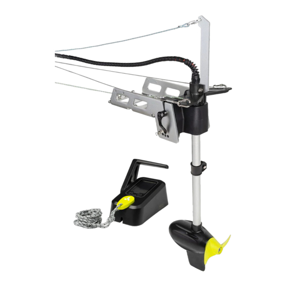
1.3 Parts and Diagrams 1.3.1 Motor and Bracket S Biner and cord Swing arm for lifting the motor S Biner and cord Battery and control for reverse lock box connection Steering triangle Handle Motor supporting drum Aluminum bracket Clamping ring Quick release axle with handle Motor shaft... -
Page 9: Speed Controller
1.3.2 Speed Controller Screen display Power button Accelerator lever Emergency Battery type stop key selection button... -
Page 10: Technical Data
Technical Data Specification Rated Input Power(static) 600W/25A Comparable Petrol Outboard 1.8 HP • Deep cycle marine battery Battery Type • LFP lithium battery • Lithium cobalt oxide battery • 24V-Deep cycle marine battery Battery Input voltage • 24V-LFP Lithium battery •... -
Page 11: Safety Information
Safety Information 3.1 Critical Safety Information Please read all safety information before installing or operating your electric motor. Severe injury, damage, or even death can occur as a result of improper usage. There is a risk of death or severe injury from electric shock- use caution and do not touch any uninsulated wires or damaged parts. - Page 12 There is inherent danger in using a boat- always prepare for the unexpected. A boat which is out of control can easily result in severe injuries or death by drowning. ‹ Always check weather predictions and water conditions before a trip on the water, and also familiarize yourself with a map of the area you’ll be traversing.
-
Page 13: Before Use
Parts may be hot enough to cause burns. Do not touch the components or battery immediately after use; allow to cool sufficiently before handling the components. Danger of crushing when tilting the motor- keep fingers, hands, and all body parts away from mechanical parts and the area of the motor when tilting the motor. -
Page 14: After Use
3.4 After Use • Disconnect the motor from the battery after use. • Flush the motor carefully with freshwater after each usage, especially after use in saltwater. • Do NOT carry the kayak/boat by lifting with the bracket. This can cause damage to the boat and potentially to the bracket. -
Page 15: Installation With Drilling Holes Using A Template
2. Place four M8 screws and four washers over the threaded inserts, as shown in the diagram above, and tighten the screws to mount the bracket. Make sure the screws are tightened and the bracket is flush and secure. NOTE: We recommend applying torque of 140 lbft (16Nm) to the screws. -
Page 16: Installation With An Adapting Plate
Different kayaks may require different installation hardware. If your kayak requires installation hardware other than what is included in this kit, please find it at your local hardware store. Newport Vessels does not carry every possible hardware combination necessary to fit all brands and models of kayaks;... -
Page 17: Installation Of The Motor Propeller
4.2 Installation of the Motor Propeller Washer Drive pin Propeller Hexagonal nut Before installing the propeller, make sure the battery is disconnected from the motor, then follow the steps below to finish the setup: 1. Insert the drive pin into the small hole on the motor output shaft. 2. -
Page 18: Setting Up Your Steering
4.3 Setting up Your Steering Kayaks feature many different cable routing systems,while some more basic models have no cable routing. To add cable routing to your particular boat, contact the boat manufacturer for recommendations. Kayak cable routing can generally be broken down into two categories:cables routed above the deck of the kayak, and cables routed below the deck of the kayak. -
Page 19: Setup With Control Cords At The Top
4.3.1 Setup With Control Cords at the Top If you have a kayak setup with control cords running on the top of the kayak, follow the steps below to finish the motor control cords setup: Swing arm Steering triangle M6 nut M6 screw Washer 1. - Page 20 Swing arm Steering triangle Direction cords at the top Motor supporting drum Motor shaft Clamping ring 3. Slide the preassembled clamping ring onto the motor shaft. 4. Insert the motor shaft into the motor supporting drum with the clamping ring below the drum, as shown. 5.
-
Page 21: Setup With Control Cords At The Bottom
4.3.2 Setup With Control Cords at the Bottom If the kayak control cords come out under the position of the supporting drum, follow the steps below to finish the motor control cords setup: Swing arm Clamping ring M6 screw Washer M6 nut 1. - Page 22 Swing arm Clamping ring Motor supporting drum Steering triangle Direction cords Motor shaft at the bottom 3. Slide the preassembled steering triangle onto the motor shaft. 4. Insert the motor shaft into the motor supporting drum as shown. 5. Slide the preassembled clamping ring onto the motor shaft above the supporting drum as shown.
-
Page 23: Inserting The Motor Supporting Drum In The Bracket
4.3.3 Inserting the Motor Supporting Drum in the Bracket Quick release axle 1. The quick release axle should be preinstalled in the motor supporting drum. 2. Insert the motor supporting drum into the bracket. 3. Adjust the knob on the quick release axle so that the lever can be opened or closed with firm hand pressure. -
Page 24: Adjusting Motor Depth Of Water After Setup
4.3.4 Adjusting Motor Depth of Water After Setup 1. Hold the motor firmly and loosen the screw on either the clamping ring or the steering triangle, whichever is topmost on the shaft in your set up. 2. Adjust shaft position to find the optimum motor depth in water. 3. -
Page 25: Cable To Perform Reverse Lock
3. There are four options for steering sensitivity. Attaching the cable to the outer holes will mean direction changes happen more gradually,while attaching it to the inner holes will make direction changes more sudden. It is recommended that you start by hooking the stainless steel biner to the outermost holes. -
Page 26: Cable To Lift The Motor
5. Place the end of the cable where you can access it easily. 6. You may choose to create a dedicated guide for this cable near the handle location as well. See www.newportvessels.com/kayak- steering-accessories/ for more products. 4.3.5.3 Cable to Lift the Motor Cord to lift the motor Cable guide 1. -
Page 27: Complete The Cord Setup
4.4 Complete the Cord Setup This is the overall setup of the motor after all control cables have been installed. Motor lift cord Cords to control Reverse lock the direction cord... -
Page 28: Using External Steering System
4.5 Using External Steering System If you are planning on using the motor only for forward/reverse propulsion and are using other methods to steer such as a paddle, you can fix the motor direction with the following steps: Fixing pin 1. -
Page 29: Adjust The Motor Trim Angle
4.6 Adjust the Motor Trim Angle You can adjust the angle between water surface and the motor using the motor trim angle adjustment design. Follow the steps below if you would like to change the angle of the motor. Cotter pin Trim rod Four trim positions... -
Page 30: Connect To The Speed Controller
4.7 Connect to the Speed Controller 1. Find the signal cable coming from the motor shaft and connect it to the speed controller. Make sure the cable is tightly connected. 2. It is recommended to fit the cable into the cable tidy slot underneath of the speed controller. -
Page 31: Controller Display
4. Tighten the connection of the battery cables to the battery terminals. Make sure the connection is solid and secure. Controller Display 5.1 Overview of Multi-Function Display Battery Battery voltage percentage display display Battery type Throttle display percentage display Power input display Battery type Power button... -
Page 32: Battery Display
5.2 Battery Display 5.2.1 Estimated Percent of Remaining Battery Power Battery percentage display 100% <20% The battery icon has 6 different status levels to display the estimated remaining battery percentage. If the battery power is less than 20%, the battery icon will flash to remind the user to recharge the battery. Do not overestimate the remaining battery range;... -
Page 33: Switching Between Battery Types
5.2.2 Switching Between Battery Types Battery type display Battery type selection button This motor can run on a 24V deep cycle battery setup, a 24V LFP lithium battery setup, or a 25.9V lithium cobalt oxide battery. You will need to select which type of battery you are using with your motor for accurate results on the LCD screen. -
Page 34: Error Status Display
5.3 Error Status Display Motor over voltage Motor over heated Motor stalled The icons indicated on the LCD screen above show three possible error statuses of the motor. When a fault occurs, there will be a corresponding code on screen to help diagnose the problem. See section 5.4 Error Codes and Solutions. -
Page 35: Error Codes And Solutions
5.4 Error Codes and Solutions If there is an issue with the motor function, the display will show an error code to help diagnose the problem and find the solution. If the motor is not operating under normal condition, the error code will be displayed here. - Page 36 Error Description Solution Code This indicates the battery voltage is Motor is undervoltage low. Recharge the battery. The voltage of the battery is too Motor is overvoltage high for the motor. Use a compatible battery. The motor is likely tangled by fishing lines, weeds, or other obstructions.
-
Page 37: Operation
Operation 6.1 Start the Motor Magnetic emergency stop key Speed control handle To start the motor please follow the steps below: When the battery is connected, the screen will light up automatically If emergency stop key is removed, the screen will have this display and continuously... - Page 38 When power button is on, When power button is o , this throttle percentage display this throttle percentage display will show current throttle will be unavailable percentage 1. Place the magnet kill switch on the speed controller. The screen should look like the display on the left. 2.
-
Page 39: Travel Forward/Reverse
6.2 Travel Forward/Reverse The motor’s forward/reverse motion is controlled by the accelerator lever on the speed controller. Please refer to the diagram below which demonstrates how to operate. Forward Neutral Reverse When switching to reverse, please pull the reverse lock cable to lock the motor and prevent it from tilting up and out of the water. -
Page 40: Steering The Motor
6.3 Steering the Motor While the motor is operating, pull the steering cords to control the kayak/boat’s direction. Pull the left cable Pull the right cable to turn left to turn right To make the kayak/boat turn left, pull the left cord on the steering triangle. -
Page 41: Emergency Stop
6.4 Emergency Stop Remove the magnetic emergency stop key Move the handle to the neutral position To stop immediately you can: Pull off the magnetic emergency stop switch from the speed controller to stop the motor. Move the accelerator lever on the speed controller to neutral to stop the motor. -
Page 42: Stopping The Motor
6.5 Stopping the Motor To stop the motor, follow the steps below: 1. Move the accelerator lever on the speed controller to the neutral position. 2. Press the On/Off button on the speed controller. 3. Remove the emergency kill switch. 6.6 Tilting the Motor When needed, the motor can be tilted up to stow away or to avoid underwater obstacles. -
Page 43: Finishing The Trip
6.7 Finishing the Trip When the trip is finished, please disconnect the motor from the battery and take the motor out of water. If the motor was used in the saltwater, thoroughly rinse the motor with fresh water. This will help prevent corrosion and salt buildup. -
Page 44: Remove The Motor From The Kayak
6.9 Remove the Motor From the Kayak It is very easy to remove the motor from the bracket for travel, however you will want to leave the mount installed. Follow the steps below: 1. Move the accelerator lever to the neutral position, and turn off the motor. -
Page 45: Care And Service
Care and Service 7.1 Care of Motor Components • Please regularly follow all maintenance tips to keep your motor in optimal working condition. • Do not start the motor in shallow water as it may damage the propeller. • After each use, check between the plastic propeller and metal motor housing for fishing line, weeds, or other debris. -
Page 46: Replacing The Fin
7.4 Replacing the Fin You can replace the fin component when it is damaged. To do this, follow the steps below: M3 nut M3 screw 1. Release the two M3 screws and nuts. 2. Remove the old fin component. 3. Insert the new fin component. 4. -
Page 47: Customer Support
Customer Support If you have questions that are not answered in this manual or your troubleshooting is not successful, please contact Newport Vessels! Our California based customer service team is standing by to assist you. Customer Support Phone: (866)721-0002 E-mail: support@newportvessels.com...
Need help?
Do you have a question about the NK-180S and is the answer not in the manual?
Questions and answers