
Related Manuals for Yamaha YZ125 2021


Summary of Contents for Yamaha YZ125 2021
- Page 1 2021 OWNER’S SERVICE MANUAL YZ125 Read this manual carefully before operating this vehicle. YZ125M2 LIT-11626-34-27 B0V-2819U-10...
- Page 2 EAM20161 Read this manual carefully Operating, servicing and maintaining a passenger vehicle or off-road vehicle can expose you to chemicals including engine exhaust, carbon monoxide, phthalates, and lead, which are known to the State of California to cause cancer and birth defects or other reproductive harm.
- Page 3 EAM20080 YZ125M2 OWNER’S SERVICE MANUAL ©2021 by Yamaha Motor Corporation, U.S.A. First edition, April 2020 All rights reserved. Any reproduction or unauthorized use without the written permission of Yamaha Motor Corporation, U.S.A. is expressly prohibited. P/N. LIT-11626-34-27...
- Page 4 EAM20180 IMPORTANT Congratulations on your purchase of a Yamaha YZ series. This model is the culmination of Yamaha’s vast experience in the production of pacesetting racing machines. It represents the highest grade of craftsmanship and reliability that have made Yamaha a leader.
- Page 5 EAM20162 YAMAHA MOTOR CORPORATION, U.S.A. YZ MOTORCYCLE LIMITED WARRANTY...
- Page 6 EAM20082 HOW TO USE THIS MANUAL In this manual, descriptions of installation, removal, disassembly, assembly, check, and adjustment procedures are laid out with the individual steps in sequential order. • The manual is divided into chapters and each chapter is divided into sections. The current section title “1”...
- Page 7 EAM20083 SYMBOLS The following symbols are used in this manual for easier understanding. The following symbols are not relevant to every vehicle. SYMBOL DEFINITION SYMBOL DEFINITION Serviceable with engine mounted Gear oil Filling fluid Molybdenum disulfide oil Lubricant Brake fluid Special tool Wheel bearing grease Tightening torque...
-
Page 9: Table Of Contents
TABLE OF CONTENTS EAM10003 GENERAL INFORMATION SPECIFICATIONS PERIODIC CHECKS AND ADJUSTMENTS CHASSIS ENGINE COOLING SYSTEM FUEL SYSTEM ELECTRICAL SYSTEM TROUBLESHOOTING TUNING... - Page 11 GENERAL INFORMATION SAFETY INFORMATION ..................1-1 FOR SAFETY, BE SURE TO OBEY THE FOLLOWING:......1-1 LOCATION OF IMPORTANT LABELS.............1-4 DESCRIPTION....................1-5 IDENTIFICATION ....................1-6 VEHICLE IDENTIFICATION NUMBER ............1-6 ENGINE SERIAL NUMBER................1-6 INCLUDED PARTS ...................1-7 SIDESTAND ....................1-7 NIPPLE WRENCH ..................1-7 VALVE JOINT .....................1-7 COLLAR (tool for YPVS) ................1-7 IMPORTANT INFORMATION ................1-8 PREPARATION FOR REMOVAL AND DISASSEMBLY ......1-8 REPLACEMENT PARTS ................1-8...
- Page 12 MAINTENANCE AFTER BREAK-IN ..............1-20 MAJOR MAINTENANCE ................1-20 AIR FILTER MAINTENANCE ..............1-20 TORQUE-CHECK POINTS................1-21 MOTORCYCLE CARE AND STORAGE............1-23 CARE ......................1-23 STORAGE ....................1-24...
-
Page 13: Safety Information
Yamaha ma- accidents. Many accidents have been chine, and take care to maintain it properly and caused by an automobile driver who did not operate it safely. - Page 14 1. Always wear an approved helmet. Yamaha can neither endorse nor recommend 2. Wear a face shield or goggles. Wind in your the use of accessories not sold by Yamaha or unprotected eyes could contribute to an im- modifications not specifically recommended by...
- Page 15 SAFETY INFORMATION Aftermarket Tires and Rims The tires and rims that came with your motorcy- cle were designed to match the performance ca- pabilities and to provide the best combination of handling, braking, and comfort. Other tires, rims, sizes, and combinations may not be appropriate. Refer to “CHECKING THE TIRES”...
-
Page 16: Location Of Important Labels
LOCATION OF IMPORTANT LABELS EAM20085 LOCATION OF IMPORTANT LABELS Please read the following important labels carefully before operating this vehicle. 3, 4... -
Page 17: Description
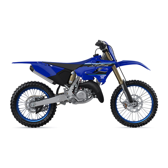
DESCRIPTION EAM20086 DESCRIPTION 13 14 15 11 10 11.Check bolt (Transmission oil level) 1. Clutch lever 12.Rear brake pedal 2. Engine stop switch 13.Valve joint 3. Front brake lever 4. Throttle grip 14.Fuel cock 15.Air filter 5. Radiator cap 6. Fuel tank cap 16.Drive chain 17.Shift pedal 7. -
Page 18: Identification
There are two significant reasons for knowing the serial number of your vehicle: 1. When ordering parts, you can give the num- ber to your Yamaha dealer for positive identi- fication of the model you own. 2. If your vehicle is stolen, the authorities will need the number to search for and identify your vehicle. -
Page 19: Included Parts
INCLUDED PARTS EAM20088 INCLUDED PARTS EAM30372 SIDESTAND This sidestand “1” is used to support only the machine when standing or transporting it. EWA20260 WARNING • Never apply additional force to the sides- tand. • Remove this sidestand before starting out. EAM30615 COLLAR (tool for YPVS) This collar “1”... -
Page 20: Important Information
2. Use proper special tools and equipment. Re- used for repair of the vehicle, including periodic fer to “SPECIAL TOOLS” on page 1-12. replacement parts, are new YAMAHA genuine parts and recommended parts. Do not use any used parts, because these may... -
Page 21: Lock Washers/Plates And Cotter Pins
IMPORTANT INFORMATION 1. Oil 2. Lip 3. Spring 4. Grease EAM30012 LOCK WASHERS/PLATES AND COTTER PINS After removal, replace lock washers/plates “1” and cotter pins with new ones. After the bolt or nut has been tightened to specification, firmly bend the lock tabs along a flat of the bolt or nut. EAM30014 CIRCLIPS When assembling parts, always use new cir-... -
Page 22: Basic Service Information
BASIC SERVICE INFORMATION • There are many types of coupler locks; EAM20120 BASIC SERVICE INFORMATION therefore, be sure to check the type of cou- pler lock before disconnecting the coupler. EAM30181 ELECTRICAL SYSTEM Checking the electrical system ECA14371 NOTICE Never insert the tester probes into the cou- pler terminal slots. - Page 23 BASIC SERVICE INFORMATION • If the pin “1” on the terminal is flattened, bend it up. • After disassembling or assembling a coupler, pull on the leads to make sure that they are in- stalled securely. 5. Check: • No continuity Digital circuit tester (CD732) 90890-03243 Model 88 Multimeter with tachom-...
-
Page 24: Special Tools
SPECIAL TOOLS EAM20121 SPECIAL TOOLS The following special tools are required for accurate and complete adjustment and assembly. Using the correct special tool will help prevent damage caused by the use of improper tools or improvised tech- niques. The shape and tool number used for the special tool differ by country, so two types are provid- ed. - Page 25 SPECIAL TOOLS Reference Tool name/Tool No. Illustration pages Piston pin puller set 90890-01304 Piston pin puller YU-01304 YU-01304 Rotor holding tool 5-16, 5-17 90890-01235 Universal magneto and rotor holder YU-01235 Flywheel puller 5-16 90890-01189 Flywheel puller YM-01189 Universal clutch holder 5-28, 5-30 90890-04086 Universal clutch holder...
- Page 26 SPECIAL TOOLS Reference Tool name/Tool No. Illustration pages Crankcase separating tool 5-37, 5-41 90890-01135 Crankcase separator YU-01135-B Yamaha bond No. 1215 5-38 90890-85505 Three bond No. 1215® Crankshaft installer pot 5-38, 5-41 90890-01274 Installing pot YU-90058 YU-90058/YU-90059 Crankshaft installer bolt...
- Page 27 SPECIAL TOOLS Reference Tool name/Tool No. Illustration pages Radiator cap tester 6-3, 6-3 90890-01325 Mityvac cooling system tester kit YU-24460-A YU-24460-A Radiator cap tester adapter 6-3, 6-3 90890-01352 Pressure tester adapter YU-33984 YU-33984 Fuel level gauge adapter 7-10 90890-01470 Fuel level gauge adapter YM-01470 Fuel level gauge 7-10...
-
Page 28: Instrument And Control Functions
INSTRUMENT AND CONTROL FUNCTIONS EAM20181 INSTRUMENT AND CONTROL FUNCTIONS EAM30182 ENGINE STOP SWITCH The engine stop switch “1” is located on the left handlebar. Continue pushing the engine stop switch till the engine comes to a stop. EAM30188 FRONT BRAKE LEVER The front brake lever “1”... -
Page 29: Starter Knob (Choke)
INSTRUMENT AND CONTROL FUNCTIONS in this position. EAM30444 STARTER KNOB (CHOKE) When cold, the engine requires a richer air-fuel mixture for starting. A separate starter circuit, which is controlled by the starter knob “1”, sup- plies this mixture. Pull the starter knob out to open the circuit for starting. -
Page 30: Starting And Break-In
STARTING AND BREAK-IN 4. Run the engine at idle or slightly higher until it EAM20123 STARTING AND BREAK-IN warms up: this usually takes about one or two minutes. EAM30538 5. The engine is warmed up when it responds FUEL AND ENGINE MIXING OIL normally to the throttle with the starter knob Mix oil with the gas at the ratio specified below. - Page 31 STARTING AND BREAK-IN ECA25821 NOTICE After a break-in or after each race, always check the points shown in “TORQUE- CHECK POINTS” for tightening torques and retighten them. Also when the following parts are replaced, a break-in is required. • Cylinder and Crankshaft: A break-in is re- quired for about an hour.
-
Page 32: Maintenance After Break-In
Disassemble the carburetor and clean the AIR FILTER MAINTENANCE small holes, blowing them with compressed Apply the Yamaha foam air filter oil or other qual- air. ity foam air filter oil to the element. (Excess oil in • CDI magneto... -
Page 33: Torque-Check Points
TORQUE-CHECK POINTS EAM20125 TORQUE-CHECK POINTS Frame construction Combined seat and fuel tank Fuel tank to frame Frame to rear frame Engine mounting Frame to engine Engine bracket to engine Engine bracket to frame Seat Seat to frame Steering Steering stem to handlebar Steering stem to frame Steering stem to upper bracket Upper bracket to handlebar... - Page 34 TORQUE-CHECK POINTS Plastic cover Tightening of front fender Tightening of fork leg protector Tightening of air scoop Left cover to rear frame Tightening of side cover Tightening of rear fender Tightening of mud flap Tightening of rear brake disc cover Tightening of rear brake caliper cover Concerning the tightening torque, refer to “TIGHTENING TORQUES”...
-
Page 35: Motorcycle Care And Storage
MOTORCYCLE CARE AND STORAGE ucts are used on hard-to-remove dirt, do EAM20126 MOTORCYCLE CARE AND STOR- not leave the cleaner on the affected area any longer than instructed. Also, thorough- ly rinse the area off with water, immediately dry it, and then apply a corrosion protec- EAM30200 CARE tion spray. -
Page 36: Storage
Salt sprayed on roads in the winter may remain well into spring. • Consult a Yamaha dealer for advice on what 1. Clean the motorcycle with cold water and a products to use. - Page 37 MOTORCYCLE CARE AND STORAGE stored. Long-term Before storing your motorcycle for several months: 1. Follow all the instructions in “CARE” on page 1-23. 2. Drain the fuel tank, fuel lines, and the carbu- retor float bowl. 3. Perform the following steps to protect the cyl- inder, piston rings, etc.
- Page 38 MOTORCYCLE CARE AND STORAGE 1-26...
-
Page 39: Specifications
SPECIFICATIONS GENERAL SPECIFICATIONS ................2-1 ENGINE SPECIFICATIONS................2-2 CHASSIS SPECIFICATIONS................2-5 ELECTRICAL SPECIFICATIONS..............2-8 TIGHTENING TORQUES..................2-9 GENERAL TIGHTENING TORQUE SPECIFICATIONS ......2-9 ENGINE TIGHTENING TORQUES ............2-10 CHASSIS TIGHTENING TORQUES ............2-11 CABLE ROUTING DIAGRAM ................2-15... -
Page 40: General Specifications
GENERAL SPECIFICATIONS EAM20127 GENERAL SPECIFICATIONS Model Model B0VA Dimensions Overall length 2135 mm (84.1 in) Overall width 825 mm (32.5 in) Overall height 1295 mm (51.0 in) Seat height 975 mm (38.4 in) Wheelbase 1445 mm (56.9 in) Ground clearance 365 mm (14.37 in) Weight Curb weight... -
Page 41: Engine Specifications
ENGINE SPECIFICATIONS EAM20128 ENGINE SPECIFICATIONS Engine Combustion cycle 2-stroke Cooling system Liquid cooled Induction system Reed valve Displacement 125 cm³ Number of cylinders Single cylinder Bore stroke 54.0 54.5 mm (2.13 2.15 in) Compression ratio 8.6–10.7 : 1 Starting system Kickstarter Fuel... - Page 42 3.692 (48/13) Final drive Chain Air filter Air filter element Wet element Air filter oil grade Yamaha foam air filter oil or other quality foam air filter oil Carburetor Type quantity TMXx38 1 ID mark 1C37 51 Main jet...
- Page 43 ENGINE SPECIFICATIONS Reed valve Thickness 0.470 mm (0.0185 in) Valve stopper height 8.2–8.6 mm (0.32–0.34 in) Valve bending limit 0.2 mm (0.01 in)
- Page 44 CHASSIS SPECIFICATIONS EAM20129 CHASSIS SPECIFICATIONS Chassis Frame type Semi double cradle 26.0 Caster angle Trail 109 mm (4.3 in) Front wheel Wheel type Spoke wheel Rim size 21 x 1.60 Radial wheel runout limit 2.0 mm (0.08 in) Lateral wheel runout limit 2.0 mm (0.08 in) Wheel axle bending limit 0.50 mm (0.02 in)
- Page 45 Fork spring free length limit 449.0 mm (17.68 in) Inner tube bending limit 0.2 mm (0.01 in) Recommended oil Yamaha Suspension Oil S1 Quantity (left) 510.0 cm³ (17.24 US oz, 17.99 Imp.oz) Quantity (right) 510.0 cm³ (17.24 US oz, 17.99 Imp.oz)
-
Page 46: Chassis Specifications
CHASSIS SPECIFICATIONS Adjustment value from the start position (Soft) Adjustment value from the start position 1-3/8 (STD) Adjustment value from the start position (Hard) Slow compression damping Unit for adjustment Click Adjustment value from the start position (Soft) Adjustment value from the start position (STD) Adjustment value from the start position (Hard) -
Page 47: Electrical Specifications
ELECTRICAL SPECIFICATIONS EAM20130 ELECTRICAL SPECIFICATIONS Ignition system Ignition system Ignition timing (B.T.D.C.) 0.50 mm (0.02 in) 248.0–372.0 Pickup coil resistance 720.0–1080.0 Charging coil 1 resistance 44.0–66.0 Charging coil 2 resistance Ignition coil 0.24–0.36 Primary coil resistance Secondary coil resistance 5.68–8.52 k... -
Page 48: Tightening Torques
TIGHTENING TORQUES EAM20131 TIGHTENING TORQUES EAM30205 GENERAL TIGHTENING TORQUE SPECIFICATIONS This chart specifies tightening torques for stan- dard fasteners with a standard ISO thread pitch. Tightening torque specifications for special com- ponents or assemblies are provided for each chapter of this manual. To avoid warpage, tight- en multi-fastener assemblies in a crisscross pat- tern and progressive stages until the specified tightening torque is reached. -
Page 49: Engine Tightening Torques
TIGHTENING TORQUES EAM30203 ENGINE TIGHTENING TORQUES - marked portion shall be checked for torque tightening after break-in or before each race. Thread Item Q’ty Tightening torques Remarks size Spark plug M14S 20 N·m (2.0 kgf·m, 15 lb·ft) Cylinder head nut 28 N·m (2.8 kgf·m, 21 lb·ft) Cylinder head stud bolt 13 N·m (1.3 kgf·m, 9.6 lb·ft) -
Page 50: Chassis Tightening Torques
TIGHTENING TORQUES Thread Item Q’ty Tightening torques Remarks size Oil check bolt 10 N·m (1.0 kgf·m, 7.4 lb·ft) Oil drain bolt 20 N·m (2.0 kgf·m, 15 lb·ft) Kickstarter lever 10 N·m (1.0 kgf·m, 7.4 lb·ft) Clutch cover bolt 10 N·m (1.0 kgf·m, 7.4 lb·ft) Primary drive gear bolt 48 N·m (4.8 kgf·m, 35 lb·ft) Use a lock... - Page 51 TIGHTENING TORQUES Thread Item Q’ty Tightening torques Remarks size Inner tube and adjuster 55 N·m (5.5 kgf·m, 41 lb·ft) Base valve (front fork) 29 N·m (2.9 kgf·m, 21 lb·ft) Adjuster (damper assembly) 29 N·m (2.9 kgf·m, 21 lb·ft) Bleed screw (front fork) 1.3 N·m (0.13 kgf·m, 0.95 lb·ft) Front fork protector bolt 5 N·m (0.5 kgf·m, 3.7 lb·ft)
- Page 52 TIGHTENING TORQUES Thread Item Q’ty Tightening torques Remarks size Nipple (spoke) — 2.5 N·m (0.25 kgf·m, 1.8 lb·ft) Rear wheel sprocket nut 42 N·m (4.2 kgf·m, 31 lb·ft) Rear brake disc cover bolt 10 N·m (1.0 kgf·m, 7.4 lb·ft) ...
- Page 53 TIGHTENING TORQUES Thread Item Q’ty Tightening torques Remarks size Screw (mud flap) — 1.3 N·m (0.13 kgf·m, 0.95 lb·ft) Side cover bolt 7 N·m (0.7 kgf·m, 5.2 lb·ft) Seat bolt 19 N·m (1.9 kgf·m, 14 lb·ft) Number plate bolt 7 N·m (0.7 kgf·m, 5.2 lb·ft) ...
-
Page 54: Cable Routing Diagram
CABLE ROUTING DIAGRAM EAM20152 CABLE ROUTING DIAGRAM Frame and engine (left side view) 2-15... - Page 55 CABLE ROUTING DIAGRAM M. Direct the clip with its finger grip facing for- 1. Engine stop switch lead ward. 2. Throttle cable N. Tighten the clamp with its bolt head facing 3. Clutch cable the left side of the chassis (on both sides of 4.
- Page 56 CABLE ROUTING DIAGRAM Frame and engine (right side view) 2-17...
- Page 57 CABLE ROUTING DIAGRAM 1. High tension cord 2. Engine stop switch lead 3. Ignition coil lead 4. Clamp 5. CDI unit 6. CDI unit band 7. Joint connector 8. Radiator breather hose 9. CDI magneto lead 10.Connector cover 11.Throttle cable 12.Clutch cable 13.CDI unit stay A.
- Page 58 CABLE ROUTING DIAGRAM Handlebar (front view) 2-19...
- Page 59 CABLE ROUTING DIAGRAM 1. Brake hose 2. Master cylinder 3. Engine stop switch lead 4. Engine stop switch 5. Throttle cable 6. Clutch cable 7. Clamp 8. Cable guide A. Install the brake hose so that its pipe portion directs as shown and lightly touches the pro- jection on the master cylinder.
- Page 60 CABLE ROUTING DIAGRAM Rear brake (right side view) 2-21...
- Page 61 CABLE ROUTING DIAGRAM 1. Master cylinder 2. Brake hose holder 3. Brake hose A. Pass the brake hose into the brake hose holders. B. If the brake hose contacts the rear shock absorber spring, correct its twist. C. Install the brake hose so that its pipe portion directs as shown and lightly touches the pro- jection on the master cylinder.
- Page 62 CABLE ROUTING DIAGRAM 2-23...
-
Page 63: Periodic Checks And Adjustments
PERIODIC CHECKS AND ADJUSTMENTS MAINTENANCE INTERVALS ................3-1 MAINTENANCE INTERVALS..............3-1 PRE-OPERATION INSPECTION AND MAINTENANCE .........3-4 GENERAL INSPECTION AND MAINTENANCE ........3-4 ENGINE......................3-5 ADJUSTING THE PILOT AIR SCREW ............3-5 CHECKING THE ENGINE IDLING SPEED..........3-5 CHECKING THE THROTTLE GRIP ............3-5 CHECKING THE SPARK PLUG..............3-5 CHECKING THE TRANSMISSION OIL LEVEL .........3-6 CHANGING THE TRANSMISSION OIL .............3-6 ADJUSTING THE CLUTCH LEVER FREE PLAY ........3-7... - Page 64 CHECKING AND LUBRICATING THE CABLES........3-24 LUBRICATING THE BRAKE LEVER ............3-24 LUBRICATING THE CLUTCH LEVER .............3-24 LUBRICATING THE PEDAL..............3-24 ELECTRICAL SYSTEM..................3-25 CHECKING THE IGNITION TIMING ............3-25...
-
Page 65: Maintenance Intervals
(e.g., rain, dirt, etc.). Therefore, earlier inspection is required by reference to the list below. Items marked with an asterisk should be performed by a Yamaha dealer as they require special tools, data and technical skills. - Page 66 • Replace. • Check chain slack, alignment and condition. • Adjust and thoroughly lubricate 16 * Drive chain chain with Yamaha chain and cable lube or equivalent. • Replace. • Check coolant level and for leak- ...
- Page 67 MAINTENANCE INTERVALS Every race Every third Every fifth After Item Routine (about race (about race (about As required break-in 2.5 hours) 7.5 hours) 12.5 hours) • Check operation and adjust. • Tighten if necessary. • Lubricate with lithium-soap-based ...
-
Page 68: Pre-Operation Inspection And Maintenance
PRE-OPERATION INSPECTION AND MAINTENANCE EAM20134 PRE-OPERATION INSPECTION AND MAINTENANCE Before riding for break-in operation, practice or a race, make sure the machine is in good operating con- dition. Before using this machine, check the following points. EAM30209 GENERAL INSPECTION AND MAINTENANCE Item Inspect Page... -
Page 69: Engine
ENGINE EAM20135 EAM30475 ENGINE CHECKING THE THROTTLE GRIP Prior to adjusting throttle grip free play, the en- EAM30607 ADJUSTING THE PILOT AIR SCREW gine idling speed should be adjusted. 1. Adjust: 1. Check: • Pilot air screw “1” • Throttle grip free play “a” Out of specification ... -
Page 70: Checking The Transmission Oil Level
ENGINE utes and wait for five minutes. ECA13330 NOTICE 2. Place the machine on a level place and hold Before removing the spark plug, blow away it up on upright position by placing the main- any dirt accumulated in the spark plug well tenance stand under the engine. -
Page 71: Adjusting The Clutch Lever Free Play
ENGINE Out of specification Regulate. 4. Remove: • Oil drain bolt “1” Clutch lever free play • Oil filler cap “2” 7.0–12.0 mm (0.28–0.47 in) G088887 2. Adjust: • Clutch lever free play Handlebar side a. Turn the adjuster “1” until the specified clutch lever free play is obtained. -
Page 72: Adjusting The Clutch Lever Position
4. Check: • Air filter element Damage Replace. 5. Apply: 2. Tighten: Yamaha foam air filter oil or other quality • Locknut foam air filter oil. a. Put the air filter element into a plastic bag Locknut (clutch lever position) and drip the filter oil into the bag. -
Page 73: Checking The Carburetor Joint
ENGINE 6. Install: ECA26420 NOTICE • Air filter guide “1” Make sure that the air filter element is prop- erly seated in the air filter case. The engine Align the projection “a” on filter guide with the should never be operated without the air fil- hole “b”... -
Page 74: Checking The Exhaust System
ENGINE 5. Check: EAM30221 • Gasket “1” CHECKING THE EXHAUST SYSTEM Damage Replace. 1. Remove: • Exhaust pipe Refer to “ENGINE REMOVAL” on page 5-1. • Silencer Install the gaskets with their depressed “a” fac- Refer to “ENGINE REMOVAL” on page 5-1. ing outward. -
Page 75: Checking The Coolant Level
ENGINE tilled water is not available, soft water may EAM30210 CHECKING THE COOLANT LEVEL be used. EWA13030 4. Start the engine, warm this up for several WARNING minutes, and then stop it. A hot radiator is under pressure. Therefore, 5. Check: do not remove the radiator cap when the en- •... - Page 76 ENGINE tion of the coolant. • Use only distilled water. However, if dis- tilled water is not available, soft water may be used. • If coolant comes into contact with painted surfaces, immediately wash them with wa- ter. • Do not mix different types of antifreeze. 7.
-
Page 77: Chassis
CHASSIS air must be removed by bleeding the brake EAM20136 CHASSIS system. Air in the brake system will consid- erably reduce braking performance. EAM30479 ADJUSTING THE FRONT DISC BRAKE ECA13490 NOTICE There should be no free play at the brake lever After adjusting the brake lever position, end. -
Page 78: Checking The Brake Fluid Level
CHASSIS c. Tighten the locknut to specification. A. Front brake B. Rear brake Rear brake pedal adjusting lock- EWA13090 6 N·m (0.6 kgf·m, 4.4 lb·ft) WARNING • Use only the designated brake fluid. Other EWA19150 brake fluids may cause the rubber seals to WARNING deteriorate, causing leakage and poor A soft or spongy feeling in the brake pedal... -
Page 79: Checking The Rear Brake Pads
CHASSIS Loose connection Tighten the holder bolt. 3. Hold the vehicle upright and apply the rear brake several times. 4. Check: • Brake hose Brake fluid leakage Replace the damaged hose. Refer to “REAR BRAKE” on page 4-22. EAM30499 CHECKING THE BRAKE OPERATION 1. -
Page 80: Drive Chain Slack
CHASSIS b. Install the reservoir diaphragm. immediately. c. Connect the plastic hose “1” to the bleed i. Tighten the bleed screw. screw “2” securely, and place a container under the end of the plastic hose. Brake caliper bleed screw 6 N·m (0.6 kgf·m, 4.4 lb·ft) j. -
Page 81: Checking And Adjusting The Steering Head
CHASSIS EAM30247 CHECKING AND ADJUSTING THE STEERING HEAD 1. Use a maintenance stand to raise the front wheel off the ground. EWA13120 WARNING Securely support the vehicle so that there is no danger of it falling over. 2. Check: • Steering head Drive chain slack (Maintenance Grasp the bottom of the front fork legs and stand) -
Page 82: Lubricating The Steering Head
CHASSIS EAM30502 Steering nut wrench LUBRICATING THE STEERING HEAD 90890-01403 1. Lubricate: Exhaust flange nut wrench • Upper bearing YU-A9472 • Lower bearing • Bearing race Steering ring nut (initial tighten- Recommended lubricant ing torque) Lithium-soap-based grease 38 N·m (3.8 kgf·m, 28 lb·ft) EAM30338 c. -
Page 83: Adjusting The Front Fork Legs
CHASSIS ECA24330 Direction “a” NOTICE Rebound damping is increased (sus- Be careful not to damage the dust seal and pension is harder). the inner tube by a driver. Direction “b” Rebound damping is decreased (sus- pension is softer). Rebound damping Minimum (soft) 20 click(s) in direction “b”* Standard... -
Page 84: Checking The Rear Shock Absorber Assembly
CHASSIS Direction “a” Bleed screw (front fork) Compression damping is increased 1.3 N·m (0.13 kgf·m, 0.95 lb·ft) (suspension is harder). Direction “b” Compression damping is decreased (suspension is softer). Compression damping Minimum (soft) 20 click(s) in direction “b”* Standard 12 click(s) in direction “b”* Maximum (hard) 0 click(s) in direction “b”* * With the adjusting screw fully turned in di-... - Page 85 CHASSIS adjusting range. 1. Remove: • Rear frame Refer to “REAR SHOCK ABSORBER AS- SEMBLY” on page 4-54. 2. Adjust: • Spring preload a. Loosen the locknut “1”. b. Loosen the adjuster “2” until there is some clearance between the spring and the ad- juster.
- Page 86 CHASSIS Compression damping (for fast compres- Compression damping (for slow compres- sion damping) sion damping) ECA24370 ECA24390 NOTICE NOTICE Do not turn the adjuster forcibly beyond its Do not turn the adjuster forcibly beyond its adjusting range. adjusting range. 1. Adjust: 1.
-
Page 87: Checking The Swingarm Operation
CHASSIS rect the tire position. EAM30240 CHECKING THE SWINGARM OPERATION a. Bead stopper tightening nut 1. Check: b. Tire valve stem • Swingarm smooth action • Swingarm free play EAM30244 CHECKING AND TIGHTENING THE SPOKES Refer to “SWINGARM” on page 4-59. 1. -
Page 88: Checking The Wheels
CHASSIS Nipple (spoke) Recommended lubricant 2.5 N·m (0.25 kgf·m, 1.8 lb·ft) Engine oil or a suitable cable lu- bricant • Do not give a half turn (180) or more for one tightening. Hold the cable end upright and pour a few drops •... - Page 89 ELECTRICAL SYSTEM Punch mark “a” on rotor should be aligned EAM20137 ELECTRICAL SYSTEM with punch mark “b” on stator. Not aligned Adjust. EAM30255 CHECKING THE IGNITION TIMING 1. Remove: • Fuel tank Refer to “FUEL TANK” on page 7-1. •...
- Page 90 ELECTRICAL SYSTEM 3-26...
- Page 91 CHASSIS GENERAL CHASSIS..................4-1 REMOVING THE NUMBER PLATE ............4-2 REMOVING THE SIDE COVER ..............4-2 FRONT WHEEL ....................4-3 REMOVING THE FRONT WHEEL .............4-4 DISASSEMBLING THE FRONT WHEEL ...........4-4 CHECKING THE FRONT WHEEL .............4-4 ASSEMBLING THE FRONT WHEEL ............4-4 INSTALLING THE FRONT WHEEL ............4-5 REAR WHEEL ....................4-7 REMOVING THE REAR WHEEL ...............4-8 DISASSEMBLING THE REAR WHEEL .............4-8...
- Page 92 HANDLEBAR....................4-32 REMOVING THE HANDLEBAR ...............4-33 CHECKING THE HANDLEBAR..............4-33 INSTALLING THE HANDLEBAR..............4-33 FRONT FORK....................4-38 REMOVING THE FRONT FORK LEGS ...........4-40 DISASSEMBLING THE FRONT FORK LEGS .........4-40 CHECKING THE FRONT FORK LEGS............4-41 ASSEMBLING THE FRONT FORK LEGS ..........4-42 INSTALLING THE FRONT FORK LEGS..........4-48 STEERING HEAD...................4-50 REMOVING THE LOWER BRACKET ............4-51 CHECKING THE STEERING HEAD ............4-51...
- Page 93 GENERAL CHASSIS EAM20094 GENERAL CHASSIS Removing the seat and side cover Order Job/Parts to remove Q’ty Remarks Seat Air scoop (left and right) Side cover (left) Side cover (right) Number plate...
-
Page 94: General Chassis
GENERAL CHASSIS EAM30371 REMOVING THE NUMBER PLATE 1. Remove: • Number plate bolt • Number plate “1” • The projection “a” is inserted into the band of the number plate. Pull the band off the projec- tion before removal. • Remove the clutch cable “2” from the cable guide “b”... -
Page 95: Front Wheel
FRONT WHEEL EAM20095 FRONT WHEEL Removing the front wheel 21 N ・ m (2.1 kgf ・ m, 15 lb ・ ft) 21 N ・ m (2.1 kgf ・ m, 15 lb ・ ft) 105 N ・ m (10.5 kgf ・ m, 77 lb ・ ft) 12 N ・... -
Page 96: Removing The Front Wheel
FRONT WHEEL Refer to “CHECKING AND TIGHTENING EAM30017 REMOVING THE FRONT WHEEL THE SPOKES” on page 3-23. 1. Use a maintenance stand to raise the front 4. Tighten: wheel off the ground. • Spoke EWA13120 Refer to “CHECKING AND TIGHTENING WARNING THE SPOKES”... -
Page 97: Installing The Front Wheel
FRONT WHEEL or numbers facing outward. Tighten the bolts in stages and in a crisscross ECA24420 pattern. NOTICE Install the bearing by pressing its outer race 3. Install: parallel. • Collar “1” • Apply the lithium-soap-based grease on the oil seal lip. - Page 98 FRONT WHEEL 3. Tighten: • Front wheel axle nut “1” Front wheel axle nut 105 N·m (10.5 kgf·m, 77 lb·ft) ECA24430 NOTICE Before tightening the front wheel axle nut, push down hard on the handlebar(s) several times and check if the front fork rebounds smoothly.
- Page 99 REAR WHEEL EAM20096 REAR WHEEL Removing the rear wheel 12 N ・ m (1.2 kgf ・ m, 8.9 lb ・ ft) 125 N ・ m (12.5 kgf ・ m, 92 lb ・ ft) 19 N ・ m (1.9 kgf ・ m, 14 lb ・ ft) 42 N ・...
-
Page 100: Rear Wheel
REAR WHEEL Refer to “CHECKING THE TIRES” on page EAM30022 REMOVING THE REAR WHEEL 3-23 and “CHECKING THE WHEELS” on 1. Use a maintenance stand to raise the rear page 3-24. wheel off the ground. 3. Check: EWA13120 • Spoke WARNING Refer to “CHECKING AND TIGHTENING Securely support the vehicle so that there is... -
Page 101: Assembling The Rear Wheel
REAR WHEEL Tighten the self-locking nuts in stages and in a crisscross pattern. EAM30026 ASSEMBLING THE REAR WHEEL 1. Install: • Bearing (right side) “1” • Circlip “2” • Spacer “3” G088898 • Bearing (left side) “4” 2. Install: • Oil seal “5” •... - Page 102 REAR WHEEL 2. Install: 5. Adjust: • Drive chain “1” • Drive chain slack “a” Drive chain slack (Maintenance Push the rear wheel “2” forward and install the stand) drive chain. 48.0–58.0 mm (1.89–2.28 in) Refer to “DRIVE CHAIN SLACK” on page 3-16.
-
Page 103: Front Brake
FRONT BRAKE EAM20097 FRONT BRAKE Removing the front brake caliper 30 N ・ m (3.0 kgf ・ m, 22 lb ・ ft) 28 N ・ m (2.8 kgf ・ m, 21 lb ・ ft) 6 N ・ m (0.6 kgf ・ m, 4.4 lb ・ ft) 17 N ・... - Page 104 FRONT BRAKE Disassembling the front brake caliper 6 N ・ m (0.6 kgf ・ m, 4.4 lb ・ ft) Order Job/Parts to remove Q’ty Remarks Brake caliper piston Brake caliper piston dust seal Brake caliper piston seal Bleed screw 4-12...
- Page 105 FRONT BRAKE Removing the front brake master cylinder 1.5 N ・ m (0.15 kgf ・ m, 1.1 lb ・ ft) 6 N ・ m (0.6 kgf ・ m, 4.4 lb ・ ft) 6 N ・ m (0.6 kgf ・ m, 4.4 lb ・ ft) 9 N ・...
- Page 106 FRONT BRAKE Disassembling the front brake master cylinder Order Job/Parts to remove Q’ty Remarks Push rod Dust boot Circlip Washer Brake master cylinder kit 4-14...
-
Page 107: Introduction
FRONT BRAKE b. Remove the brake caliper. EAM30028 INTRODUCTION c. Hold the dial gauge at a right angle against EWA19210 the brake disc surface. WARNING d. Measure the runout 1.5 mm (0.06 in) If you need to disassemble the disc brake above the brake disc edge. - Page 108 FRONT BRAKE d. Remove the pad pin and brake pads “4”. Brake caliper bleed screw 6 N·m (0.6 kgf·m, 4.4 lb·ft) d. Install the brake pads “3” and the pad pin. • Install the brake pads with their projections “a” into the brake caliper recesses “b”.
-
Page 109: Removing The Front Brake Caliper
FRONT BRAKE 4. Check: • Brake fluid level Refer to “CHECKING THE BRAKE FLUID LEVEL” on page 3-14. 5. Check: • Brake lever operation A softy or spongy feeling Bleed the brake system. Refer to “BLEEDING THE HYDRAULIC BRAKE SYSTEM” on page 3-15. b. -
Page 110: Installing The Front Brake Caliper
FRONT BRAKE cleaning and lubricating. Brake pad pin • Never use solvents on internal brake com- 17 N·m (1.7 kgf·m, 13 lb·ft) ponents as they will cause the piston seals to swell and distort. Refer to “CHECKING THE FRONT BRAKE •... -
Page 111: Removing The Front Brake Master Cylinder
FRONT BRAKE Refer to “BLEEDING THE HYDRAULIC 3. Check: • Brake master cylinder reservoir cap BRAKE SYSTEM” on page 3-15. 6. Check: 4. Check: • Brake fluid level • Brake hose The minimum level mark or below Add. Cracks/damage/wear Replace. Refer to “CHECKING THE BRAKE FLUID EAM30038 LEVEL”... -
Page 112: Installing The Front Brake Master Cylinder
FRONT BRAKE (to the brake master cylinder piston “2”) Install the spring with a smaller inside diameter to the brake master cylinder piston. 2. Install: • Copper washer “1” • Brake hose “2” • Union bolt “3” 4. Install: Front brake hose union bolt •... - Page 113 FRONT BRAKE brake fluids may cause the rubber seals to deteriorate, causing leakage and poor brake performance. • Refill with the same type of brake fluid that is already in the system. Mixing brake fluids may result in a harmful chemical reaction, leading to poor brake performance.
-
Page 114: Rear Brake
REAR BRAKE EAM20098 REAR BRAKE Removing the rear brake caliper Order Job/Parts to remove Q’ty Remarks Drain. Brake fluid Refer to “BLEEDING THE HYDRAULIC BRAKE SYSTEM” on page 3-15. Protector Union bolt Copper washer Rear brake hose Brake pad pin plug Brake pad pin Rear brake pad assembly Rear brake caliper bracket... - Page 115 REAR BRAKE Disassembling the rear brake caliper 6 N ・ m (0.6 kgf ・ m, 4.4 lb ・ ft) Order Job/Parts to remove Q’ty Remarks Brake caliper piston Brake caliper piston dust seal Brake caliper piston seal Bleed screw 4-23...
- Page 116 REAR BRAKE Removing the rear brake master cylinder 1.5 N ・ m (0.15 kgf ・ m, 1.1 lb ・ ft) 10 N ・ m (1.0 kgf ・ m, 7.4 lb ・ ft) 30 N ・ m (3.0 kgf ・ m, 22 lb ・ ft) Order Job/Parts to remove Q’ty...
- Page 117 REAR BRAKE Disassembling the rear brake master cylinder Order Job/Parts to remove Q’ty Remarks Dust boot Circlip Push rod Brake master cylinder kit 4-25...
-
Page 118: Introduction
REAR BRAKE EAM30040 INTRODUCTION Brake disc runout limit (as mea- sured on wheel) EWA19260 0.15 mm (0.0059 in) WARNING If you need to disassemble the disc brake 4. Replace: components, observe the following precau- • Brake disc tions. Refer “ASSEMBLING REAR •... - Page 119 REAR BRAKE d. Install the brake pad “3” and the pad pin “4”. • Install the brake pads with their projections “a” into the brake caliper recesses “b”. • Temporarily tighten the pad pin at this point. 2. Measure: • Brake pad wear limit “a” Out of specification ...
-
Page 120: Removing The Rear Brake Caliper
REAR BRAKE 4. Check: • Brake fluid level Refer to “CHECKING THE BRAKE FLUID LEVEL” on page 3-14. 5. Check: • Brake pedal operation A softy or spongy feeling Bleed the brake system. Refer to “BLEEDING THE HYDRAULIC BRAKE SYSTEM” on page 3-15. b. -
Page 121: Installing The Rear Brake Caliper
REAR BRAKE cleaning and lubricating. Brake pad pin • Never use solvents on internal brake com- 17 N·m (1.7 kgf·m, 13 lb·ft) ponents as they will cause the piston seals Brake pad pin plug to swell and distort. 2.5 N·m (0.25 kgf·m, 1.8 lb·ft) •... -
Page 122: Checking The Rear Brake Master Cylinder
REAR BRAKE tem. Specified brake fluid 1. Remove: DOT 4 • Union bolt 1. Wash the brake master cylinder and the • Copper washer brake master cylinder kit with brake fluid. • Brake hose 2. Install: • Primary cylinder cup “1” To drain any remaining brake fluid, place a con- •... -
Page 123: Installing The Rear Brake Master Cylinder
REAR BRAKE 4. Install: to the specified level. • Brake master cylinder kit “1” Specified brake fluid • Push rod “2” DOT 4 • Circlip “3” • Dust boot “4” EWA13090 WARNING • Before installation, apply brake fluid to the •... - Page 124 HANDLEBAR EAM20099 HANDLEBAR Removing the handlebar Order Job/Parts to remove Q’ty Remarks Refer to “GENERAL CHASSIS” on page Number plate 4-1. Clutch cable Clutch lever holder Engine stop switch Brake master cylinder Throttle cable cap Throttle cable Right grip Cap cover Collar Left grip Upper handlebar holder...
-
Page 125: Handlebar
HANDLEBAR EAM30052 EWA13120 REMOVING THE HANDLEBAR WARNING 1. Stand the vehicle upright on a level surface. Securely support the vehicle so that there is EWA13120 no danger of it falling over. WARNING 2. Install: Securely support the vehicle so that there is •... - Page 126 HANDLEBAR in place on both sides. Lower handlebar holder nut • Install the handlebar so that the projection “c” 40 N·m (4.0 kgf·m, 30 lb·ft) of the upper handlebar holders is positioned at the mark on the handlebar as shown. •...
- Page 127 HANDLEBAR • Pass the engine stop switch lead in the middle of the clutch lever holder. 0 mm (0 in) 0 mm (0 in) 10.Install: • Grip cap (upper) “1” • Grip cap (lower) “2” 7. Install: • Grip cap bolt “3” •...
- Page 128 HANDLEBAR Throttle cable cap screw 0.5 N·m (0.05 kgf·m, 0.37 lb·ft) 12.Install: • Throttle cable “1” (to tube guide “2”) 15.Adjust: Apply the lithium soap base grease on the throt- • Throttle grip free play tle cable end and tube guide cable winding por- Refer to “CHECKING THE THROTTLE tion.
- Page 129 HANDLEBAR 18.Install: • Grip cap bolt “1” Grip cap bolt 3.8 N·m (0.38 kgf·m, 2.8 lb·ft) EWA21080 WARNING After tightening the bolts, check that the throttle grip “2” moves smoothly. If it does not, retighten the bolts for adjustment. 4-37...
- Page 130 FRONT FORK EAM20100 FRONT FORK Removing the front fork legs Order Job/Parts to remove Q’ty Remarks Use a maintenance stand to raise the front wheel off the ground. Front wheel Refer to “FRONT WHEEL” on page 4-3. Front brake caliper Refer to “FRONT BRAKE”...
- Page 131 FRONT FORK Disassembling the front fork leg Order Job/Parts to remove Q’ty Remarks Adjuster Fork spring Damper adjusting rod Dust seal Stopper ring Inner tube Outer tube Piston metal Protector guide Slide metal Washer Oil seal Base valve Damper assembly Upper spring seat 4-39...
-
Page 132: Removing The Front Fork Legs
FRONT FORK • Hold the locknut and remove the adjuster. EAM30055 REMOVING THE FRONT FORK LEGS 1. Use a maintenance stand to raise the front ECA24520 NOTICE wheel off the ground. Do not remove the locknut as the damper rod EWA13120 may go into the damper assembly and not be WARNING... -
Page 133: Checking The Front Fork Legs
FRONT FORK dial gauge reading. EWA13650 WARNING Do not attempt to straighten a bent inner tube as this may dangerously weaken it. 2. Check: • Outer tube Scratches/wear/damage Replace. 3. Measure: • Fork spring free length “a” 5. Remove: Out of specification ... -
Page 134: Assembling The Front Fork Legs
1. Stretch the damper assembly fully. 2. Fill: • Damper assembly Recommended oil Yamaha Suspension Oil S1 Standard oil amount 205 cm³ (6.93 US oz, 7.21 Imp.oz) 6. Check: • Upper spring seat “1”... - Page 135 FRONT FORK Standard oil level 145–148 mm (5.71–5.83 in) From top of fully stretched damper assembly. 7. Install: • Base valve “1” (to the damper assembly “2”) First bring the damper rod pressure to a maxi- mum. Then install the base valve while releasing the damper rod pressure.
- Page 136 FRONT FORK 10.After filling, pump the damper assembly “1” 13.Check: • Damper assembly smooth movement slowly up and down more than 10 times to Tightness/binding/rough spots Repeat the distribute the fork oil. steps (1) to (12). 11.While protecting the damper assembly “1” with a cloth and compressing fully, allow ex- 14.Install: •...
- Page 137 FRONT FORK G088922 G088923 15.Install: 18.Install: • Piston metal “1” • Oil seal “1” Install the piston metal onto the slot on inner Using a fork seal driver “2”, press the oil seal in until the stopper ring groove fully appears. tube.
- Page 138 FRONT FORK 21.Check: 24.Install: • Inner tube smooth movement • Damper assembly “1” Tightness/binding/rough spots Repeat the (to the inner tube “2”) steps (14) to (20). ECA24560 NOTICE Allow the damper assembly to slide slowly down the inner tube until it contacts the bot- tom of the inner tube.
- Page 139 30.Fill: • Front fork leg Recommended oil If it is installed with a gap out of specification, Yamaha Suspension Oil S1 correct damping force cannot be obtained. Standard oil amount 315 cm³ (10.7 US oz, 11.1 Imp.oz) Extent of adjustment 300–365 cm³...
-
Page 140: Installing The Front Fork Legs
FRONT FORK 31.Install: 2. Tighten: • Damper assembly “1” • Damper assembly “1” (to the outer tube) Damper assembly (front fork) 30 N·m (3.0 kgf·m, 22 lb·ft) Temporarily tighten the damper assembly. Use the cap bolt ring wrench “2” to tighten the damper assembly. - Page 141 FRONT FORK Upper bracket pinch bolt 21 N·m (2.1 kgf·m, 15 lb·ft) • Lower bracket pinch bolt “2” Lower bracket pinch bolt 21 N·m (2.1 kgf·m, 15 lb·ft) EWA19320 WARNING Tighten the lower bracket to specified 7. Adjust: torque. If torqued too much, it may cause the •...
-
Page 142: Steering Head
STEERING HEAD EAM20101 STEERING HEAD Removing the lower bracket 38 N ・ m (3.8 kgf ・ m, 28 lb ・ ft) 7 N ・ m (0.7 kgf ・ m, 5.2 lb ・ ft) Order Job/Parts to remove Q’ty Remarks Use a maintenance stand to raise the front wheel off the ground. -
Page 143: Removing The Lower Bracket
STEERING HEAD EAM30060 ECA14270 REMOVING THE LOWER BRACKET NOTICE 1. Use a maintenance stand to raise the front If the bearing race is not installed properly, wheel off the ground. the steering head pipe could be damaged. EWA13120 WARNING Always replace the bearing and the bearing race Securely support the vehicle so that there is as a set. - Page 144 STEERING HEAD • Upper bearing “1” • Bearing race cover “2” Apply the lithium-soap-based grease on the bearing and bearing race cover lip. 5. Check the steering stem by turning this lock to lock. If there is any binding, remove the steering stem and check the steering bear- ing.
- Page 145 STEERING HEAD Upper bracket pinch bolt 21 N·m (2.1 kgf·m, 15 lb·ft) • Lower bracket pinch bolt “2” Lower bracket pinch bolt 21 N·m (2.1 kgf·m, 15 lb·ft) EWA19330 WARNING Tighten the lower bracket to specified 8. Install: torque. If torqued too much, it may cause the •...
-
Page 146: Rear Shock Absorber Assembly
REAR SHOCK ABSORBER ASSEMBLY EAM20102 REAR SHOCK ABSORBER ASSEMBLY Removing the rear shock absorber assembly Order Job/Parts to remove Q’ty Remarks Refer to “GENERAL CHASSIS” on page Seat 4-1. Silencer Refer to “ENGINE REMOVAL” on page 5-1. Air filter case joint clamp Rear frame Rear shock absorber assembly lower bolt Rear shock absorber assembly upper bolt... - Page 147 REAR SHOCK ABSORBER ASSEMBLY Disassembling the relay arm Order Job/Parts to remove Q’ty Remarks Relay arm Connecting arm Collar Oil seal Washer Bearing 4-55...
-
Page 148: Handling The Rear Shock Absorber
• To dispose of a damaged or a worn-out rear • Spring shock absorber, take the unit to your Damage/wear Replace. Yamaha dealer for this disposal procedure. • Spring guide Damage/wear Replace. • Bearing Damage/wear Replace. -
Page 149: Installing The Relay Arm
REAR SHOCK ABSORBER ASSEMBLY Damage/pitting/scratches Replace the EAM30070 INSTALLING THE REAR SHOCK bearings and collars as a set. ABSORBER ASSEMBLY 3. Check: 1. Lubricate: • Oil seal • Bearing (lower side) Damage/pitting Replace. • Dust seal • Collar EAM30069 INSTALLING THE RELAY ARM Recommended lubricant... - Page 150 REAR SHOCK ABSORBER ASSEMBLY • Rear shock absorber assembly lower nut Rear shock absorber assembly lower nut 53 N·m (5.3 kgf·m, 39 lb·ft) 8. Install: • Rear frame “1” • Rear frame bolt (upper) “2” Rear frame bolt (upper) 32 N·m (3.2 kgf·m, 24 lb·ft) 5.
-
Page 151: Swingarm
SWINGARM EAM20103 SWINGARM Removing the swingarm Order Job/Parts to remove Q’ty Remarks Use a maintenance stand to raise the front wheel off the ground. Brake hose holder Refer to “REAR BRAKE” on page 4-22. Rear brake caliper Refer to “REAR BRAKE” on page 4-22. Bolt (brake pedal) Drive chain Collar... -
Page 152: Removing The Swingarm
SWINGARM • Bearing EAM30071 REMOVING THE SWINGARM 4. Check: 1. Use a maintenance stand to raise the rear • Oil seal wheel off the ground. Damage Replace. EWA13120 • Bearing WARNING • Thrust bearing Securely support the vehicle so that there is •... - Page 153 SWINGARM 4. Install: • Rear wheel Refer to “REAR WHEEL” on page 4-7. 5. Adjust: • Drive chain slack Refer to “DRIVE CHAIN SLACK” on page 3-16. Drive chain slack (Maintenance stand) 48.0–58.0 mm (1.89–2.28 in) 4-61...
-
Page 154: Chain Drive
CHAIN DRIVE EAM20104 CHAIN DRIVE Removing the drive chain 75 N ・ m (7.5 kgf ・ m, 55 lb ・ ft) 5 N ・ m (0.5 kgf ・ m, 3.7 lb ・ ft) Order Job/Parts to remove Q’ty Remarks Drive sprocket Refer to “ENGINE REMOVAL”... -
Page 155: Removing The Drive Chain
CHAIN DRIVE EAM30075 REMOVING THE DRIVE CHAIN 1. Use a maintenance stand to raise the rear wheel off the ground. EWA13120 WARNING Securely support the vehicle so that there is no danger of it falling over. 2. Remove: • Master link clip G088938 •... -
Page 156: Checking The Drive Sprocket
CHAIN DRIVE • Never install a new drive chain onto worn drive chain sprockets; this will dramatically shorten the drive chain’s life. G088942 5. Lubricate: • Drive chain G089069 Recommended lubricant Chain lubricant suitable for O- ring chains EAM30077 CHECKING THE DRIVE SPROCKET 1. - Page 157 CHAIN DRIVE the drive chain slack within the specified lim- its. 4-65...
- Page 158 CHAIN DRIVE 4-66...
-
Page 159: Engine
ENGINE ENGINE REMOVAL ..................5-1 REMOVING THE ENGINE .................5-4 INSTALLING THE ENGINE ................5-4 CYLINDER HEAD, CYLINDER AND PISTON ..........5-5 REMOVING THE CYLINDER HEAD ............5-7 REMOVING THE PUSH ROD ..............5-7 REMOVING THE PISTON................5-7 CHECKING THE CYLINDER HEAD ............5-8 CHECKING THE CYLINDER AND PISTON..........5-8 COMBINATION OF PISTON AND CYLINDER ..........5-9 CHECKING THE PISTON RING ..............5-10 CHECKING THE PISTON PIN ..............5-10... - Page 160 CHECKING THE CLUTCH BOSS ............5-28 CHECKING THE PRESSURE PLATE .............5-29 CHECKING THE PUSH LEVER SHAFT ..........5-29 CHECKING THE PUSH RODS ..............5-29 CHECKING THE PRIMARY DRIVE GEAR ..........5-29 CHECKING THE PRIMARY DRIVEN GEAR..........5-29 INSTALLING THE CLUTCH ..............5-29 SHIFT SHAFT ....................5-32 REMOVING THE SEGMENT ..............5-33 CHECKING THE SHIFT SHAFT ..............5-33 CHECKING THE STOPPER LEVER............5-33 INSTALLING THE SHIFT SHAFT ............5-33...
-
Page 161: Engine Removal
ENGINE REMOVAL EAM20105 ENGINE REMOVAL Removing the exhaust pipe 12 N ・ m (1.2 kgf ・ m, 8.9 lb ・ ft) 15 mm (0.59 in) 12 N ・ m (1.2 kgf ・ m, 8.9 lb ・ ft) 10 N ・ m (1.0 kgf ・ m, 7.4 lb ・ ft) 17 mm 12 N ・... - Page 162 ENGINE REMOVAL Removing the engine 26 N ・ m (2.6 kgf ・ m, 19 lb ・ ft) 34 N ・ m (3.4 kgf ・ m, 25 lb ・ ft) 64 N ・ m (6.4 kgf ・ m, 47 lb ・ ft) 85 N ・...
- Page 163 ENGINE REMOVAL Removing the engine 26 N ・ m (2.6 kgf ・ m, 19 lb ・ ft) 34 N ・ m (3.4 kgf ・ m, 25 lb ・ ft) 64 N ・ m (6.4 kgf ・ m, 47 lb ・ ft) 85 N ・...
-
Page 164: Removing The Engine
ENGINE REMOVAL • Engine mounting nut (front side) “7” EAM30161 REMOVING THE ENGINE 1. Remove: Engine mounting nut (front side) 64 N·m (6.4 kgf·m, 47 lb·ft) • Pivot shaft “1” • Engine bracket “8” If the pivot shaft is pulled all the way out, the •... -
Page 165: Cylinder Head, Cylinder And Piston
CYLINDER HEAD, CYLINDER AND PISTON EAM20190 CYLINDER HEAD, CYLINDER AND PISTON Removing the cylinder head and cylinder 20 N ・ m (2.0 kgf ・ m, 15 lb ・ ft) 28 N ・ m (2.8 kgf ・ m, 21 lb ・ ft) 4.0 N ・... - Page 166 CYLINDER HEAD, CYLINDER AND PISTON Disassembling the YPVS system 4.0 N ・ m (0.40 kgf ・ m, 3.0 lb ・ ft) 8 N ・ m (0.8 kgf ・ m, 5.9 lb ・ ft) 4.0 N ・ m (0.40 kgf ・ m, 3.0 lb ・ ft) 5 N ・...
-
Page 167: Removing The Cylinder Head
CYLINDER HEAD, CYLINDER AND PISTON EAM30086 REMOVING THE CYLINDER HEAD 1. Remove: • Cylinder head nut Loosen each nut 1/2 of a turn at a time. After all of the nuts are fully loosened, remove them. EAM30543 REMOVING THE PUSH ROD 1. -
Page 168: Checking The Cylinder Head
CYLINDER HEAD, CYLINDER AND PISTON b. Measure the warpage. c. If the limit is exceeded, resurface the cylin- der head as follows. d. Place a 400–600 grit wet sandpaper on the surface plate and resurface the cylin- der head using a figure-eight sanding pat- tern. -
Page 169: Combination Of Piston And Cylinder
CYLINDER HEAD, CYLINDER AND PISTON Diameter 53.957–53.972 mm (2.1243– 2.1249 in) 2. Check: • Piston mark “a” Piston mark “a” Piston size (color) a. 17.5 mm (0.69 in) from the bottom edge of 53.957–53.960 mm A (red) the piston (2.1243–2.1244 in) e. -
Page 170: Checking The Piston Ring
CYLINDER HEAD, CYLINDER AND PISTON EAM30548 EAM30549 CHECKING THE PISTON RING CHECKING THE PISTON PIN 1. Measure: 1. Check: • Piston ring side clearance • Piston pin Out of specification Replace the piston Blue discoloration/grooves Replace the and piston ring as a set. piston pin, and then check the fuel and en- gine mixing oil. -
Page 171: Checking The Small End Bearing
CYLINDER HEAD, CYLINDER AND PISTON the aluminum. Piston-pin-to-piston-pin-bore clearance 0.008–0.023 mm (0.0003–0.0009 Limit 0.065 mm (0.0026 in) EAM30550 CHECKING THE SMALL END BEARING 1. Check: • Small end bearing Signs of heat discoloration Replace. EAM30551 ASSEMBLING THE POWER VALVE 1. -
Page 172: Installing The Piston And Cylinder
CYLINDER HEAD, CYLINDER AND PISTON with its opening portion “b” facing backward. 3. Install: • Thrust plate “1” EAM30554 • Thrust plate screw “2” INSTALLING THE PISTON AND CYLINDER 1. Install: Thrust plate screw • Piston ring “1” 4.0 N·m (0.40 kgf·m, 3.0 lb·ft) •... - Page 173 CYLINDER HEAD, CYLINDER AND PISTON 5. Install: • Cylinder • Cylinder nut “1” Cylinder nut 30 N·m (3.0 kgf·m, 22 lb·ft) 3. Install: • Piston “1” • Piston pin “2” • Piston pin clip “3” • Apply engine oil the piston pin. •...
-
Page 174: Installing The Cylinder Head
CYLINDER HEAD, CYLINDER AND PISTON 7. Remove: 3. Install: • Collar • Cylinder head “1” 8. Install: • Copper washer “2” • Gasket (power valve housing) • Cylinder head nut “3” • Power valve housing “1” • Power valve housing bolt “2” Cylinder head nut 28 N·m (2.8 kgf·m, 21 lb·ft) Power valve housing bolt... -
Page 175: Cdi Magneto
CDI MAGNETO EAM20191 CDI MAGNETO Removing the CDI magneto 7 N ・ m (0.7 kgf ・ m, 5.2 lb ・ ft) 56 N ・ m (5.6 kgf ・ m, 41 lb ・ ft) 5 N ・ m (0.5 kgf ・ m, 3.7 lb ・ ft) Order Job/Parts to remove Q’ty... -
Page 176: Removing The Rotor
CDI MAGNETO Damage Inspect the crankshaft runout and EAM30562 REMOVING THE ROTOR crankshaft bearing. 1. Remove: If necessary, replace CDI magneto and/or • Rotor nut “1” stator. • Washer “2” While holding the rotor with the rotor holding tool “3”, loosen the rotor nut. - Page 177 CDI MAGNETO and rotor. • When installing the woodruff key, make sure that its flat surface “a” is in parallel with the crankshaft center line “b”. • When installing the rotor, align the keyway “c” of the rotor with the woodruff key. 6.
-
Page 178: Kickstarter
KICKSTARTER EAM20112 KICKSTARTER Removing the primary drive gear 10 N ・ m (1.0 kgf ・ m, 7.4 lb ・ ft) 10 N ・ m (1.0 kgf ・ m, 7.4 lb ・ ft) 48 N ・ m (4.8 kgf ・ m, 35 lb ・ ft) Order Job/Parts to remove Q’ty... - Page 179 KICKSTARTER Removing the kickstarter shaft Order Job/Parts to remove Q’ty Remarks Kick idle gear Kick shaft assembly 5-19...
-
Page 180: Removing The Primary Drive Gear
KICKSTARTER EAM30570 REMOVING THE PRIMARY DRIVE GEAR 1. Loosen: • Primary drive gear bolt “1” Place an aluminum plate “a” between the teeth of the primary drive gear “2” and driven gear “3”. EAM30104 INSTALLING THE KICK SHAFT ASSEMBLY 1. Install: •... -
Page 181: Installing The Kick Idle Gear
KICKSTARTER • Slide the kick shaft assembly into the crank- • Primary drive gear “2” • Primary drive gear bolt “3” case, make sure the clip “2” and kick shaft stopper “a” fit into their home position “b”, “c”. Install the primary drive gear with its depressed side toward you. -
Page 182: Installing The Kickstarter Lever
KICKSTARTER 5. Install: • Crankcase cover (right) “1” Mesh the governor gear “2”, and impeller shaft gear “3” with primary drive gear “4”. 2. Install: • Shift pedal “1” • Shift pedal bolt “2” Shift pedal bolt 12 N·m (1.2 kgf·m, 8.9 lb·ft) 6. -
Page 183: Ypvs Governor
YPVS GOVERNOR EAM20192 YPVS GOVERNOR Removing the YPVS governor 5 N ・ m (0.5 kgf ・ m, 3.7 lb ・ ft) Order Job/Parts to remove Q’ty Remarks Crankcase cover (right) Refer to “KICKSTARTER” on page 5-18. Governor assembly Dowel pin Retainer Ball Retainer weight... -
Page 184: Removing The Governor
YPVS GOVERNOR EAM30566 EAM30569 REMOVING THE GOVERNOR INSTALLING THE GOVERNOR 1. Remove: 1. Install: • Dowel pin “1” • Governor gear “1” • Compression spring “2” • Plate “3” While compressing the spring, remove the dow- • Washer “4” el pin. •... - Page 185 YPVS GOVERNOR 3. Install: • Dowel pin “1” • While compressing the spring, install the dowel pin. • Make sure the dowel pin fits into the groove “a” in the retainer. 4. Install: • Governor assembly “1” Align the groove “a” in the governor with the fork “b”...
-
Page 186: Clutch
CLUTCH EAM20111 CLUTCH Removing the clutch 10 N ・ m (1.0 kgf ・ m, 7.4 lb ・ ft) 10 N ・ m (1.0 kgf ・ m, 7.4 lb ・ ft) Order Job/Parts to remove Q’ty Remarks Drain. Transmission oil Refer to “CHANGING THE TRANSMISSION OIL”... - Page 187 CLUTCH Removing the clutch boss 80 N ・ m (8.0 kgf ・ m, 59 lb ・ ft) Order Job/Parts to remove Q’ty Remarks Push rod 1 Circlip Washer Bearing Ball Push rod 2 Clutch boss nut Lock washer Clutch boss Thrust washer [D = ø34 mm (1.34 in)] Primary driven gear...
-
Page 188: Removing The Clutch
CLUTCH (with a surface plate and thickness gauge) EAM30108 REMOVING THE CLUTCH Out of specification Replace the clutch 1. Remove: plates as a set. • Clutch boss nut “1” • Lock washer Thickness gauge 90890-03268 • Clutch boss “2” Feeler gauge set YU-26900-9 •... -
Page 189: Checking The Pressure Plate
CLUTCH boss. Pitting on the clutch boss splines will cause er- ratic clutch operation. 2. Measure: • Push rod 2 bending limit Out of specification Replace. G088995 Push rod bending limit EAM30114 0.30 mm (0.012 in) CHECKING THE PRESSURE PLATE 1. - Page 190 CLUTCH Universal clutch holder 90890-04086 Universal clutch holder YM-91042 2. Install: • Thrust washer [D = ø34 mm (1.34 in)] “1” • Spacer “2” • Bearing “3” • Primary driven gear “4” 5. Bend the lock washer “1” tab. Apply the transmission oil on the bearing, spacer and primary driven gear inner circumference.
- Page 191 CLUTCH tern. Apply the transmission oil on the bearing, wash- 11.Install: er and push rod 1. • Dowel pin “1” • Gasket (clutch cover) “2” 8. Install: • Push rod 2 “1” 12.Install: • Ball “2” • Clutch cover • Push rod 1 “3” •...
-
Page 192: Shift Shaft
SHIFT SHAFT EAM20113 SHIFT SHAFT Removing the shift shaft and stopper lever 10 N ・ m (1.0 kgf ・ m, 7.4 lb ・ ft) 30 N ・ m (3.0 kgf ・ m, 22 lb ・ ft) 10 N ・ m (1.0 kgf ・ m, 7.4 lb ・ ft) 12 N ・... -
Page 193: Removing The Segment
SHIFT SHAFT EAM30124 REMOVING THE SEGMENT 1. Remove: • Segment bolt “1” • Segment “2” Turn the segment counterclockwise until it stops and loosen the bolt. ECA24670 NOTICE If the segment gets an impact, the stopper le- EAM30127 ver may be damaged. Take care not to give CHECKING THE STOPPER LEVER an impact to it when removing the bolt. - Page 194 SHIFT SHAFT 2. Install: 4. Install: • Segment “1” • Shift lever assembly • Segment bolt (to the shift guide) 5. Install: Segment • Shift lever assembly “1” 30 N·m (3.0 kgf·m, 22 lb·ft) • Shift guide “2” • The shift lever assembly is installed at the •...
- Page 195 SHIFT SHAFT Apply the transmission oil on the roller and shift shaft. 8. Install: • Shift pedal “1” • Shift pedal bolt “2” Shift pedal bolt 12 N·m (1.2 kgf·m, 8.9 lb·ft) Align the upper line “a” of the shift pedal with the center “b”...
-
Page 196: Crankcase
CRANKCASE EAM20116 CRANKCASE Separating the crankcase 30 N ・ m (3.0 kgf ・ m, 22 lb ・ ft) 10 N ・ m (1.0 kgf ・ m, 7.4 lb ・ ft) 14 N ・ m (1.4 kgf ・ m, 10 lb ・ ft) 20 N ・... -
Page 197: Disassembling The Crankcase
CRANKCASE EAM30147 DISASSEMBLING THE CRANKCASE 1. Remove: • Crankcase (right) “1” (with the crankcase separating tool “2”) Crankcase separating tool 90890-01135 Crankcase separator YU-01135-B • Make appropriate bolts “3” as shown available EAM30150 CHECKING THE CRANKCASE by yourself and attach the tool with them. 1. - Page 198 • If you use the tools starting from “90890-”, in- stead of the spacer “5” use two plain washers (Yamaha genuine: 90201-243K3) “6” or the Clean the contacting surface of crankcase ones of a size as shown placed on top of each (left/right) before applying the sealant.
- Page 199 CRANKCASE 7. Install: • Clamp “1” • Crankcase bolt “2” Crankcase bolt 14 N·m (1.4 kgf·m, 10 lb·ft) Tighten the crankcase bolts in stage, using a crisscross pattern. 5-39...
-
Page 200: Crankshaft
CRANKSHAFT EAM20193 CRANKSHAFT Removing the crankshaft assembly Order Job/Parts to remove Q’ty Remarks Engine Refer to “ENGINE REMOVAL” on page 5-1. Crankcase Separate. Crankshaft Oil seal Bearing 5-40... -
Page 201: Removing The Crankshaft
CRANKSHAFT shaft. EAM30491 REMOVING THE CRANKSHAFT 1. Remove: Crank assembly width 55.90–55.95 mm (2.201–2.203 in) • Crankshaft “1” (with the crankcase separating tool “2”) Crankcase separating tool 90890-01135 Crankcase separator YU-01135-B Make appropriate bolts “3” as shown available by yourself and attach the tool with them. ECA22290 NOTICE Do not use a hammer to drive out the crank-... - Page 202 CRANKSHAFT seal lip. 5-42...
-
Page 203: Transmission
TRANSMISSION EAM20118 TRANSMISSION Removing the transmission, shift drum assembly, and shift forks 10 N ・ m (1.0 kgf ・ m, 7.4 lb ・ ft) 10 N ・ m (1.0 kgf ・ m, 7.4 lb ・ ft) Order Job/Parts to remove Q’ty Remarks Engine... -
Page 204: Removing The Transmission
TRANSMISSION EAM30153 REMOVING THE TRANSMISSION 1. Remove: • Main axle “1” • Drive axle “2” • Tap lightly on the transmission drive axle with a soft hammer to remove. • Remove assembly carefully. Note the position of each part. Pay particular attention to the lo- cation and direction of shift forks. -
Page 205: Installing The Transmission
TRANSMISSION • Apply the molybdenum disulfide oil on the in- ner and end surface of the idler gear and on the inner surface of the sliding gear, then install. • Apply the molybdenum disulfide grease on the inner surface of the 4th wheel gear, then install. 3. - Page 206 TRANSMISSION • When installing the collar into the crankcase, pay careful attention to the crankcase oil seal lip. 7. Install: • Guide bar (short) “1” • Guide bar (long) “2” 5. Install: • Apply the transmission oil on the guide bars. •...
-
Page 207: Cooling System
COOLING SYSTEM COOLING SYSTEM DIAGRAMS ..............6-1 RADIATOR......................6-2 CHECKING THE RADIATOR ..............6-3 INSTALLING THE RADIATOR ..............6-3 WATER PUMP ....................6-5 DISASSEMBLING THE WATER PUMP .............6-6 CHECKING THE WATER PUMP ...............6-6 ASSEMBLING THE WATER PUMP ............6-6... -
Page 208: Cooling System Diagrams
COOLING SYSTEM DIAGRAMS EAM20186 COOLING SYSTEM DIAGRAMS 1. Radiator hose 1 2. Radiator (right) 3. Radiator hose 4 4. Water pump 5. Radiator (left) -
Page 209: Radiator
RADIATOR EAM20138 RADIATOR Removing the radiator 1.5 N ・ m (0.15 kgf ・ m, 1.1 lb ・ ft) 10 N ・ m (1.0 kgf ・ m, 7.4 lb ・ ft) 10 N ・ m (1.0 kgf ・ m, 7.4 lb ・ ft) 10 N ・... -
Page 210: Checking The Radiator
RADIATOR EAM30341 CHECKING THE RADIATOR Radiator cap valve opening pres- sure EWA13030 93.3–122.7 kPa (0.93–1.23 WARNING kgf/cm², 13.5–17.8 psi) A hot radiator is under pressure. Therefore, do not remove the radiator cap when the en- No stay Replace. gine is hot. Scalding hot fluid and steam may be blown out, which could cause serious in- Radiator cap tester jury. - Page 211 RADIATOR G089031 4. Activate the tester to apply the test pressure. Test pressure value 122.7 kPa (1.23 kgf/cm², 17.8 psi) ECA24270 NOTICE • Do not apply such a high pressure as ex- ceeds the test pressure. • Make sure that a checkup after the cylinder head gasket is replaced is made after 3 min- utes of warm-up.
- Page 212 WATER PUMP EAM20139 WATER PUMP Removing the water pump 10 N ・ m (1.0 kgf ・ m, 7.4 lb ・ ft) 10 N ・ m (1.0 kgf ・ m, 7.4 lb ・ ft) 10 N ・ m (1.0 kgf ・ m, 7.4 lb ・ ft) Order Job/Parts to remove Q’ty...
-
Page 213: Disassembling The Water Pump
WATER PUMP EAM30494 DISASSEMBLING THE WATER PUMP • Remove the oil seal when the coolant level changes frequently more than usual, coolant has discolored, or engine oil has become milky. • Do not use the removed oil seal. 1. Remove: •... - Page 214 WATER PUMP • Impeller shaft gear “3” • Collar “4” • Circlip “6” Install the impeller shaft gear with the dowel pin fitted in the groove “a” in the same gear. 5. Install: • Dowel pin “1” • Gasket “2” 6.
-
Page 215: Fuel System
FUEL SYSTEM FUEL TANK ......................7-1 AIR FILTER .......................7-2 CARBURETOR ....................7-3 HANDLING NOTE ..................7-5 CHECKING THE CARBURETOR ..............7-5 CHECKING THE REED VALVE ..............7-6 INSTALLING THE REED VALVE ...............7-7 ASSEMBLING THE CARBURETOR ............7-7 INSTALLING THE CARBURETOR ............7-9 MEASURING AND ADJUSTING THE FUEL LEVEL........7-10... - Page 216 FUEL TANK EAM20140 FUEL TANK Removing the fuel tank 7 N ・ m (0.7 kgf ・ m, 5.2 lb ・ ft) 10 N ・ m (1.0 kgf ・ m, 7.4 lb ・ ft) 7 N ・ m (0.7 kgf ・ m, 5.2 lb ・ ft) 4.0 N ・...
- Page 217 AIR FILTER EAM20201 AIR FILTER Removing the air filter element 3.5 N ・ m (0.35 kgf ・ m, 2.6 lb ・ ft) 2.0 N ・ m (0.20 kgf ・ m, 1.5 lb ・ ft) 8 N ・ m (0.8 kgf ・ m, 5.9 lb ・ ft) 8 N ・...
-
Page 218: Fuel Tank
CARBURETOR EAM20194 CARBURETOR Removing the carburetor and reed valve 2.3 N ・ m (0.23 kgf ・ m, 1.7 lb ・ ft) 2.3 N ・ m (0.23 kgf ・ m, 1.7 lb ・ ft) 10 N ・ m (1.0 kgf ・ m, 7.4 lb ・ ft) 1.0 N ・... -
Page 219: Carburetor
CARBURETOR Disassembling the carburetor 4.0 N ・ m (0.40 kgf ・ m, 3.0 lb ・ ft) Order Job/Parts to remove Q’ty Remarks Mixing chamber top Throttle valve Needle holder Jet needle Float chamber Needle jet cover Float pin Float Valve seat Main jet Main jet holder Pilot jet... -
Page 220: Handling Note
CARBURETOR 3. Check: EAM30580 HANDLING NOTE • Fuel passages ECA27150 Obstruction Clean. NOTICE a. Wash the carburetor in a petroleum-based Do not disassemble the venturi block “1” solvent. Do not use any caustic carburetor and main nozzle “2” because it will cause a cleaning solution. -
Page 221: Checking The Reed Valve
CARBURETOR 8. Check: • Jet needle “1” Bends/damage/wear Replace. Obstruction Clean. Standard clip position No. 3 groove 11.Check: • Free movement Stick Repair or replace. Insert the throttle valve “1” into the carburetor body and check for free movement. 9. -
Page 222: Installing The Reed Valve
CARBURETOR 2. Install: • Reed valve assembly “1” • Reed valve spacer “2” • Valve stopper height “b” Out of specification Replace. Valve stopper height 3. Install: 8.2–8.6 mm (0.32–0.34 in) • Carburetor joint “1” • Carburetor joint bolt “2” Carburetor joint bolt 10 N·m (1.0 kgf·m, 7.4 lb·ft) EAM30577... - Page 223 CARBURETOR 2. Install: 5. Install: • Starter plunger “1” • Float chamber “1” • Plate “2” • Screw (float chamber) “3” 3. Install: • Main jet holder “1” • Main jet “2” 6. Install: • Pilot jet “3” • Jet needle “1” •...
-
Page 224: Installing The Carburetor
CARBURETOR throttle cable. • Align the projection “a” on the ring with the groove “b” in the needle holder “7”. EAM30578 INSTALLING THE CARBURETOR 1. Install: • Carburetor “1” Install the projection between the carburetor joint slots. 8. Install: • Mixing chamber top “1” •... -
Page 225: Measuring And Adjusting The Fuel Level
CARBURETOR 4. Adjust: • Idle speed Refer to “CHECKING THE ENGINE IDLING SPEED” on page 3-5. EAM30579 MEASURING AND ADJUSTING THE FUEL LEVEL 1. Measure: • Fuel level “a” Out of specification Adjust. Fuel level (using fuel level gauge) 9.5–10.5 mm (0.37–0.41 in) Above the float chamber mating surface... - Page 226 CARBURETOR 7-11...
-
Page 227: Electrical System
ELECTRICAL SYSTEM WIRING DIAGRAM ...................8-1 COLOR CODE....................8-1 IGNITION SYSTEM...................8-2 TROUBLESHOOTING................8-2 ELECTRICAL COMPONENTS.................8-3 CHECKING THE SWITCHES..............8-4 CHECKING THE IGNITION SPARK GAP ..........8-6 CHECKING THE SPARK PLUG CAP ............8-6 CHECKING THE IGNITION COIL ..............8-6 CHECKING THE PICKUP COIL ..............8-7 CHECKING THE SOURCE COIL ...............8-7... -
Page 228: Wiring Diagram
WIRING DIAGRAM EAM20195 WIRING DIAGRAM 1. Engine stop switch 2. CDI unit 3. Ignition coil 4. CDI magneto 5. Spark plug EAM30608 COLOR CODE Black Orange Yellow Black/Red Black/White Green/Blue Green/White White/Blue White/Red... -
Page 229: Ignition System
IGNITION SYSTEM EAM20142 IGNITION SYSTEM EAM30278 TROUBLESHOOTING The ignition system fails to operate (no spark or intermittent spark). Before troubleshooting, remove the following part(s): 1. Seat 2. Fuel tank 1. Check the spark plug. Refer to “CHECKING THE SPARK Re-gap or replace the spark plug. NG... -
Page 230: Electrical Components
ELECTRICAL COMPONENTS EAM20147 ELECTRICAL COMPONENTS 1. Engine stop switch 2. CDI unit 3. Ignition coil... -
Page 231: Checking The Switches
ELECTRICAL COMPONENTS EAM30289 CHECKING THE SWITCHES 1. Engine stop switch... - Page 232 ELECTRICAL COMPONENTS Check each switch for continuity with the digital circuit tester. If the continuity reading is incorrect, check the wiring connections and if necessary, replace the switch. ECA14371 NOTICE Never insert the tester probes into the coupler terminal slots. Always insert the probes from the opposite end “a”...
-
Page 233: Checking The Ignition Spark Gap
ELECTRICAL COMPONENTS EAM30294 CHECKING THE IGNITION SPARK GAP Digital circuit tester (CD732) 90890-03243 1. Check: Model 88 Multimeter with tachom- • Ignition spark gap eter Out of specification Perform the ignition YU-A1927 system troubleshooting, starting with step (3). Refer to “TROUBLESHOOTING” on page 8-2. -
Page 234: Checking The Pickup Coil
ELECTRICAL COMPONENTS a. Connect the digital circuit tester () to the pickup coil coupler as shown. Digital circuit tester (CD732) 90890-03243 Model 88 Multimeter with tachom- eter YU-A1927 • Positive tester probe White/Red “1” • Negative tester probe c. - Page 235 ELECTRICAL COMPONENTS b. Measure the source coil resistance (B/R– G/W). 3. Check: • Charging coil 2 resistance (G/L–B) Out of specification Replace the CDI mag- neto. Charging coil 2 resistance 44.0–66.0 a. Connect the digital circuit tester () to the CDI magneto coupler as shown.
- Page 236 ELECTRICAL COMPONENTS...
-
Page 237: Troubleshooting
TROUBLESHOOTING TROUBLESHOOTING ..................9-1 GENERAL INFORMATION ................9-1 TROUBLESHOOTING OF ENGINE ............9-1 TROUBLESHOOTING OF CLUTCH ............9-6 TROUBLESHOOTING OF TRANSMISSION ..........9-7 TROUBLESHOOTING OF COOLING SYSTEM ........9-8 TROUBLESHOOTING OF BRAKE ............9-9 TROUBLESHOOTING OF SUSPENSION ..........9-9 TROUBLESHOOTING OF STEERING/HANDLING.........9-11... -
Page 238: Troubleshooting
TROUBLESHOOTING EAM20148 TROUBLESHOOTING EAM30309 GENERAL INFORMATION Troubleshooting information provided here does not cover all the trouble symptoms, possible causes, and remedial actions. Some items may not apply depending on the model. Use this information as a guide and quick reference matrix when performing basic troubleshooting. Refer to the each chapter for detailed information on checking, adjustment, and replacement. - Page 239 TROUBLESHOOTING Symptom Possible cause Actions Measure the compression pres- — sure. Tighten the spark plugs to the Loose spark plug specified torque. Tighten bolts or nuts on cylinder Loose cylinder head or cylinder head and cylinder to the specified torque. Compression pressure is low Damaged cylinder head gasket Replace the cylinder head gasket.
- Page 240 TROUBLESHOOTING Symptom Possible cause Actions Damaged or worn needle valve Replace the needle valve. Adjust the fuel level to the proper Incorrect fuel level level. Bent, worn, or damaged starter Replace the starter plunger. plunger Incorrectly adjusted starter cable Adjust the starter cable. Clogged or damaged carburetor Clean, repair, or replace the car- breather hose...
- Page 241 TROUBLESHOOTING Symptom Possible cause Actions Water or foreign material in fuel, Change fuel. degraded fuel Clogged carburetor air passage Clean the carburetor. Incorrectly adjusted throttle cable Adjust the throttle grip free play. Improperly synchronized carbure- Adjust synchronization of carbure- tors tors.
- Page 242 TROUBLESHOOTING Symptom Possible cause Actions Check the air induction system. Failed air induction system Repair or replace faulty parts. Clogged vacuum hose Clean the vacuum hose. Cracks and damage in vacuum Replace the vacuum hose. hose — Damaged carburetor joint Replace the carburetor joint.
-
Page 243: Troubleshooting Of Clutch
TROUBLESHOOTING EAM30510 TROUBLESHOOTING OF CLUTCH Manual clutch Symptom Possible cause Actions Improperly assembled clutch Reassemble the clutch. Improperly adjusted clutch cable Adjust the clutch lever free play. Tighten the clutch spring bolts to Loose clutch spring the specified torque. Replace the clutch springs as a Fatigued clutch spring set. -
Page 244: Troubleshooting Of Transmission
TROUBLESHOOTING Symptom Possible cause Actions Replace the primary drive gear or Damaged or worn primary driven crankshaft, and the clutch housing gear as a set. Tighten the clutch boss nut to the Loose clutch boss nut specified torque. Clutch noise Fatigued clutch damper Replace the clutch housing. -
Page 245: Troubleshooting Of Cooling System
TROUBLESHOOTING EAM30512 TROUBLESHOOTING OF COOLING SYSTEM Symptom Possible cause Actions Carbon buildup in piston head and Clean the piston head and com- combustion chamber bustion chamber. Clogged engine cooling water Check and clean the engine cool- passages ing water passages. Damaged or leaking radiator Replace the radiator. -
Page 246: Troubleshooting Of Brake
TROUBLESHOOTING EAM30513 TROUBLESHOOTING OF BRAKE Symptom Possible cause Actions Worn brake pad Replace the brake pads as a set. Worn or deflected brake disc Replace the brake disc. Air in hydraulic brake system Bleed the hydraulic brake system. Check the hydraulic brake system Brake fluid leakage and repair or replace faulty parts as necessary. - Page 247 TROUBLESHOOTING Symptom Possible cause Actions Fatigued or broken fork spring Replace the fork spring. Incorrect oil viscosity (low) Change to recommended fork oil. Incorrect oil level (low) Adjust to the specified oil level. Improperly adjusted spring pre- Adjust the spring preload. Front fork is soft load (soft) Improperly adjusted rebound...
-
Page 248: Troubleshooting Of Steering/Handling
TROUBLESHOOTING Symptom Possible cause Actions Oil leaking from rear shock Replace the rear shock absorber. absorber Gas leaking from rear shock Replace the rear shock absorber. absorber Fatigued or damaged rear shock Replace the rear shock absorber. absorber spring Rear suspension is soft Improperly adjusted rear shock Adjust the spring preload. - Page 249 TROUBLESHOOTING Symptom Possible cause Actions Tighten the spoke and adjust the Loose spoke runout. Damaged or worn wheel bearing Replace the wheel bearing. Worn, deformed, or incorrect tire Replace the tire. Tighten the wheel axle nut to the Loose wheel axle nut Rear wheel vibration specified torque.
- Page 250 TROUBLESHOOTING 9-13...
-
Page 251: Tuning
TUNING ENGINE......................10-1 CARBURETOR SETTING ................10-1 ATMOSPHERIC CONDITIONS AND CARBURETOR SETTINGS ..10-1 TEST RUN ....................10-1 EFFECTS OF THE SETTING PARTS ON THE THROTTLE VALVE OPENING ....................10-2 MAIN JET ADJUSTMENT ................10-2 PILOT AIR SCREW ADJUSTMENT ............10-2 PILOT JET ADJUSTMENT ...............10-2 JET NEEDLE ADJUSTMENT ..............10-3 JET NEEDLE GROOVE POSITION ADJUSTMENT ........10-3 RELATIONSHIP WITH THROTTLE OPENING........10-3 CARBURETOR SETTING PARTS ............10-4... -
Page 252: Engine
ENGINE • Lower atmospheric pressure (at a high alti- EAM20198 ENGINE tude) reduces the density of the air. EAM30590 EAM30592 CARBURETOR SETTING TEST RUN • The role of fuel is to cool the engine, and in the After warming up the engine equipped with the case of a 2-stroke engine, to lubricate the en- standard type carburetor(s) and spark plug(s), gine in addition to power generation. -
Page 253: Effects Of The Setting Parts On The Throttle Valve Opening
ENGINE EAM30593 EFFECTS OF THE SETTING PARTS ON THE THROTTLE VALVE OPENING EAM30595 PILOT AIR SCREW ADJUSTMENT The richness of the air-fuel mixture with the throttle fully closed to 1/4 open can be set by turning the pilot air screw “1”. Turning in the pilot air screw will make the mix- ture enrich at low speeds, and turning it out will lean it. -
Page 254: Jet Needle Adjustment
ENGINE operation and poor acceleration will result. EAM30597 JET NEEDLE ADJUSTMENT Whether or not the richness of the mixture is On the carburetors used in the YZ125 the main proper is hard to be determined by means of the nozzle is a non disassembly type, so it can not spark plug and therefore, it should be judged be replaced. -
Page 255: Carburetor Setting Parts
ENGINE Part name Size Part number Pilot jet Rich 4KM-14142-50 #47.5 4KM-14142-47 4KM-14142-45 #42.5 4KM-14142-42 (STD) 4KM-14142-40 #37.5 4KM-14142-37 Example: 4KM-14142-35 #32.5 4KM-14142-32 6BFY43-74-3 Lean 4KM-14142-30 6BFY43-74-2 Throttle Rich 6BFY43-75-3 valve (STD) 1C3-14112-40 A. Lean (larger diameter) Lean 4.25 1C3-14112-42 B. -
Page 256: Road Condition And Examples Of Carburetor Setting
ENGINE EAM30601 ROAD CONDITION AND EXAMPLES OF CARBURETOR SETTING General condition Sandy condition 15–25 C 15–25 C Under 10 C Over 30 C Under 10 C Over 30 C (59–77 F) (59–77 F) (50 F) (86 F) (50 F) (86 F) (Spring, (Spring, (Winter) - Page 257 ENGINE Symptom Setting Checking Lean mixture Lower jet needle clip position. (1 groove down) Rich mixture Raise jet needle clip position. (1 groove up) • 1/4–3/4 throttle Lower jet needle clip position. Leaner *Hard breathing (1 groove down) Lack of speed (Standard) 1.
-
Page 258: Change Of The Heat Range Of Spark Plugs
ENGINE EAM30603 CHANGE OF THE HEAT RANGE OF SPARK PLUGS Judging from the discoloration of spark plugs, if they are found improper, it can be corrected by the following two methods; changing carburetor settings and changing the heat range of spark plug. -
Page 259: Chassis
CHASSIS EAM20119 Part name Type Part number CHASSIS Rear wheel 17D-25447-50 EAM30168 sprocket “2” SELECTION OF THE SECONDARY (STD) 17D-25448-50 REDUCTION RATIO (SPROCKET) 17D-25449-50 Secondary reduction ratio = Number of 17D-25450-50 rear wheel sprocket teeth/Number of 17D-25451-50 drive sprocket teeth 17D-25452-50 Secondary reduction ratio 3.692 (48/13) -
Page 260: Front Fork Setting
(in position etc.) when Recommended oil setting the front fork. Yamaha Suspension Oil S1 1. Use of soft spring Standard oil amount • Change the rebound damping force. -
Page 261: Front Fork Setting Parts
CHASSIS EAM30175 REAR SUSPENSION SETTING Generally a stiff spring gives a stiff riding feeling. The rear shock absorber setting should be made Rebound damping tends to become weaker, re- depending on the rider’s feeling of an actual run sulting in lack of a sense of contact with the road and the circuit conditions. -
Page 262: Setting Of Spring After Replacement
CHASSIS the same set length of the spring may change because of the initial fatigue, etc. of the spring. Therefore, be sure to make reevaluation. • If the standard figure cannot be achieved by adjusting the adjuster and changing the set length, replace the spring with an optional one and make readjustment. - Page 263 CHASSIS color and quantity of I.D. marks. • Spring preload adjusting positions Spring preload adjusting positions Minimum Position in which the spring is turned in 1.5 mm (0.06 in) from its free length. Standard Position in which the spring is turned in 8.0 mm (0.31 in) from its free length.
-
Page 264: Suspension Setting (Front Fork)
CHASSIS EAM30179 SUSPENSION SETTING (FRONT FORK) • If any of the following symptoms is experienced with the standard position as the base, make resetting by reference to the adjustment procedure given in the same chart. • Before any change, set the rear shock absorber sunken length to the standard figure 90–100 mm (3.5–3.9 in). -
Page 265: Suspension Setting (Rear Shock Absorber)
CHASSIS Section Symptom Check Adjust Large Medium Small Jump Compression Turn adjuster clockwise (about 2 damping force clicks) to increase damping. Turn adjuster counterclockwise Rebound damp- (about 2 clicks) to decrease ing force damping. Low front, tend- ing to lower front Set sunken length for 95–100 posture Balance with rear... - Page 266 CHASSIS Section Symptom Check Adjust Large Medium Small Jump Turn adjuster counterclockwise Rebound damp- (about 2 clicks) to decrease Heavy and drag- ing force damping. ging Spring Replace with soft spring. Turn adjuster counterclockwise Rebound damp- (about 2 clicks) to decrease ing force damping.
- Page 267 EAM20160 Genuine Yamaha Parts text Genuine Yamaha Parts – Genuine Yamaha replacement parts are the exact same parts as the ones originally equipped on your vehicle, providing you with the performance and durability you have come to expect. Why settle for aftermarket parts that may not provide full confidence and satisfaction? Genuine Yamaha Accessories –...
Need help?
Do you have a question about the YZ125 2021 and is the answer not in the manual?
Questions and answers