Advertisement
Robot Buggy – Build Instructions
Parts List
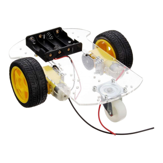
1 x buggy pack including instructions leaflet
(check parts in pack against leaflet) (a)
4 x wires (b)
1 x micro:bit edge connector (c)
1 x L9110s motor driver (d)
4 x jumper leads – green, yellow, blue,
burgundy (e)
2 x half-jumper leads – black, red (f)
1 x cable tie (g)
4 x AA batteries (h)
Other Requirements
BBC micro:bit
Mini-USB cable
Battery pack for micro:bit
Soldering iron & solder
Wire strippers
Small screwdriver
Sticky tape
(Optional) Electrical tape or duct tape
(Optional) Glue gun
Page 1 of 5
Advertisement
Table of Contents

Summary of Contents for Creative Computing Robot Buggy
- Page 1 Robot Buggy – Build Instructions Parts List 1 x buggy pack including instructions leaflet (check parts in pack against leaflet) (a) 4 x wires (b) 1 x micro:bit edge connector (c) 1 x L9110s motor driver (d) 4 x jumper leads – green, yellow, blue, burgundy (e) 2 x half-jumper leads –...
- Page 2 Robot Buggy – Build Instructions A. Preparation Step 1: Peel paper backing from robot chassis. Step 2: Take out the instructions from the buggy pack and scan through the pictures, so you know which part attaches where. B. Soldering Step 1: Solder the spare wires to the motors.
- Page 3 Robot Buggy – Build Instructions C. Testing Step 1: Plug the black lead onto the pin labelled GND on the motor driver. Step 2: Plug the red lead onto the pin labelled Vcc on the motor driver. Step 3: Put the AA batteries into the battery holder and flip the switch to the on position.
- Page 4 Robot Buggy – Build Instructions Step 5: Use the cable tie, through the middle square holes at the wider end of the chassis, to attach the edge connector to the chassis. Step 6: Plug the jumper leads into the edge connector in the following...
- Page 5 Robot Buggy – Build Instructions F. Final Test Step 1: Place your finished robot buggy on the floor with plenty of space around it. Step 2: Press the A button on your micro:bit and watch it go! TROUBLESHOOTING – Is your buggy not working as expected? Your buggy is not moving at all! Check that your micro:bit is showing a smiley face -- Go back to E.
Need help?
Do you have a question about the Robot Buggy and is the answer not in the manual?
Questions and answers