
Summary of Contents for CUES LAMP II
- Page 1 CUES LAMP II Lateral & Mainline Probe II OPERATION & MAINTENANCE MANUAL P/N LM903, Revision 18: 120220...
-
Page 2: Table Of Contents
Remote Reel Controller (Retrieve/Release) ....16 For Fiberglass Cable Assemblies ........20 When Using the Mini Pan & Tilt Compatible LAMPII Version ................22 LAMP II Push Wheel Replacement Guide ......24 Installing the Strain Relief Cables ........27 Flipping the Push Cable ............28 Operating the Reel Brake ............29 Line Tracing Cable Extension with LAMPII ......30... - Page 3 Equipment Maintenance ............59 CHAPTER 7 - Exploded View and Bill of Materials Exploded View and BOMs .............60 Miscellaneous Warranty Information ............108 CUES Material Return Policy ..........109 CUES Parts & Service ............111 Safety Precautions & Equipment ...........112 Record of Revisions ...............113 www.cuesinc.com, | salesinfo@cuesinc.com...
- Page 4 C/O Operator’s Manuals: ® Corporate Office 3600 Rio Vista Avenue Orlando, Florida 32805 More locations to serve you! CUES ® Corporate Office CUES ® Atlanta CUES West CUES ® Northern California 1943 S. Augusta Ct.
- Page 5 LAMPII CUES multi-conductor system (including steerable). throughout the manual, is available in several All existing CUES multi-conductor systems can be different configurations. retrofitted to operate the LAMPII. If the LAMPII is being installed on an existing...
-
Page 6: System Description
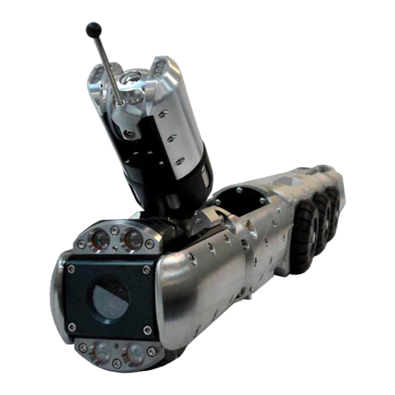
SYSTEM DESCRIPTION LAMPII shown with optional Lateral Pan & Tilt Camera The CUES LAMPII is designed to perform pan and camera can locate house laterals from inside the tilt inspections of the mainline sewer pipe while mainline sewer pipe, the inspection can be carried... -
Page 7: Chapter 3 - Equipment Overview
An optional sonde, built into the lateral mini-camera, is available to help accurately locate the camera in metallic and non-metallic pipes. The sonde can operate with any constant tone, 512Hz locator/receiver. www.cuesinc.com, | salesinfo@cuesinc.com CUES Inc., LAMPII User Manual | LM903... -
Page 8: Lateral Pan & Tilt Camera (Optional)
• LAMPII function controller (LM320) • Lateral power control unit (LM341, LM342, LM354, LM355, LM356) • Lateral reel controller • Remote retrieve/release reel controller - LM353 • Game pad or CUES hand-held controllers - wireless or tethered www.cuesinc.com, | salesinfo@cuesinc.com CUES Inc.,... -
Page 9: Controllers
• Integrated levelwind / auto-retrieve (levelwind available with the stainless steel cable option only) Lateral Reel for the LAMPII Lateral Reel for Fiberglass Lateral Push Cable - Spring Cable Configuration Push Cable Configuration www.cuesinc.com, | salesinfo@cuesinc.com CUES Inc., LAMPII User Manual | LM903... - Page 10 10” - 15” 8” Pipe - for 6” Pipe for 12” + Rubber Pipe * 6” steel and 10” - 15” rubber not shown 6” Lined Pipe 8” Pipe - Steel www.cuesinc.com, | salesinfo@cuesinc.com CUES Inc., LAMPII User Manual | LM903...
-
Page 11: Large Pipe Equipment
P/N LM935 (Kit, Adapter, K2 Wheels to LAMPII) is available when mounting the large 14” Pneumatic Wheels to the LAMPII. For existing units, contact CUES Customer Service prior to installation to determine if the clutch is adjusted properly. Once this is accomplished, existing units can be field-retrofitted. - Page 12 | salesinfo@cuesinc.com CUES Inc., LAMPII User Manual | LM903...
- Page 13 | salesinfo@cuesinc.com CUES Inc., LAMPII User Manual | LM903...
-
Page 14: Adapting The Lampii To Different Pipe Configurations
6. Hold the wheel and spacer against the LAMPII shaft and secure the appropriate screw using an Allen wrench. 7. Tighten to 15 ft. lbs. IMPORTANT! When changing wheels, always apply anti-sieze compound, P/N CS407 or P/N 940700 grease, to all screw threads! www.cuesinc.com, | salesinfo@cuesinc.com CUES Inc., LAMPII User Manual | LM903... - Page 15 12-pin gold cable. Connect the multi-conductor gold cable to the top of the LAMPII, ensuring that the quick-connector is secure. Note the orientation of the top- conductor position for proper connector alignment. www.cuesinc.com, | salesinfo@cuesinc.com CUES Inc., LAMPII User Manual | LM903...
-
Page 16: Installing The Push Cable
Lay out the push cable and install the camera and centering ball. Pivot the camera head UP and insert the push camera up through the bottom of the unit as shown. www.cuesinc.com, | salesinfo@cuesinc.com CUES Inc., LAMPII User Manual | LM903... - Page 17 • Recommended settings: Gold Cable retrieval speed should be set according to pipe conditions with cables visually monitored for synchronization to prevent potential damage to the equipment. www.cuesinc.com, | salesinfo@cuesinc.com CUES Inc., LAMPII User Manual | LM903...
-
Page 18: For Stainless Steel Cable Assemblies
Install the spacer in the chamber before installing the nut. Apply anti-sieze compound, P/N CS407 or P/N 940700 grease, and then tighten the metal chamber nut (do not cross-thread). c. Connect the strain relief cables. www.cuesinc.com, | salesinfo@cuesinc.com CUES Inc., LAMPII User Manual | LM903... -
Page 19: Remote Reel Controller (Retrieve/Release)
REEL TOGGLE SWITCH: PRESS TO RELEASE OR RETRIEVE THE CABLE ON THE REEL. CONTROL TOGGLE SWITCH: PRESS TO SELECT LOCAL (HAND-HELD CONTROLLER) OR REMOTE CONTROLLER (LATERAL PCU). P/N LM353, CONTROLLER, REMOTE, RETRIEVE/RELEASE, LAMPII REEL www.cuesinc.com, | salesinfo@cuesinc.com CUES Inc., LAMPII User Manual | LM903... - Page 20 SYSTEM SET-UP & INSTALLATION Ensure that the grey/yellow cable is plugged into the rear of the Lateral PCU as shown below. REMOTE REEL CONTROLLER IN THE CONTROL ROOM www.cuesinc.com, | salesinfo@cuesinc.com CUES Inc., LAMPII User Manual | LM903...
- Page 21 When the operator is in LOCAL CONTROL when using the hand-held controller, the lateral reel switch on the Lateral PCU will become disabled. SPEED KNOB FORCE KNOB LATERAL REEL CONTROLLER AT REAR OF TRUCK www.cuesinc.com, | salesinfo@cuesinc.com CUES Inc., LAMPII User Manual | LM903...
- Page 22 NOTE: The (4) screws and locations (in below) are the same for each configuration. The other screw is located on the side of the unit. The other screw is located on the side of the unit. www.cuesinc.com, | salesinfo@cuesinc.com CUES Inc., LAMPII User Manual | LM903...
- Page 23 Attach the Spring End to the Push Cable: NOTE: Prior to mating the cable, ensure that both internal and external threads are clean of any debris, and then lubricate with anti-seize, CUES P/N #940700. Align the visual markers and guide pins and mate the connector ends together.
- Page 24 If using the Mini Pan & Tilt Camera, install the push cable into the LAMPII prior to installing the camera (not shown). www.cuesinc.com, | salesinfo@cuesinc.com CUES Inc., LAMPII User Manual | LM903...
- Page 25 24 in-lbs. Let the thread locker set for 30 minutes before operating. NOTE: The push wheel screws should be checked prior to each use to ensure proper tension. Place blue thread locker on the screws and secure the cover plate. www.cuesinc.com, | salesinfo@cuesinc.com CUES Inc., LAMPII User Manual | LM903...
- Page 26 SYSTEM SET-UP & INSTALLATION WHEN USING THE MINI P&T CAMERA COMPATIBLE LAMPII VERSION: If using the CUES Mini Pan & Tilt Camera with the LAMPII, perform the steps listed in the previous procedure as well as the following: To uninstall and/or reinstall the push cable when using the Mini Pan & Tilt Camera compatible LAMPII version, it’s necessary to remove and/or install the underbody push cable guide, P/N LM730, as follows:...
- Page 27 • LM920 BOM and exploded view drawings are included in Chapter 7. www.cuesinc.com, | salesinfo@cuesinc.com CUES Inc., LAMPII User Manual | LM903...
-
Page 28: Lamp Ii Push Wheel Replacement Guide
Note: Top and bottom orientations are for the push block, which sits upside-down in the LAMP II. Replace the bottom wheels on the corners as indicated. Refer to the image on the opposite page. - Page 29 | salesinfo@cuesinc.com CUES Inc., LAMPII User Manual | LM903...
- Page 30 Attach the Lateral Video Cable to the Push Cable: NOTE: Prior to mating the cable, ensure that both internal and external threads are clean of any debris, and then lubricate with anti-seize, CUES P/N #940700. Align the visual markers and guide pins and mate the cable ends together.
-
Page 31: Installing The Strain Relief Cables
(This equates to the strain relief being approximately 2 inches from the end of the cord grip spring). Tighten the screws on the strain relief clamps. Ensure the wire rope strain relief cables are taught and the video cables have some slack. www.cuesinc.com, | salesinfo@cuesinc.com CUES Inc., LAMPII User Manual | LM903... - Page 32 Refer to the INSTALLING THE LAMPII IMMOBILIZING BLOCK procedure in this chapter for pictures to differenciate between the old versus new bump stops. Bump Stops, P/N LM718 www.cuesinc.com, | salesinfo@cuesinc.com CUES Inc., LAMPII User Manual | LM903...
- Page 33 Use the lever to activate the brake and stop the movement of the reel. To lock the reel, push the lever through it’s full motion. In this position, cable payout and retrieval is locked. www.cuesinc.com, | salesinfo@cuesinc.com CUES Inc., LAMPII User Manual | LM903...
-
Page 34: Line Tracing Cable Extension With Lampii
IMPORTANT: The LM600 should ONLY be used during line tracing. It will act as a massive antenna on the ground line and could induce video noise. It should be detached when not in use. Refer to the Transmitter Manual for detailed operation instructions. www.cuesinc.com, | salesinfo@cuesinc.com CUES Inc., LAMPII User Manual | LM903... - Page 35 | salesinfo@cuesinc.com CUES Inc., LAMPII User Manual | LM903...
- Page 36 Attach the interconnect cable to the 12-pin connector as shown. Ensure that pin 1 is aligned on the swivel connector and the rear view camera 12-pin connector. www.cuesinc.com, | salesinfo@cuesinc.com CUES Inc., LAMPII User Manual | LM903...
- Page 37 • For existing units: If the rear housing does not have the two holes shown in the image in step 4 above, it must be sent to CUES for modification prior to rear view camera installation. • Rear-view camera operation requires a K2/Summit control system or a panel-mounted rear-view camera toggle switch for non-K2/Summit systems.
- Page 38 Adjust the cable clamp to ensure there is slack in both the retrieval and in-line positions. For further instructions, refer to P/N LM388-INST. NOTE: the rear view camera lights will remain ON at all times. www.cuesinc.com, | salesinfo@cuesinc.com CUES Inc., LAMPII User Manual | LM903...
- Page 39 MAINLINE and LATERAL cameras only. • For a K2 system with a CUES hand-held controller: Pressing the “MAIN CAMERA” button will always switch the view to the MAINLINE camera, and pressing the “REAR CAMERA” button will always switch the view to the LATERAL camera. However, if a rear-viewing camera has been selected on the K2 Equipment Configuration Screen, pressing the “REAR...
- Page 40 2016, use P/N LM758. For older assemblies, use P/N LM275. Note: The two versions can be visually differentiated by the ridges present for the replaceable bump stops. Refer to the figures on the opposite page. continued... www.cuesinc.com, | salesinfo@cuesinc.com CUES Inc., LAMPII User Manual | LM903...
- Page 41 P/N LM357 With Bump Stop Ridges Camera Head Assembly with Launcher, P/N LM325: No Bump Stop Ridges www.cuesinc.com, | salesinfo@cuesinc.com CUES Inc., LAMPII User Manual | LM903...
- Page 42 Ensure that the curves of the top are facing the sides and front of the LAMPII. 3. Insert the screw and fasten tight. From L to R, Bottom, Screw, Top www.cuesinc.com, | salesinfo@cuesinc.com CUES Inc., LAMPII User Manual | LM903...
- Page 43 Figure 1: Insert the Bottom Piece as shown. Figure 2: Position the cover. Figure 3: Fasten the screw. www.cuesinc.com, | salesinfo@cuesinc.com CUES Inc., LAMPII User Manual | LM903...
-
Page 44: Immobilizing The Camera Head When Using The Mini Pan & Tilt Camera Compatible Lampii Version
Using the screw that was removed in Step #1, install it on the bottom of the camera guide with an Allen Wrench as shown. Mini Pan & Tilt Camera Guide, P/N LM729 Remove screw from here Then install screw here www.cuesinc.com, | salesinfo@cuesinc.com CUES Inc., LAMPII User Manual | LM903... - Page 45 FYI: The immobilizing block screw size is engraved on the block for future reference. www.cuesinc.com, | salesinfo@cuesinc.com CUES Inc., LAMPII User Manual | LM903...
- Page 46 Ensure that LAMPII is selected for the PCU SWITCH transporter field (refer to the next page). K2 SWITCH Ensure that all controls are functioning properly prior to placing the LAMPII in the pipe! www.cuesinc.com, | salesinfo@cuesinc.com CUES Inc., LAMPII User Manual | LM903...
- Page 47 Master, Mud Master, Koala, Compact Pipe Ranger, Ultra-Shorty-21, Ultra-Shorty-III, WTR, LAMPII Default - None Status Line - ARROW UP/DOWN to view transporter list. MULTI CONDUCTOR EQUIPMENT CONFIGURATION SCREEN ===CUES K2 EQUIPMENT CONFIGURATION === REV: R011 CONFIGURATION CORRECT? NO REEL: K2 Portable CONFIG. REELS? NO CABLE: WM305(Platinum) LENGTH: 10 FT.
- Page 48 PRESS TO TOGGLE BETWEEN THE FRONT- CONTROL VOLTAGES VIEW, LATERAL, AND REAR-VIEW CAMERAS LAMP II IN LATERAL MODE WITH MPT CAMERA: PRESSING THE LIFT BUTTON WILL CAUSE THE CAMERA TO PERFORM AN AUTOMATED JOINT INSPECTION. LAMP II IN LATERAL MODE...
- Page 49 PRESS THE REEL AND “OFF” BUTTONS SIMULTANEOUSLY FOR RETRIEVE MODE GREEN Works when using a Mini Pan & LAMP II IN LATERAL MODE: PRESS THE REEL BUTTON TO RETRACT THE LATERAL Tilt Camera when in lateral mode. CAMERA (NOTE: REEL FUNCTIONS DISABLED). SPEED ALTERNATES BETWEEN FAST AND SLOW WITH EACH PRESS.
- Page 50 CUES LOGITECH GAME PAD FUNCTIONS FUNCTIONAL CHECKOUT WHEN USING A CUES TRANSPORTER AND/OR LAMP II & MICRO PAN & TILT CAMERA MICRO PAN & TILT: WHEN COMBINED WITH THE DPAD ‘+’ OR ‘-‘ INCREASE/ DECREASE THE FLOOD LIGHTS. COLOR CODES...
- Page 51 Works when using a Micro Pan & Tilt Camera when in lateral mode. LAMP II IN LATERAL MODE: PRESS THE REEL BUTTON TO RETRACT THE LATERAL CAMERA (NOTE: REEL FUNCTIONS DISABLED). SPEED ALTERNATES BETWEEN FAST AND SLOW WITH EACH PRESS.
- Page 52 HAND-HELD K2 CONTROLLER FUNCTIONS FUNCTIONAL CHECKOUT (FOR SYSTEMS USING A K2 SUMMIT SYSTEM) www.cuesinc.com, | salesinfo@cuesinc.com CUES Inc., LAMPII User Manual | LM903...
- Page 53 CUES www.cuesinc.com, | salesinfo@cuesinc.com CUES Inc., LAMPII User Manual | LM903...
- Page 54 Turn ON the lateral PCU (P/N LM340). The LED should be green, indicating that a non- steerable transporter has been detected. Turn ON the multi-conductor PCU (P/N PC600). Set the light voltage to 150-160 volts. www.cuesinc.com, | salesinfo@cuesinc.com CUES Inc., LAMPII User Manual | LM903...
- Page 55 Turn ON the double-data, P/N TS801. Turn ON the recording device and monitors. After the LED on the LAMPII functions controller lights up and the camera is initialized, refer to Chapter 5, Functional Checkout. www.cuesinc.com, | salesinfo@cuesinc.com CUES Inc., LAMPII User Manual | LM903...
- Page 56 Ensure that the video is displayed on the monitor; clean the lens if necessary • Check / verify the footage accuracy Ensure that all controls are functioning properly prior to placing the LAMPII in the pipe! www.cuesinc.com, | salesinfo@cuesinc.com CUES Inc., LAMPII User Manual | LM903...
-
Page 57: Chapter 6 - Operating The Lampii
If the lights are not on or the internal camera light overvoltage protection circuit is enabled, the sonde will not function. www.cuesinc.com, | salesinfo@cuesinc.com CUES Inc., LAMPII User Manual | LM903... -
Page 58: Operating The Lampii
Turn OFF the lateral reel, transporter, and launcher controllers. 10. If this is the last inspection of the day, refer to the Equipment Maintenance procedure in this chapter for clean up instructions. www.cuesinc.com, | salesinfo@cuesinc.com CUES Inc., LAMPII User Manual | LM903... -
Page 59: Centering The Lampii In The Pipe
5. To use the power reverse, make sure the directional switch on the transporter controller or K2 game pad controller (depending on your specific system) is set to REVERSE and then slowly advance the speed control. www.cuesinc.com, | salesinfo@cuesinc.com CUES Inc., LAMPII User Manual | LM903... -
Page 60: Operating The Picture In Picture (Pip)
NOTE: All BNC video connections at the rear of the Telpix PiP unit have been completed during assembly at CUES. Do not disconnect or move any of the BNC connectors as the unit will not perform correctly. Make all connections to the RCA connectors located at the rear of the right side mounting bracket (located at the left side in the rear view below). - Page 61 NOTE: The telpix unit was designed to accept up to four separate video sources. Only two inputs are used with cues equipment. The unit has an internal “alarm” mode which cannot be disabled. If any of the video input signals are interrupted, the unit will display the four quadrant screen briefly (the “alarm”...
-
Page 62: Retrieving The Lampii
After retrieving the LAMPII from the manhole, remove the push cable from the launcher and disconnect it from the lateral video cable. Coil the push cable starting at the camera end. www.cuesinc.com, | salesinfo@cuesinc.com CUES Inc., LAMPII User Manual | LM903... -
Page 63: Equipment Maintenance
The plate is attached with four screws: P/N 103045 in LM350-2, -4, & -9 configurations, and P/N HW2818 in LM350-6,-7,-8, & -10 configurations(a cover is also present in these configurations). www.cuesinc.com, | salesinfo@cuesinc.com CUES Inc., LAMPII User Manual | LM903... - Page 64 LAMPII BOM & EXPLODED VIEW DRAWINGS FIGURE 1A. LAMP II,80’PUSH CABLE & SELF UPRIGHT/NTSC, LM350 www.cuesinc.com, | salesinfo@cuesinc.com CUES Inc., LAMPII User Manual | LM903...
- Page 65 FIGURE 1B. LAMP II,80’PUSH CABLE & SELF UPRIGHT/NTSC, LM350 www.cuesinc.com, | salesinfo@cuesinc.com CUES Inc., LAMPII User Manual | LM903...
- Page 66 LAMPII BOM & EXPLODED VIEW DRAWINGS LAMP II FIGURE 1C. LAMP II,80’PUSH CABLE & SELF UPRIGHT/NTSC, LM350 www.cuesinc.com, | salesinfo@cuesinc.com CUES Inc., LAMPII User Manual | LM903...
- Page 67 LAMP II FIGURE 1D. LAMP II,80’PUSH CABLE & SELF UPRIGHT/NTSC, LM350 www.cuesinc.com, | salesinfo@cuesinc.com CUES Inc., LAMPII User Manual | LM903...
- Page 68 LAMPII BOM & EXPLODED VIEW DRAWINGS LAMP II FIGURE 1E. LAMP II,80’PUSH CABLE & SELF UPRIGHT/NTSC, LM350 www.cuesinc.com, | salesinfo@cuesinc.com CUES Inc., LAMPII User Manual | LM903...
- Page 69 LAMP II FIGURE 1F. LAMP II,80’PUSH CABLE & SELF UPRIGHT/NTSC, LM350 www.cuesinc.com, | salesinfo@cuesinc.com CUES Inc., LAMPII User Manual | LM903...
- Page 70 LAMPII BOM & EXPLODED VIEW DRAWINGS LAMP II FIGURE 1G. LAMP II,80’PUSH CABLE & SELF UPRIGHT/NTSC, LM350 www.cuesinc.com, | salesinfo@cuesinc.com CUES Inc., LAMPII User Manual | LM903...
- Page 71 LAMP II FIGURE 1H. LAMP II,80’PUSH CABLE & SELF UPRIGHT/NTSC, LM350 www.cuesinc.com, | salesinfo@cuesinc.com CUES Inc., LAMPII User Manual | LM903...
- Page 72 LAMPII BOM & EXPLODED VIEW DRAWINGS FIGURE 1I. LAMP II,80’PUSH CABLE & SELF UPRIGHT/NTSC, LM350 www.cuesinc.com, | salesinfo@cuesinc.com CUES Inc., LAMPII User Manual | LM903...
- Page 73 FIGURE 1J. LAMP II,80’PUSH CABLE & SELF UPRIGHT/NTSC, LM350 www.cuesinc.com, | salesinfo@cuesinc.com CUES Inc., LAMPII User Manual | LM903...
- Page 74 LAMPII BOM & EXPLODED VIEW DRAWINGS >SPRING PUSH CABLE OPTION LAMP II,80’PSH CBL&SLF UPR/SND/NTSC (See Figure 1), Rev. X, LM350 ITEM # DESCRIPTION 0001 HOUSING,ROTATE MOTOR LM011 0002 GEAR,SPUR,30TEETH,SPLINED,LAMPII LM024 0003 PLATE,PUSH CABLE GUIDE,UPPER LM027 0004 DRIVESHAFT,PUSH DRIVE,LAMP II LM031...
- Page 75 LAMP II,80’PSH CBL&SLF UPR/SND/NTSC (See Figure 1), Rev. X, LM350 ITEM # DESCRIPTION 0040 SCREW,CAP,SKT HD,10-32X1-3/4LG,SST HW118 0041 SCREW,CAP,SOC HEAD,10-32X5/8,SST HW134 0042 SCREW,PAN,4-40X1/4 MACHINE HW227 0043 BEARING,THRUST,BRONZ,.502X.753X1/16 HW321 0044 SCREW,CAP HD,10-32X2-3/4LG,SST HW362 0045 BEARING,BALL,9X17X5,SEALED HW457 0046 O-RING,2-168,BUNA HW617 0047 SCREW,BUTTON HD 6-32X5/16 SST SKT...
- Page 76 LAMPII BOM & EXPLODED VIEW DRAWINGS >SPRING PUSH CABLE OPTION LAMP II,80’PSH CBL&SLF UPR/SND/NTSC (See Figure 1), Rev. X, LM350 ITEM # DESCRIPTION 0079 MRO-ANTI-SEIZE,LPS NICKEL,P/N 03908 CS407 0080 LABEL,THERMAL XFR,1.500”W X .500”H CS221 0081 LABEL,LASERTAB MARKER, .560 X .560...
- Page 77 LAMP II,ALT PSH DR,NO CAM&PSH CBL, Rev. X, LM350-2 ITEM # DESCRIPTION 0001 HOUSING,ROTATE MOTOR LM011 0002 GEAR,SPUR,30TEETH,SPLINED,LAMPII LM024 0004 DRIVESHAFT,PUSH DRIVE,LAMP II LM031 0005 SHAFT,WORM DRIVE,LAMPII LM039 0008 CONNECTOR,QUICK,12PIN,LAMP II/CPR LM074 0009 AXLE,FRONT & INTERMEDIATE,LAMPII LM075 0010 HALL SENSOR MAGNET ASSY,SHORT...
- Page 78 LAMPII BOM & EXPLODED VIEW DRAWINGS LAMP II,ALT PSH DR,NO CAM&PSH CBL, Rev. X, LM350-2 ITEM # DESCRIPTION 0054 BEARING,NEEDLE,15MM X 21MM X12MM HW1757 0055 O-RING,2-045,BUNA-N,SHORE A70 HW1828 0056 BEARING,THRUST,1.00 OD X .50 ID HW1832 0057 SCREW,FLAT,8-32X.313,PHIL,SS HW1846 0058 RING,RTG,EXT,SNP,1/2DIA SS,...
- Page 79 LAMP II,ALT PSH DR,NO CAM&PSH CBL, Rev. X, LM350-2 ITEM # DESCRIPTION 0097 RING,RETAIN.,SPIRAL,.500ID,.035 THK HW605 0098 TOOL,NUT DRIVER,1/4IN CS501 0099 MRO-CLEANER,CONTACT,DEOXIT GLD,25ML CS498 0200 HOUSING,2-PIN,2MM 712864 0201 WIRE,#24 BLACK TEFLON 713335 0202 WIRE,#24 RED TEFLON 713337 0203 CONTACT 715087 0204 TUBE,SHRINK,1/16”...
- Page 80 LAMPII BOM & EXPLODED VIEW DRAWINGS FIGURE 2A. SPRING ASSY, LATERAL CAMERA,LAMPII, LM335 www.cuesinc.com, | salesinfo@cuesinc.com CUES Inc., LAMPII User Manual | LM903...
- Page 81 FIGURE 2B. SPRING ASSY, LATERAL CAMERA,LAMPII, LM335 www.cuesinc.com, | salesinfo@cuesinc.com CUES Inc., LAMPII User Manual | LM903...
- Page 82 LAMPII BOM & EXPLODED VIEW DRAWINGS FIGURE 2C. SPRING ASSY, LATERAL CAMERA,LAMPII, LM335 www.cuesinc.com, | salesinfo@cuesinc.com CUES Inc., LAMPII User Manual | LM903...
- Page 83 TUBE,SHRINK,BLACK 1/4”SCL 712587 0023 TUBE,SHRINK,1/16” 712593 0024 WIRE,#30 BLACK TEFLON 713205 0025 WIRE,#30 GREEN TEFLON 713210 0026 WIRE,#30 RED TEFLON 713207 0027 WIRE,#30 WHITE TEFLON 713213 0028 MRO-LUBRICANT,RUBBER EMULSION 439786 www.cuesinc.com, | salesinfo@cuesinc.com CUES Inc., LAMPII User Manual | LM903...
- Page 84 LAMPII BOM & EXPLODED VIEW DRAWINGS FIGURE 3A. LED LIGHTHEAD ASSY,OZ III, MZ302 www.cuesinc.com, | salesinfo@cuesinc.com CUES Inc., LAMPII User Manual | LM903...
- Page 85 FIGURE 3B. LED LIGHTHEAD ASSY,OZ III, MZ302 www.cuesinc.com, | salesinfo@cuesinc.com CUES Inc., LAMPII User Manual | LM903...
- Page 86 WIRE,#24 RED TEFLON 713337 0024 WIRE,#24 BLACK TEFLON 713335 0025 CONTACT 715087 0026 TUBE,SHRINK,BLACK 3/32” 712595 0027 MRO-REMOVABLE LCK,ND 121200-50,BLUE 440061 0028 SCREW,SET,6-32X3/16 SST 100991 0029 MRO-LUBRICANT,O-RING 2 OZ TUBE 439986 www.cuesinc.com, | salesinfo@cuesinc.com CUES Inc., LAMPII User Manual | LM903...
- Page 87 FIGURE 4A. COVER ASSY,ELECTRONICS BAY, LAMP II, LM304 www.cuesinc.com, | salesinfo@cuesinc.com CUES Inc., LAMPII User Manual | LM903...
- Page 88 LAMPII BOM & EXPLODED VIEW DRAWINGS LAMP II FIGURE 23B. COVER ASSY,ELECTRONICS BAY, LAMP II, LM304 www.cuesinc.com, | salesinfo@cuesinc.com CUES Inc., LAMPII User Manual | LM903...
- Page 89 FIGURE 23C. COVER ASSY,ELECTRONICS BAY, LAMP II, LM304 www.cuesinc.com, | salesinfo@cuesinc.com CUES Inc., LAMPII User Manual | LM903...
- Page 90 LAMPII BOM & EXPLODED VIEW DRAWINGS COVER ASSY,ELECTRONICS BAY, LAMP II, (See Figure 4), LM304, Rev. E ITEM # DESCRIPTION 0001 COVER,ELECTRONIC BAY,THK WALL,LMPII LM750 0002 CLEVIS,HARNESS CONN, MODIFIED (L) LM751 0003 CLEVIS,HARNESS CONN, MODIFIED (R) LM751-1 0004 CABLE ASSY,RETRIEVAL,LAMPII...
- Page 91 FIGURE 5A. CABLE ASSY,PUSH,80FT,LMP,0.24 ARMOR, LAMP II, LT603 www.cuesinc.com, | salesinfo@cuesinc.com CUES Inc., LAMPII User Manual | LM903...
- Page 92 LAMPII BOM & EXPLODED VIEW DRAWINGS FIGURE 5B. CABLE ASSY,PUSH,80FT,LMP,0.24 ARMOR, LAMP II, LT603 www.cuesinc.com, | salesinfo@cuesinc.com CUES Inc., LAMPII User Manual | LM903...
- Page 93 CABLE ASSY,PUSH,80FT,LMP,0.24 ARMOR, LAMP II, (See Figure 5), LT603, Rev. J ITEM # DESCRIPTION 0002 END,PROFILED,SPRING CABLE,LAMP LT090 0003 TOW CABLE,12”,PUSHCABLE,LAMP LT150 0004 SPRING,CABLE,PUSH,80’,LAMP LT151 0006 STRAIN RELIEF,CLAMSHELL,PUSHCA,LAMP LT152 0017 CABLE ASSY,INNER ARMORED,87FT LT623 0022 KIT,REPAIR,PSHCBL,4PIN END,LMP,0.24 RP120 0033 MRO-REMOVABLE LCK,ND 121200-50,BLUE...
- Page 94 LAMPII BOM & EXPLODED VIEW DRAWINGS FIGURE 6. CABLE ASSY,CAMERA,LATERAL 1,000’, LT318 www.cuesinc.com, | salesinfo@cuesinc.com CUES Inc., LAMPII User Manual | LM903...
- Page 95 FIGURE 7. CABLE ASSY, PUSH, BLUE, HYT, 80’, LAMP II, LM712 www.cuesinc.com, | salesinfo@cuesinc.com CUES Inc., LAMPII User Manual | LM903...
- Page 96 LAMPII BOM & EXPLODED VIEW DRAWINGS CABLE ASSY,PUSH,BLUE, HYT, 80’,LAMPII, (See Figure 7), LM712-H, Rev. G ITEM # DESCRIPTION 0001 FITTING,CRIMP,PUSH CABLE,LAMPII LM708 0003 CABLE,PUSH,BLUE,HYT,80’,LAMP II LM709-1H 0004 PCB ASSY,RECEPT,ALT PSH CBL,LAMPII LM409 0005 CONN,HOUSING,DUAL,10P,1MM HIROSE EC1843 0006 WIRES,CRIMMPED,PUSH CABLE,P&T...
- Page 97 FIGURE 8. CABLE ASSY,LAT,BRN,6CND,1000’, LAMP II, LM336 www.cuesinc.com, | salesinfo@cuesinc.com CUES Inc., LAMPII User Manual | LM903...
- Page 98 0016 TUBE,SHRINK,BLACK 1/8” 712789 0017 TUBE,SHRINK,BLACK 1/4”RNF 712576 0018 MYLAR,INSULATNG,.75”X3”,SPLCE CHBR LM293 0019 TUBE,SHRINK,BLACK 3/4”ADH 712579 0020 TUBE,SHRINK,BLACK 4:1 RATIO 715010 0021 TAPE,SPLICING,RUBBER,SLF VULCANZG CS058 0022 MRO-TAPE,TEFLON,½” X 520” CS171 www.cuesinc.com, | salesinfo@cuesinc.com CUES Inc., LAMPII User Manual | LM903...
- Page 99 LAMP II FIGURE 9. INSTRUCTION SHEET, CABLE ASSY, LAT, 1000’, LAMP II, LM925-INST www.cuesinc.com, | salesinfo@cuesinc.com CUES Inc., LAMPII User Manual | LM903...
- Page 100 LAMPII BOM & EXPLODED VIEW DRAWINGS LAMP II FIGURE 10A. PUSH DRIVE ASSY, ALTERNATE,LAMP II, LM331 www.cuesinc.com, | salesinfo@cuesinc.com CUES Inc., LAMPII User Manual | LM903...
- Page 101 LAMP II FIGURE 10B. PUSH DRIVE ASSY, ALTERNATE,LAMP II, LM331 www.cuesinc.com, | salesinfo@cuesinc.com CUES Inc., LAMPII User Manual | LM903...
- Page 102 LAMPII BOM & EXPLODED VIEW DRAWINGS LAMP II FIGURE 10C. PUSH DRIVE ASSY, ALTERNATE,LAMP II, LM331 www.cuesinc.com, | salesinfo@cuesinc.com CUES Inc., LAMPII User Manual | LM903...
- Page 103 LAMP II FIGURE 10D. PUSH DRIVE ASSY, ALTERNATE,LAMP II, LM331 www.cuesinc.com, | salesinfo@cuesinc.com CUES Inc., LAMPII User Manual | LM903...
- Page 104 LAMPII BOM & EXPLODED VIEW DRAWINGS PUSH DRIVE ASSY,ALTERNATE,LAMP II, (See Figure 10), LM331, Rev. E ITEM # DESCRIPTION 0001 COVER PLATE,FRONT,PUSH DRIVE LM205 0002 COVER PLATE,BOTTOM,PUSH DRIVE LM206 0003 GEAR,SPUR,32DP,34T,20PA,LONG SHAFT LM208 0004 GEAR,PILT,SPUR,32DP,24T,20PA,PSH DR LM210 0005 SHAFT,GEAR,QUAD,24DP,LH,PUSH DRIVE...
- Page 105 LAMP II FIGURE 11. KIT,LRG PUSH WHEELS,,ALT,LAMP II, LM920 www.cuesinc.com, | salesinfo@cuesinc.com CUES Inc., LAMPII User Manual | LM903...
- Page 106 LAMPII BOM & EXPLODED VIEW DRAWINGS KIT,LRG PUSH WHEELS,,ALT,LAMP II, (See Figure 11), LM920, Rev. B ITEM # DESCRIPTION 0001 ROLLER,BOTTOM,PUSH DRIVE,LARGE LM223-1 0002 ROLLER,TOP,PUSH DRIVE,LARGE LM226-1 0003 SCREW,CAPTIVE,HEX,8-32X.500,SS LM227 0004 WASHER,CAPTIVE,.423OD,8-32,SS LM228 0005 RING,RETAINING,CRESANT,EXT,5/16,SST HW2118 0006 WASHER,FLAT,#8,UHMW HW2122 0007 RING,RETAINING,SPIRAL,INT 7/16”,SST...
- Page 107 FIGURE 12. KIT,X-LRG PUSH WHEELS,,ALT,LAMP II, LM926 www.cuesinc.com, | salesinfo@cuesinc.com CUES Inc., LAMPII User Manual | LM903...
- Page 108 LAMPII BOM & EXPLODED VIEW DRAWINGS KIT,X-LRG PUSH WHEELS,,ALT,LAMP II, (See Figure 12), LM926, Rev. - ITEM # DESCRIPTION 0001 ROLLER,BOTTOM,PSH DRV,XTRA LRG LM223-2 0002 ROLLER,TOP,PSH DRV,XTRA LRG LM226-2 0003 SCREW,CAPTIVE,HEX,8-32X.500,SS LM227 0004 WASHER,CAPTIVE,.423OD,8-32,SS LM228 0005 RING,RETAINING,CRESANT,EXT,5/16,SST HW2118 0006 WASHER,FLAT,#8,UHMW...
- Page 109 LM363 0002 TUBE,POLYCARB,MOD CHUTE,18”L LM297-1 0003 TUBE,POLYCARB,MOD CHUTE,14”L LM297-2 0004 TUBE,POLYCARB,MOD CHUTE,10”L LM297-3 0005 KIT,ADAPTER,14” PNEU WHEELS,LAMP II LM935 0006 INST SHEET,MOD,WHL/ANG CHUTE,24-36” LM931-INST LM932, KIT, MODULAR, STRAIGHT CHUTE, 24” - 36” 0001 CHUTE ASSY,STRAIGHT,LRG PIPE LM362 0002 TUBE,POLYCARB,MOD CHUTE,18”L...
- Page 110 LAMPII BOM & EXPLODED VIEW DRAWINGS LARGE PIPE EQUIPMENT LM363, ANGLED CHUTE www.cuesinc.com, | salesinfo@cuesinc.com CUES Inc., LAMPII User Manual | LM903...
- Page 111 LM935, K2 WHEELS TO LAMP II ADAPTER KIT KIT,ADAPTER,14” PNEU WHEELS,LAMP II, LM935 0001 WHEEL ASSY,PNEUMATIC,14” MD046 0002 SPACER,ADPTR,2.63”,K2 WHEELS-LMII LM294-2 0003 PLATE,RTNG,K2 WHEELS,FRNT-LMII LM295-1 0004 WASHER,FLAT,5/16 SST 101741 0005 SCREW,HEX,5/16-24,MODOD HW2475 0006 SCREW,HEX,M6X75MM,ZN PL HW2407 0007 WASHER,FLAT,M6XØ12X1.5MM SST HW1738...
- Page 112 (12) months from the date of shipment of materials by CUES to the purchaser. CUES’ obligation under this warranty is limited, at CUES’ option, to replacing or repairing, free of charge, any defective materials returned, freight prepaid, to the CUES designated service facility.
- Page 113 CUES Customer Service at 1-800-327-7791. PERSONAL SAFETY EQUIPMENT & TRAINING CUES stresses the use of appropriate safety equipment while working in and around manholes and during system operation. Safety should constantly remain the utmost priority. NOTE: The user of CUES products is responsible for all training and operation under federal, state and local guidelines and regulations for both confined space entry and traffic control.
-
Page 114: Cues Material Return Policy
CUES, at its’ option, may credit freight charges both ways. 10. The parts must be returned to CUES within 5 days of receipt of the MRA for credit to be granted. Under normal circumstances, a warranty determination can be made within 30 days, and if under warranty, the part will be replaced at no charge. - Page 115 PARTS WILL BE RETURNED TO CUSTOMER AT CUSTOMER EXPENSE WITHOUT AN MRA NUMBER DOCUMENTED ON BOX. CUES IS NOT RESPONSIBLE FOR SHIPMENT FROM CUSTOMER TO CUES. Use this section as a Packing Slip.
-
Page 116: Cues Parts & Service
24 hours after receipt of the order. Whether you need a camera or a fuse, CUES will quickly process and ship your order in accordance with your schedule requirements! Our experienced parts professionals can help you with parts identification, shipping... -
Page 117: Record Of Revisions
As engineering changes to this hardware are made at CUES, necessary information in the manual will be revised to reflect those changes. The latest change level and the rationale for any change(s) will be explained in tabular format on this page to allow the manual user to be better equipped should the need arise to call CUES regarding technical information. - Page 118 Pipe profiling is accomplished via Laser for Sonar based systems. CUES has the most locations and dealers available to serve you! To find a local CUES facility, find the operating hours for a particular location, or to contact us at your most convenient stocking location, please log onto our website at www.cuesinc.com...
Need help?
Do you have a question about the LAMP II and is the answer not in the manual?
Questions and answers