Table of Contents
Advertisement
Advertisement
Table of Contents

Summary of Contents for NeuWave Medical Certus 140
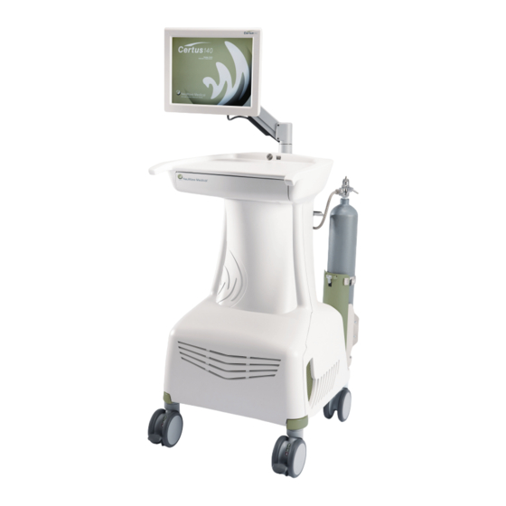
- Page 1 2.45 GHz Ablation System User Reference Manual Software Version 3.0.X...
- Page 2 Serial Numbers are formatted in the following manner: SN: NMYYZDDXXXXX Where: NM is a two-digit code identifying NeuWave Medical as the manufacturer and YY is the last two digits of the year of manufacture. Z is a one character code identifying the unit as new (N) or remanufactured (R).
-
Page 3: Table Of Contents
Certus 140™ Table of Contents Chapter 1 Introduction ......................1-1 What is a Certus 140™ Ablation System? ............... 1-1 Indications For Use Statement ................1-2 Using this manual ....................1-2 Symbols used in manual or on equipment ............... 1-3 Chapter 2 Warnings and Cautions ..................2-1 Chapter 3 System Overview and Setup ................3-1... - Page 4 NeuWave Medical ® Chapter 5 After a Procedure ....................5-1 End Procedure ......................5-1 Turning the System Off .................... 5-1 Probe Disposal ....................... 5-1 AC Power Cord....................... 5-1 Positioning System Display for Transport/Storage ........... 5-1 Disconnecting CO Cylinders .................. 5-2 PDM Disconnection and Storage ................5-4 Footswitch ......................
-
Page 5: Chapter 1 Introduction
In open surgical applications, the PDM can mount directly to the Certus 140 or to the surgical table. The PDM also uses a larger, more efficient cable from the PDM to the power amplifier. This increased efficiency of the larger cable enables more energy to be sent to the energy delivery accessory. -
Page 6: Indications For Use Statement
This feature helps prevent the probe from moving once it has been placed in the desired location. The Certus 140 Ablation System can be used in either Ablation Mode or Surgical Mode. These two modes deliver power the same way, but the user interface and workflow in the two modes are different and optimized for different applications. -
Page 7: Using This Manual
This manual uses text formatting to identify different aspects of the product and its use. NOTE: This user manual covers the use of the Certus 140 with both ablation probes and surgical tools. To reduce potential confusion, the term “Probe” is used throughout the manual to refer to both ablation probes and surgical tools. -
Page 8: Symbols Used In Manual Or On Equipment
® Symbols used in manual or on equipment Symbols replace words on the equipment, on the display, or in NeuWave Medical manuals and Instructions for Use. The following symbols appear on the Certus 140 system and accessories. Caution: Federal law in the US... -
Page 9: Chapter 2 Warnings And Cautions
Certus 140™ Warnings and Cautions Users should be familiar with all warnings and cautions prior to using the Certus 140 Ablation System. The warnings and cautions listed in this chapter also appear in the relevant sections of the manual. WARNINGS • NeuWave recommends against the use of the Certus 140 2.45 GHz Ablation System in the following situations: - Pregnant patients –... - Page 10 • Inspect the system before each use. If there is evidence of damage, do not use the system. Call NeuWave Medical for service assistance. • The Certus 140 Ablation System has no parts that can be serviced by the user. To avoid electric shock, do not remove system covers or attempt repairs.
- Page 11 • A non-functioning system may cause an interruption in a procedure. A back-up system should be available for use. • Do not stack other equipment on the Certus 140 Ablation System. • Keep fluids away from the Certus 140 Ablation System and prevent liquids from dripping or spilling onto the system during use and storage.
- Page 12 • Do not attempt to remove an ablation probe from the PDM while the probe is active. • Failure of the Certus 140 Ablation System may lead to an unintended increase in output power. • Do not use damaged probes, probes whose sterile barrier is suspect or probes beyond the expiration date noted on the packaging.
- Page 13 Certus 140™ WARNINGS • Certus 140 Ablation Probes can be used with needle introducers. If a needle introducer is used, it must be retracted so that it doesn’t interfere with the planned ablation zone prior to delivering energy. Failure to retract the needle introducer a sufficient distance may impact energy delivery.
- Page 14 • There are temperature sensors on the outside of the probe shaft. If the temperature sensors are damaged during placement or use of the probe, the Certus 140 will generate an error and disable the probe. To minimize the risk of damaging the temperature sensors during placement, avoid penetrating rigid structures such as bones and cartilage without the use of an introducer.
- Page 15 Certus 140™ CAUTIONS • Lock caster brakes during procedures. • The PDM mount uses a spring loaded lever which could cause a pinch point. Use caution when attaching the PDM to the CT table mounting bracket or system cart storage location.
- Page 16 NeuWave Medical ® PL-000353 Rev D...
-
Page 17: Chapter 3 System Overview And Setup
System Display The system display is a touch screen, and is the user interface for the Certus 140 Ablation System. Use the system display to access all controls and settings. -
Page 18: System Cart
NeuWave Medical ® Figure 3-2: System Cart - Original Design System Cart The Certus 140 Ablation System cart contains the microwave power amplifiers and cooling system. The system ON/OFF switch is located on the cart just below the system display arm. -
Page 19: Usb Port
The PDM mounts directly to the rail on the CT scanner table or to the Certus 140 CT table bracket. NeuWave Medical recommends leaving the PDM connections connected to the cart between uses. -
Page 20: Connecting Pdm To The System Cart
NeuWave Medical ® Connecting PDM to the System Cart The PDM Connections are identified as channels 1, 2, and 3. The PDM cable connects to the cart. The three PDM connectors and the three channels are numbered to ensure proper connection. - Page 21 Certus 140™ Figure 3-6: Full PDM Connection to the Cart. Important Once properly connected, it is not necessary to remove the PDM cable connections after each use. Keeping the PDM cables connected to the system cart reduces wear and tear on the PDM cable connections.
-
Page 22: Connecting Pdm To A Rail Mount
® Connecting the PDM to a Rail Mount Important The Certus 140 Ablation System is not provided sterile. Do not place the system or PDM in the sterile field. For percutaneous procedures, connect the PDM to the CT bed using the CT system’s rail mount or by using a NeuWave Medical CT Rail Mount option. -
Page 23: Installing A Neuwave Medical Bed Rail Mount
PDM Bed Rail Mount. 1. Install the Bed Rail mount to the surgical table rail as shown in Figure 3-8. NOTE: When not in use, the Bed Rail Mount can be stored on the Certus 140 as shown in Figure 3-9. - Page 24 NeuWave Medical ® Figure 3-10: Connecting PDM to CT Table Rail or Bed Rail 1. Raise and hold both PDM release levers. 2. Tilt the PDM up to remove it from the PDM storage bracket. 3. While holding the PDM release levers, angle the PDM slightly upward; position the PDM mounting bracket on the CT table dovetail rail.
-
Page 25: Connecting Ac Power
(as shown in Figure 3-11.) When installing the power cord, plug the female end into the Certus 140 and secure the cord by lowering the clip (as shown in Figure 3-12.) Plug the male end of the power cord into the AC wall outlet. -
Page 26: Cooling System Connections
WARNING Cylinders contain high pressure. Make sure the cylinders are closed prior to removing the yokes. cylinders must be obtained locally. They are not provided as part of the Certus 140. Figure 3-13: Connecting CO Cylinder to the Cart 1. Lock Casters. - Page 27 Certus 140™ 4. Ensure the cylinder valve opening is facing the cart, and push the cylinder upright. 5. Secure cylinders by connecting both black clamps. Failure to connect clamps may inhibit system performance. NOTE: Different cylinder bracket styles exist. Both are shown in the graphic.
- Page 28 NeuWave Medical ® 6. Inspect the CO fitting and ensure the gas seal is in place. If the gas seal is not in place, the fitting will leak. See the CO Cylinder Table for the fitting supported in your region and refer to the applicable image.
- Page 29 Certus 140™ 7. Connect the CO fitting to the tank and turn it clockwise until tight. Pin Index CGA-940 / ISO 407 ISO5145 DIN477 / JIS PL-000353 Rev D 3-13...
- Page 30 NeuWave Medical ® 8. If CO fitting is equipped with one, turn the bleed valve clockwise until tight. This closes the bleed valve. ISO5145 / DIN477 / JIS WARNING If the bleed valve is not closed when the cylinder is open, CO gas will be released through the bleed valve.
- Page 31 11. Visually check that the cylinder is making contact with the temperature sensor. The cylinder temperature is used by the Certus 140 to determine cylinder fill level. If the cylinder does not make contact with the temperature sensor, the Certus 140 may not accurately measure the cylinder fill level, resulting in inaccurate cylinder status and possibly causing error messages.
-
Page 32: Co 2 Cylinder Management Tips
Ensure two (2) full, approximately room-temperature CO cylinders are connected to the Certus 140 Ablation System and open prior to the start of a procedure. The Certus 140 will select which cylinder to initially use based upon tank pressures. The system will then continue using that cylinder until it is no longer at a usable pressure. -
Page 33: Connecting The Footswitch
Certus 140™ Connecting the Footswitch WARNING Use only NeuWave approved accessories listed in this manual. Use of other accessories may impact system performance. 1. Connect Footswitch to the USB port. When the system is powered on and in Ablation Mode, the Footswitch Inactive Icon will appear on the green status bar at the bottom of the page. - Page 34 • A non-functioning system may cause an interruption in a procedure. A back-up system should be available for use. • Do not stack other equipment on the Certus 140 Ablation System. • Keep fluids away from the Certus 140 Ablation System, and prevent liquids from dripping or spilling onto the system during use and storage.
-
Page 35: Turning System On
Certus 140 Ablation System. Additionally, avoid placing the system near air conditioning vents during use. The system ON/OFF switch is a push-button type switch that controls AC power to the Certus 140 Ablation System. The ON/OFF switch blinks while the system is starting up or shutting down. The ON/OFF switch is solidly illuminated when the system is ON. -
Page 36: General User Interface Features
General User Interface Features This section discusses the features that are common to most user interface screens. Read this entire manual before using the Certus 140 for an actual procedure. Once the “Select Tissue Type” screen that appears upon start-up is closed, the user is able to select from four tabs: Ablation, Surgical, Report, and Tools. -
Page 37: Co 2 Cooling System Icons
Certus 140™ Cooling System Icons The status of the two (2) coolant tanks is always shown in the green bar at the bottom of the display. The tank currently supplying the CO cooling system is highlighted in green. Tank Status Icons Definitions Both tanks are connected and at acceptable pressures and temperatures. -
Page 38: Report Tab
NeuWave Medical ® Report Tab The Report Tab is only accessible when energy is not being delivered by the system. It provides detailed information about the current procedure. The Report Tab displays Delivery Reports using two side-by-side windows, as shown in Figure 3-16. - Page 39 Certus 140™ Error Message Entries NOTE: Warning message entries are preceded by a triangular green alert icon and Error message entries are preceded by a triangular red alert icon. Selecting a Warning or Error icon displays the pop-up message window which was displayed when the Warning or Error occurred during the procedure.
-
Page 40: Tools Tab
• To select the correct Time Zone, use the drop down menu provided. • To initiate system contact with NeuWave Medical, press the Manual Call Home button when instructed to do so by NeuWave Medical Support. This will enable system data to be sent to NeuWave Medical via cellular modem. - Page 41 Certus 140™ Default Power and Time Configuration Edits Press the Default Power and Time Edit Ablation or Edit Surgical buttons to display a window in which default settings can be made using the arrow buttons on the left-hand side of the window.
- Page 42 NeuWave Medical ® Surgical Configuration Edits Press the Surgical Configuration Edit Configuration button to display a window in which Automatic Shutoff time can be set using the arrow buttons in the window. The Automatic Shutoff time is the maximum time that power can be delivered in a single delivery in the Surgical Mode.
- Page 43 Select OK to close this window. A bug report may be generated in the same way by pressing the Export Bug Report button. A bug report is meant for NeuWave Medical personnel when troubleshooting system issues. Figure 3-21: Tools Tab showing active System Log Sub-Tab.
- Page 44 NeuWave Medical ® Procedure History Sub-tab See Figure 3-22. The Procedure History sub-tab window shows a chronologically sequenced set of message entries about probe use during a procedure. Each message entry shows: • An icon which indicates what sort of probe data has been recorded.
-
Page 45: Chapter 4 Ablation And Surgical System Use
Certus 140™ Ablation and Surgical System Use Tab Selection and Layout When the system is turned ON and the tissue type has been selected, either the Ablation or Surgical Tab may be selected, but no system functions or controls are fully usable until probes have been connected to the system and the connected probes have been properly tested. - Page 46 NeuWave Medical ® Figure 4-1: Ablation and Surgical Tab appearance when no probes are connected to the system. Controls are shaded in gray when they are inactive. When a probe is connected to the system, its corresponding Channel setting area brightens, and the Test button activates (darkens) as shown in Figure 4-2.
- Page 47 Certus 140™ Figure 4-3: Ablation and Surgical tab appearance when multiple probes are connected. Probe images are displayed for each connected probe. When a probe is connected to the channel outlet, a color image of the probe handle appears within the corresponding channel area indicating that the connected probe is able to be tested and subsequently used.
-
Page 48: Ablation Probes
See the Instruction for Use included with Certus 140 Ablation Probes for complete probe information. Figure 4-5: Certus 140 Ablation Probe Ablation Probes are single patient use only. - Page 49 Certus 140™ Selecting an Ablation Probe WARNINGS • Use only Certus 140 Ablation Probes from NeuWave Medical with the Certus 140 Ablation System. Probes from other manufacturers may cause patient injury or fail to function properly. • Do not use damaged probes, probes whose sterile barrier is suspect or probes beyond the expiration date noted on the packaging.
- Page 50 Instructions For Use for tables of expected ablation results. Up to three (3) probes can be connected to the Certus 140™ Ablation System and powered at any time. This can be done to create one, larger ablation or three (3) independent ablations. Refer to the appropriate Instruction For Use for a table of expected ablation results and guidelines for minimum and maximum probe separation distances.
- Page 51 • There are temperature sensors on the outside of the probe shaft. If the temperature sensors are damaged during placement or use of the probe, the Certus 140 will generate an error and disable the probe. To minimize the risk of damaging the temperature sensors during placement, avoid penetrating rigid structures such as bones and cartilage without the use of an introducer.
- Page 52 NeuWave Medical ® Probe Power The maximum power is dependent on both the number of probes and probe types in use. For Certus , Certus and Certus probes, the maximum power limits are as follows: Number of Probes Maximum Power per Probe...
- Page 53 • Probe tips are sharp. Handle with care. Figure 4-6: Connecting Certus 140 Ablation Probe to PDM 1. Remove the PDM connector cover for the channel being used. 2. Align the probe connector with the desired channel on the PDM. The channel connection number will correspond to the controls on the system display.
- Page 54 NeuWave Medical ® Figure 4-7: Ablation Tab After Channel 1 Probe connected to PDM. Functional Test of Connected Probe WARNINGS • Do not use any probes that fail to pass the system test or show evidence of a CO leak. Use of a faulty probe could lead to user or patient injury.
- Page 55 Certus 140™ Figure 4-9: Probe on Channel 1 is being tested (Ablation Tab). When the test button is pushed, a test area showing two bottle icons replaces the probe image that was previously displayed. Above the bottle icons are three rows of text that relate to the test status.
- Page 56 NeuWave Medical ® b. Selecting the bottle icon without bubbles indicates that the user did not see bubbles when the actual probe tip was immersed in the actual water bottle. The functional probe test area is replaced with the probe image.
-
Page 57: Using Ablation Mode/Percutaneous Applications
• There are temperature sensors on the outside of the probe shaft. If the temperature sensors are damaged during placement or use of the probe, the Certus 140 will generate an error and disable the probe. To minimize the risk of penetrating... - Page 58 • Never bend or apply excessive force to the probe. Probe malfunction may occur, possibly causing user and/or patient injury. • Certus 140 Ablation Probes can be used with needle introducers. If a needle introducer is used, it must be retracted so that it doesn’t interfere with the planned ablation zone prior to delivering energy.
- Page 59 Certus 140™ Ablation Time and Power Setting Buttons Pressing the buttons next to the Time box adds or subtracts from the Target Time in 1 minute increment. buttons next to the Power box add or subtract from the Power in 5W increments.
- Page 60 NeuWave Medical ® Figure 4-16: Probe connected to Channel 1 is in Tissu-Loc™ and probe connected to Channel 2 is idle. Important Pressing any active button automatically stops the current active function and initiates the requested control function. For example, if the Tissu-Loc™...
- Page 61 Certus 140™ Figure 4-18: Ablate Bar has been pressed for Channels 1 and 2. When a channel’s Ablate button is pressed: 1. The text on the button changes to “Stop Ablate” and the button turns green. 2. The Probe Temperature is displayed below the probe image.
- Page 62 NeuWave Medical ® When the Stop Ablate button or Stop All Ablation Bar is pressed: 1. Energy delivery is stopped. 2. The green highlight around the Time box disappears. 3. The Ablation Time is displayed below the Time Box. This indicates the total time that power has been delivered via that probe.
- Page 63 Certus 140™ Changes on the display screen when the Cauterize button is pressed: 1. The text on the Cauterize button changes to “Stop Cauterize” and the button turns green. 2. The Probe Temperature is displayed below the probe image. 3. The Test, Tissu-Loc™, and Ablate functions are disabled and are in faded gray for the probe actively cauterizing.
-
Page 64: Using Surgical Mode
NeuWave Medical ® Using Surgical Mode If a Footswitch is connected to the system, it will be active when the Surgical Tab is selected. In the Surgical Tab, three Channel Setting areas remain shaded in gray until one or more probes are connected to the system and pass the probe function test. - Page 65 Certus 140™ Probe Identification In the Surgical Tab display, when a probe is connected to the system, probe identification information can be viewed by touching the corresponding Channel Number. Figure 4-22: Touch the Channel Number to see probe identification information.
- Page 66 NeuWave Medical ® Surgical Tissu-Loc Button ™ Pressing the Tissu-Loc™ button starts the CO cooling system to cool the Tissu-Loc™ zone in the probe to between 0 and 15°C (-20 to -25°C for Certus Probes). NOTE: The Tissu-Loc™ function is not available for use with the CertuSurg Surgical Tool.
- Page 67 Certus 140™ The Automatic Shutoff setting determines how long power can be delivered. See Chapter 3 for more details. The text within the On buttons changes based on which probes are in use as shown in Figures 4-25 and 4-26.
- Page 68 NeuWave Medical ® Figure 4-26: Surgical Tab with two probes connected and control bar has been pressed. When the Off button or Stop All bar is pressed: 1. Energy delivery is stopped. 2. The green highlight around the Time box disappears.
-
Page 69: Planar Coagulation Technique
2. Perform “Test” of each 17 gauge probe intended to be utilized. 3. Insert two (2) Certus 140 17 gauge ablation probes into the Dual Probe Clip. Using the probe clip ensures both a 1.5 cm spacing between the probes as well as parallel probe placement. - Page 70 NeuWave Medical ® 10. Continue moving probes and delivering power using Figure 4-28 as a guide. 11. Figure 4-28 shows placement guidance for 6 distinct probe placements during the procedure. The same pattern can be used for procedures that require an additional number of placements.
- Page 71 ) probe can be used. NeuWave recommends the following procedure: 1. Use the Certus 140 Ablation System in Surgical Mode. 2. Perform “Test” for the probe to be utilized. 3. Use Figure 4-29 as guidance for probe placement. Insert the probe into the target tissue.
- Page 72 NeuWave Medical ® Depth 0.75 cm 1st probe placement 2nd probe placement 3rd probe placement Lateral Figure 4-30: CertuSurg Single-Probe Planar Coagulation placement 4-28 PL-000353 Rev D...
-
Page 73: Chapter 5 After A Procedure
Certus 140™ After a Procedure End Procedure At the conclusion of the procedure, press the Close Procedure button. Turning the System Off When done using the system, press the System ON/OFF switch to turn the system off. When turning off the system, the LEDs in the ON/OFF switch will blink while the internal system safely shuts down. -
Page 74: Disconnecting Co Cylinders
NeuWave Medical ® Disconnecting CO Cylinders 1. Close the CO cylinder by turning the knob clockwise fully or utilizing the wrench provided in the drawer. ISO5145 / DIN477 / JIS Pin Index CGA-940 / ISO 407 2. If CO fitting is equipped with one, open the bleed valve by slowly turning the knob counter- clockwise fully. - Page 75 Certus 140™ 5. Remove the CO fitting from the cylinder by turning it counter- clockwise fully. Pin Index CGA-940 / ISO 407 ISO5145 DIN477 / JIS 6. Unlatch the black clamps holding the CO cylinder in the bracket. 7. Remove CO cylinder.
-
Page 76: Pdm Disconnection And Storage
Secure the PDM connector covers on the PDM connectors. Disconnect the PDM from the CT rail. Attach the PDM to PDM mounting bracket on the rear of the Certus 140 Ablation System as shown. Using the attached Velcro strap secure the PDM cable to help prevent damage during transport and storage. -
Page 77: Chapter 6 Cleaning And Maintenance
• Neither the mild cleaning solutions nor the high PH Caviwipes solution resulted in any loss of system function, labeling or observable physical damage. • Hospital-grade disinfectants with PH of <11 are not expected to damage the Certus 140 system and are acceptable for use. -
Page 78: System Disposal
System Disposal Ablation Probes are single-patient-use devices. After use, dispose of probes following your facilities sharps/biohazards procedures. Contact NeuWave Medical for assistance in disposing of the Certus 140 Ablation System Cart and PDM. Monitor Arm Adjustment The LCD arm should not sag or slip from a desired position or angle. If the monitor or LCD Arm sags or slips, adjust the arm tension set screw per figure 6-1, 6-2 and 6-3. -
Page 79: Chapter 7 Alarms And Troubleshooting
Certus 140™ Alarms and Troubleshooting WARNING Repairs should only be attempted by trained NeuWave Medical Inc. personnel or by persons having completed NeuWave Medical Inc. approved service training. System Messages The system will display informational messages and alarms and provide guidance on what actions to take. - Page 80 NeuWave Medical ® PL-000353 Rev D...
-
Page 81: System Overview
PDM allow more power to be safely sent to the ablation probe without an unsafe heating of the probe cable or handle. System performance is constantly monitored. The Certus 140 Ablation System will automatically discontinue delivering microwave energy in the event of system failures. -
Page 82: Triaxial Probe Design
NeuWave Medical ® Triaxial Probe Design Probes are provided sterile and are intended for single patient use only. Ablation probes are comprised of a sharp trocar on the end of a cannula, a probe handle, a 1.4 meter cable and a connector assembly. -
Page 83: Chapter 9 Specifications
Certus 140™ Specifications System Dimensions Width: 23” (58.4 cm) Depth: 28” (71.1 cm) Height with Monitor: 52” (132 cm) Min, 59” (150 cm) Max Weight: ~250 lbs (113 kg) Environmental Specifications Operating Conditions: Temperature: 18 to 28°C, Humidity: 10 to 90% RH, non-condensing... -
Page 84: Electrical Specifications
220-230 VAC, 6 A, 50 Hz-60 Hz In the US, plug the Certus 140 Ablation System into only 120 VAC outlets. Leakage currents are within limits of Class BF equipment per IEC 60601-1 System is designed for continuous use. Fuses The system is provided with replacement fuses. - Page 85 Certus 140™ Call Home Modem: System may be equipped with MC8780 / MC8781, GX440, or GX450 modems, depending on manufacturing date. Refer to the tables below for information specific to each modem. MC8780 / MC8781 Modem MC8780 / MC8781 - Conducted Tx (Transmit) Power Tolerances...
- Page 86 NeuWave Medical ® MC8780 / MC8781 - GPS frequency band support Band Frequencies 1575.42 MHz The MC8780 /MC8781 supports High Speed Download Packet Access (HSDPA) category 5 and High Speed Upload Packet Access (HSUPA) category 4. GX440 Modem GX440 Verizon Wireless—MC7750 Conducted Transmit Power...
- Page 87 Certus 140™ GX440 Verizon Wireless—MC7750 Frequency Band Support Radio Technology Band Frequencies Band 13 Tx: 777–787 MHz (700 MHz) Rx: 746–756 MHz CDMA/EV-DO BC0 (Cellular) 824–849 MHz (800 MHz) 869–894 MHz BC1 (PCS) Tx: 1850–1910 MHz Rx: 1930–1990 MHz (1900 MHz) GX440 AT&T and Canada—MC7700 Frequency Band Support...
- Page 88 NeuWave Medical ® GX450 Modem GX450 North America— MC7354 Conducted Transmit Power Band Conducted Tx Notes Power (dBm) Band 1 +23±1 Band 4 Band 13 Band 17 Band 25 UMTS Band 1 (IMT 2100 12.2 kbps) +23±1 Connectorized (Class 3) Band 2 (UMTS 1900 12.2 kbps)
- Page 89 Certus 140™ GX450 International— MC7304 Conducted Transmit Power Band Conducted Tx Notes Power (dBm) Band 1 +23±1 Band 3 Band 8 Band 20 Band 7 +22±1 UMTS Band 1 (IMT 2100 12.2 kbps) +23±1 Connectorized (Class 3) Band 2 (UMTS 1900 12.2 kbps) Band 5 (UMTS 850 12.2 kbps)
- Page 90 NeuWave Medical ® GX450 North America— MC7354 Frequency Band Support Radio Band Frequency Technology Band 2 Tx: 1850–1910 MHz (1900 MHz) Rx: 1930–1990 MHz Band 4 (AWS) Tx: 1710–1755 MHz (1700 / 2100 MHz) Rx: 2110–2155 MHz Band 5 Tx: 824–849 MHz (850 MHz) Rx: 869–894 MHz...
-
Page 91: Power Output Specifications
Certus 140™ GX450 International— MC7304 Frequency Band Support Radio Band Frequency Technology Band 1 Tx: 1920–1980 MHz (2100 MHz) Rx: 2110–2170 MHz Band 3 Tx: 1710 –1785 MHz (1800 MHz) Rx: 1805–1880 MHz Band 7 Tx: 2500–2570 MHz (2600 MHz) Rx: 2620–... -
Page 92: Iec 60601-1-2 Specifications
Certus 140 Ablation System. Refer to the EMC information provided in this user manual. • The Certus 140 Ablation System should not be used adjacent to or stacked with equipment other than specified in this user manual. If adjacent or stacked use is necessary, the Certus 140 should be observed to verify normal operation in the configuration in which it will be used. - Page 93 IEC 60601-2-2 Standard, the system tested for CISPR 11 Group requirements with HF output not energized. RF/Microwave emissions Class A The Certus 140 Ablation System is suitable for CISPR 11 use in all establishments other than domestic establishments and those directly connected to Harmonic Emissions...
- Page 94 Guidance and manufacturer’s declaration - Electromagnetic immunity – Power Immunity The system is suitable for use in the specified electromagnetic environment. The customer and/ or the user of the Certus 140 Ablation System should assure that it is used in an electromagnetic environment as described below.
- Page 95 If abnormal performance is observed, additional measures may be necessary, such as reorienting or relocating the Certus 140 Ablation System. b. Over the frequency range 150 kHz to 80 MHz, field strengths should be less than 3 V/m.
-
Page 96: Electrical Diagram
NeuWave Medical ® Electrical Diagram Certus 140: Applied Part Grounding & Patient Isolation Diagram 9-14 PL-000353 Rev D... - Page 97 As described below, using the software also operates as your consent to the transmission of certain computer information for Internet- based services. By using the software, you accept these terms. If you do not accept them, do not use the software. Instead, contact NeuWave Medical, Inc. to determine its return policy for a refund or credit.
- Page 98 You may not use the services to try to gain unauthorized access to any service, data, account or network by any means. PRODUCT SUPPORT. Contact NeuWave Medical, Inc. for support options. Refer to the support number provided with the device.
- Page 99 Any warranties you receive regarding the device or the software do not originate from, and are not binding on, Microsoft or its affiliates. When allowed by your local laws, NeuWave Medical, Inc. and Microsoft exclude implied warranties of merchantability, fitness for a particular purpose and non-infringement.
- Page 100 NeuWave Medical ® Portions Copyright © 1998 PictureTel Corporation Portions of this software are based in part on the work of Highground Systems. Because Microsoft has included the Highground Systems software in this product, Microsoft is required to include the following text that accompanied such software: Copyright ©...
- Page 101 Certus 140™ Portions of this software are based in part on the work of OpenVision Technologies, Inc. Because Microsoft has included the OpenVision Technologies, Inc. software in this product, Microsoft is required to include the following text that accompanied such software: Copyright 1993 by OpenVision Technologies, Inc.
- Page 102 NeuWave Medical ® This product includes software from the ‘libpng’ PNG reference library. Portions of this software are based in part on the work of Autodesk, Inc. Because Microsoft has included the Autodesk, Inc. software in this product, Microsoft is required to include the following text that accompanied such software: ©...
- Page 103 Certus 140™ Permission to copy, modify, and distribute this software and its documentation, with or without modification, for any purpose and without fee or royalty is hereby granted, provided that you include the following on ALL copies of the software and documentation or portions thereof, including modifications: 1. The full text of this NOTICE in a location viewable to users of the redistributed or derivative work.
- Page 104 NeuWave Medical ® This software processes a format called MPV. MPV is an open specification for managing collections and multimedia playlists of photo, video, and music content and associated metadata and is available at no cost from the Optical Storage Technology Association. More information about the MPV specification can be found at www.osta.org/mpv. Permission Notice: Permission is hereby granted, free of charge, to any person obtaining a copy of this software and associated documentation files (the «Software»), to deal in the Software without restriction, including without limitation the rights to use, copy, modify, merge, publish,...
-
Page 105: Warranty Statement
(12) months from the date of original delivery to Buyer or to Buyer’s order, but in no event for a period of more than two years from the date of original delivery by NeuWave Medical to a NeuWave Medical Authorized Dealer, this Product, other than its expendable parts, is warranted against functional defects in materials and workmanship and to conform to the description of the Product contained in this User’s Reference manual and accompanying... - Page 106 Johnson & Johnson Medical GmbH Robert-Koch-Strasse 1 3529 Anderson Street 22851 Norderstedt Madison, WI 53704 USA Germany 877-323-WAVE (9283) info@neuwave.com www.neuwavemedical.com ©2019 NeuWave Medical, Inc. All Rights Reserved. Certus 140 User Reference Manual Version 3.0.X Software PL-000353 2019-01 Rev D...
Need help?
Do you have a question about the Certus 140 and is the answer not in the manual?
Questions and answers