Advertisement
Quick Links
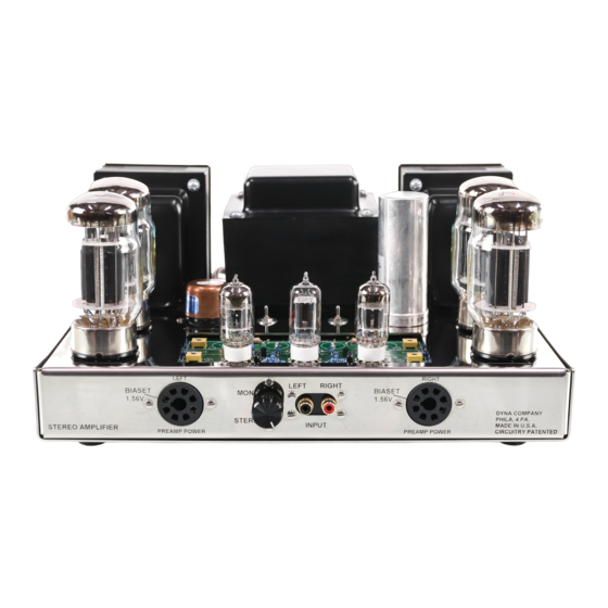
VTA ST-120 with CCS driver board amp KIT assembly manual
Congratulations on your purchase of the VTA ST-120 amp kit. Every effort has been made to give you
the finest sounding, most reliable and best looking 60 watt per channel tube amplifier kit presently
available. Your VTA amp kit features the following items which are all upgrades from the original Dynaco
kits.
1. A new STAINLESS STEEL chassis that is identical in size, shape and markings to the older original
nickel plated steel frame. This chassis is NON-MAGNETIC and removes any magnetic interference effects
of a steel chassis on the audio circuitry.
2. Quality USA made A-260-120 custom wound output transformers which are interleaved/layer-wound
and incorporate high quality M-6 grain oriented laminations.
3. A more robust PA-060-120 power transformer rated at 120 volts, having 410-0-410 secondaries and a
450 milliamp current transfer capability.
4. All stainless steel screws with zinc plated kep nuts
5. Heat resistant Celanex™ octal tube sockets
6. An 80, 40, 30, 20 uF main power supply electrolytic cap.
7. An all triode VTA driver board made of mil-spec epoxy fiberglass. This board also contains an on board
bias supply for the output tubes.
8. Gold plated input and output terminals.
9. A dual choke system rated at 480 milliamps
10. Triode/pentode switches to allow the amp to run in two modes of operation
11. A supplementary cap module (SCM) with an ESL reduction capacitor
Your KIT comes with a very easy to follow instruction manual and a clear pictorial specific to the VTA
driver board. All you need to complete the kit is a soldering pencil, some rosin core solder, a screwdriver,
pliers and a wire cutter/stripper to build your own VTA ST-120. The kit takes about 10-12 hours to build
depending on your skill level and any previous experience with kit building.
List of Parts
1 - 16 gauge heavy duty stainless steel chassis frame with bottom cover
1 - VTA driver board with parts set
7 – Celanex™ octal tube sockets
7 - grounding lugs (in with tube sockets)
1 – USA made PA-060-120 power transformer
4 - hard rubber isolation washers for power transformer
2 - USA made A-260-120 custom interleave/layer wound output transformers
2 - C24-X chokes
1 - multi section (80, 40, 30, 20 uF) quadruple capacitor
1 - three lug terminal strip
1 - pair of gold plated RCA input jack jacks with mounting board
2 - pair of gold plated 3 post output binding posts with mounting board
1 - rubber grommet
1 - fuse post with 5 amp SLO-BLO fuse (inside the fuse holder)
2 – 11 amp rated SPST slide switches
1 - 13 amp rated AC power cord
2 - .022 Mfd 100 volt capacitors
4 - 1000 ohm 1 watt resistors
4 - 10 ohm 2 watt bias resistors
1 - 4.7K ohm 3 watt resistor for quad cap
1 – Supplementary Cap Module (SCM)
1 – ESL reduction capacitor
1 - hardware kit for amp
1 - 22 foot coil of 20 gauge tinned solid core copper wire
1 – triode/pentode kit (2 DPDT switches, two 2 lug terminal strips, 4 X 100 ohm 1 watt resistors)
OPTIONAL > One tube set – 4 X 6550 output tubes, 3 X 12AU7 (or 12BH7, 5963, 6189, 5814), 1 X 5AR4
rectifier
Advertisement

Summary of Contents for tubes4hifi VTA ST-120
- Page 1 All you need to complete the kit is a soldering pencil, some rosin core solder, a screwdriver, pliers and a wire cutter/stripper to build your own VTA ST-120. The kit takes about 10-12 hours to build depending on your skill level and any previous experience with kit building.
- Page 2 Optionally painting the transformers Power and output transformers come from the factory with minor surface imperfections. You may, as an option, paint your transformers for a better appearance. (recommended) To most people a semi-gloss paint looks best on transformers. Use a spray can – don’t brush it on.
- Page 3 INSTRUCTIONS NOTE – You may or may not want to construct the VTA driver board BEFORE or AFTER you attach the chassis parts. If you wish to construct the VTA driver board at this time skip ahead to the VTA driver board instructions which are inside the VTA package and proceed with its construction.
- Page 4 B. Hold the strip with the grounded lug that attaches to the chassis towards your RIGHT - The lug closest to you is lug 1 and the next four lugs are lugs 2, 3, 4 and 5. C. Connect one 330K 1 watt resistor (found in SCM bag) between lugs 1 and 2 - have the resistor straight in line with the terminal strip and not on the side of the lug.
- Page 5 14. Remove the outside nut and larger flat washer from the switch. The smaller flat washer goes against the INSIDE of the chassis. Place the larger flat washer on the chassis TOP and nut on top of the flat washer. On the inside of the chassis make sure that the six terminals on the switch face from the front to the back of the amp so that the switch toggle on the top may be switched from FRONT to BACK and not side to side.
- Page 6 BLUE/WHITE wire from the LEFT OUTPUT TRANSFORMER to pin 3 of V2. Connect the BLUE wire from the RIGHT OUTPUT TRANSFORMER to pin 3 of V6. Connect the BLUE/WHITE wire from the RIGHT OUTPUT TRANSFORMER to pin 3 of V7. This is an incomplete VTA ST-120 manual...
- Page 7 Triode/Pentode switch pictorial NOTE: Disregard any pin number markings on the switches themselves and use the pin numbers listed below.
Need help?
Do you have a question about the VTA ST-120 and is the answer not in the manual?
Questions and answers