Advertisement
Quick Links
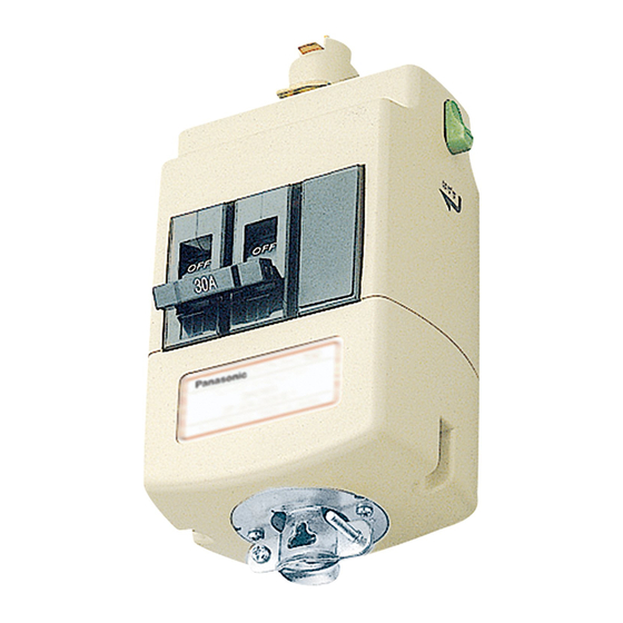
取扱説明書
■ご使用前にこの取扱説明書を必ずお読みのうえ、正しくお使いください。
■本製品のトラブル処理・増設などのメンテナンス作業は電気工事業者に依頼してください。なお、 その際には必ず本取扱・施工説明書を
お渡しください。
■この取扱説明書は必ず保管してください。
●ターミナルプラグの増設の際には、 結線作業が必要なため、 電気工事士の資格が必要です。
●ファクトライン100から30への分岐接続のように、分岐回路として使用するターミナルプラグの着脱・移設には電気工事士の資格が必要です。
●分岐回路ではなく、 直接負荷機器を接続して使用するターミナルプラグの着脱・移設、 ならびにコンセントプラグの増設は電気工事士の
資格がなくても行えます。
ご注意
プラグ類の着脱・移設・増設の際には、 必ず電源を切ってから行ってください。
ファクトライン100 ・ 60には寿命があり、標準的な使用期間は10年です。使用条件、使用場所で進行が異なりますが、毎年劣
化が進行します。当社では、 品質、 信頼性の向上に努めていますが、 劣化により最終的に継続的使用が困難な状態が生じますので、
早めの点検 ・ 交換をおすすめします。長くご使用いただくために、お客さまご自身で『安全チェックシート』に基づき最低年に
1回必ず定期点検してください。点検において異常がありましたら、電気工事士に処置を依頼してください。また3年に1回は
電気工事士による点検を受けてください。点検とともに以下のことを必ずお守りください。
人への危害、財産の損害を防止するため、必ずお守りいただくことを説明しています。
●製品の分解、改造は絶対におこなわない
感電 ・ 火災 ・ 落下の原因になります。
●ファクトライン100 ・ 60の本体に専用器具以外
を取り付けたり、専用器具以上の重量(ハンガー
吊り下げ許容荷重20 kg)をかけない
落下のおそれがあります。
●白熱球など高温となる照明器具を取り付けない
火災の原因になります。
●急激な温度変化で結露が生じるおそれのある場所
では使用しない
感電 ・ 火災の原因になります。
●一般屋内専用のため湿気の多い場所 ・ 振動のある
場所 ・雨の吹き込みを受ける場所 ・水気のある場
所 ・ 腐食性ガスの発生する場所、油煙の上がる場
所 ・ ヒーターの上部など熱の影響を受ける場所な
どでは使用しない
感電 ・ 火災 ・ 落下の原因となります。
●ファクトライン100 ・ 60本体にプラグを取り付
けた状態でスライドさせない
接触不良により、火災の原因になります。
●ファクトライン100 ・ 60の100 V専用プラグ類
は、アースの取り方や寸法が異なるため、ファク
トライン30に使用しない。ファクトライン30の
プラグ類も同様に、ファクトライン100 ・ 60の
2P 20 A回路には使用しない
感電 ・ 火災の原因になります。
●プラグの電線を引っ張らない
火災 ・ 落下の原因になります。
〒571-8686 大阪府門真市大字門真1048番地 TEL. (06) 6908-1131 〈代表〉
2013
©
ファクトライン 100・ 60
安全上のご注意
パワー機器ビジネスユニット
必ずお守りください
●異常が生じたら速やかに電源を切り、電気工事士に処置
を依頼する(その際には必ず取扱説明書を渡す)
守らないと、感電 ・ 火災 ・ 落下の原因になります。
●必ず表示された定格電圧、負荷容量以内で使用する
守らないと、感電・火災の原因になります。
●プラグは、許容荷重以下で使用する
守らないと、落下の原因になります。
●点検の際は、必ず電源を切ってからおこなう
守らないと、感電の原因になります。
●地震の発生後は変形、破損の有無や取付状態を確認し、
異常がある場合は電源を切り、電気工事士に処置を依
頼する
守らないと、感電・火災・落下の原因になります。
●周囲温度が- 10 ℃~ 40 ℃の範囲で使用する
範囲を超えて使用すると、焼損、火災の原因になります。
●プラグは正しい向きで取り付ける
逆向きに取り付けると、感電 ・ 火災 ・ 落下の原因になります。
●コンセントプラグ ・ リーラーコンセントプラグのコンセ
ントに直接荷重が加わらないようにする
守らないと、感電 ・ 火災 ・ 落下の原因になります。
●本製品を用いて情報伝達に使用する場合、 機種によっては、
本体相互の接続部分などで信号減衰が起こり、 伝送性能
が低下する場合があります
●ファクトライン100 ・ 60には寿命があり、 標準的な使
用期間は10年です。 外観に異常がなくても内部の劣化は
進行しているため点検交換する
点検せずに長期間使い続けると、感電 ・ 火災 ・ 落下の原因になり
ます。
保管用
DH2311-T17
TP0109-70317
Advertisement

Related Manuals for Panasonic Factory Line 100-60


Summary of Contents for Panasonic Factory Line 100-60
- Page 1 保管用 取扱説明書 ファクトライン 100・ 60 ■ご使用前にこの取扱説明書を必ずお読みのうえ、正しくお使いください。 ■本製品のトラブル処理・増設などのメンテナンス作業は電気工事業者に依頼してください。なお、 その際には必ず本取扱・施工説明書を お渡しください。 ■この取扱説明書は必ず保管してください。 ●ターミナルプラグの増設の際には、 結線作業が必要なため、 電気工事士の資格が必要です。 ●ファクトライン100から30への分岐接続のように、分岐回路として使用するターミナルプラグの着脱・移設には電気工事士の資格が必要です。 ●分岐回路ではなく、 直接負荷機器を接続して使用するターミナルプラグの着脱・移設、 ならびにコンセントプラグの増設は電気工事士の 資格がなくても行えます。 ご注意 プラグ類の着脱・移設・増設の際には、 必ず電源を切ってから行ってください。 ファクトライン100 ・ 60には寿命があり、標準的な使用期間は10年です。使用条件、使用場所で進行が異なりますが、毎年劣 化が進行します。当社では、 品質、 信頼性の向上に努めていますが、 劣化により最終的に継続的使用が困難な状態が生じますので、 早めの点検 ・ 交換をおすすめします。長くご使用いただくために、お客さまご自身で『安全チェックシート』に基づき最低年に 1回必ず定期点検してください。点検において異常がありましたら、電気工事士に処置を依頼してください。また3年に1回は 電気工事士による点検を受けてください。点検とともに以下のことを必ずお守りください。 安全上のご注意 必ずお守りください 人への危害、財産の損害を防止するため、必ずお守りいただくことを説明しています。 ●製品の分解、改造は絶対におこなわない ●異常が生じたら速やかに電源を切り、電気工事士に処置 を依頼する(その際には必ず取扱説明書を渡す) 感電...
- Page 2 施工説明書 ファクトライン 100・ 60 ■施工前にこの施工説明書を必ずお読みのうえ、 正しく施工してください。 ■この商品の施工には電気工事士の資格が必要です。施工は必ず電気工事士に依頼してください。 安全上のご注意 必ずお守りください 人への危害、財産の損害を防止するため、必ずお守りいただくことを説明しています。 ●製品の分解、改造は絶対におこなわない ●この製品は、 電気設備技術基準 (省令) および内線規程に 従い施工する。 電源の一次側には適正な過電流遮断器を 感電・火災・落下の原因になります。 ●エアコンの風が直接当たるなど急激な温度変化で 使用する。電線は、分岐回路を保護する過電流遮断器・ 結露が生じるおそれのある場所などでは使用しない 定格電流に適したサイズのものを選定する 感電 ・ 火災 ・ 落下の原因になります。 守らないと、感電・火災・落下の原因になります。 ●燃焼性ガスの雰囲気では使用しない ●施工の際は、必ず電源を切ってからおこなう 爆発の原因となります。 守らないと、感電の原因になります。 ●ファクトライン 60・100 本体にかかる荷重は、許容 荷重値以下とする。 守らないと、落下の原因になります。 ●一般屋内専用です。湿気の多い場所 ・ 振動のある ●周囲温度が-...
- Page 3 ファクトライン100・60の安全チェックシート&メンテナンス表 ●1年に1回以上は安全チェックシートに基づき自主点検してください。異常があれば速やかに電気工事士に処置を依頼してください。 ●竣工時とその後3年に1回以上は電気工事士による点検をお受けください。 ●設置から10年後以降もお使いになる場合は、最低でも1年に1回以上は必ず電気工事士による点検をお受けください。 また設置から15年後以降は使用を速やかに中止し、交換してください。 件 名 点検日 年 月 日 点検者 ○:要交換 ○:異常なし ●:交換済 点検 ●異常時の処置・対策は必ず電源を切り、 処置 結果 電気工事士がおこなう △:要調整 ×:異常あり 守らないと感電・火災・落下の原因となります。 ▲:調整済 ■安全チェックシート(自主点検) : 1年に1回以上 点検 2.変色確認箇所 点検項目 結果 使用期間が10年以上でないか 使用 期間 使用期間が15年以上でないか ファクトライン 100・60 に結露が発生し 本体 ていないか ファクトライン 100・60 本体の内部に変 色やこげが発生していないか...
- Page 4 ファク トライン100 ・ 60施工方法 施工上のご注意 本体の取り付け方向とプラグの向きの関係 ●本体の取り付け方向はプラグの向きを決めてから施工してください。 ●本体はプラグの表側と本体の極性表示を同一方向にして施工してくだ さい。 極性表示 (接地側) (フィー ドインキャ ップはプラグの表側からみて、 左側になります。 ) (グ リ ー ンライ ン) 給電位置 (フィー ドイン) とプラグの向きの関係 プラ グの表側 (ブレーカーのハン ドル 標準施工 ま たは銘板側) フィー ドインキャ ップは本体のジョイナピンのない側に接続します。 極性表示 (接地側) (下か ら見た図) (グ...
- Page 5 ハンガーの取り付け .ハンガーの取り付けピッチは1.5 m以下にする。 ●本体が1mの場合は、 ハンガーは1か所以上取り付けてください。 .吊りボル トは造営材に確実に固定する。 支持間隔1.5m以下 吊りボル ト ハンガー 注 意 振れ止め金具 長い吊りボル トを使用する場合は、 振れ止め金具 ● ハンガー DL741Yにて振れ止めする。 (ボル トな し) 金具 本体が蛇行しないよう、 ハンガーのセンターをそろ ● える 必ず守る 守らないと、 落下の原因になります。 本体の取り付け .本体上面の角部でハンガーフック部を押し開ける。 .そのまま本体を押し上げてリブ部をフック部に引っかける。 ハンガー (ハンガー<ボル トなし>を用いる場合も同様にして取り付け られます。 ) フ ッ ク部 注 意...
- Page 6 直付ハンガーの取り付け .ハンガー取り付けピッチは1.5 m以下にする。 ナッ ト ●本体が1mの場合は、 ハンガーは1か所以上取り付けてください。 〔M5〜M6 (供給外) 〕 .ハンガーの取り付け位置は、 ハンガーに刻印したセンターマ ークに合わせてセッ トする。 センターマーク 造営材 .取り付けねじはM5〜M6を使用し、 造営材に確実に固定する。 φ6.2穴 .ハンガーの取り付け面の高さレベルがでていない時はスペ ーサなど (供給外) で調整する。 注 意 取り付けね じ 〔M5〜M6 (供給外) 〕 ハンガーを取り付けるときは、 確実に取り付ける ● 支持間隔1.5m以下 守らないと、 落下の原因になります。 必ず守る ナッ ト 造営材 スキマ2.8 mm 〔M5〜M6 (供給外) 〕 ハンガー...
- Page 7 耐震補強金具の取り付け 本体の接続 .ジョイナのセッ トねじをゆるめて本体に差し込む。 耐震補強金具の取り付け .本体のジョイナピンを確実に接続する。 .耐震補強金具とハンガーの中心を合わせ、 耐震補強金具の .ジョイナのセッ トねじを確実に締めつける。 a部にハンガーのb部をはめ込む。 ご注意 ハンガー 本体相互の接続にはジョイナを使用してください。 ● 注 意 部 本体は、 突き合わせて確実に接続する ● 接続不良おそれがあります。 切欠部 セッ トねじは確実に締め付ける ● 必ず守る 部 守らないと、 感電 ・ 火災の原因になります。 耐震補強金具 ジョ イナピン 極性表示 (接地側) (グ リ ーンライ ン) .どちらか片方のツメ部(c)を の方向に力を入れ、...
- Page 8 フィー ドインキャ ップの取り付け ご注意 本体との接続 本体にフィー ドインキャ ップを差し込み、 セッ トねじを締めて 電源(B)の接続は本体の極性表示側を必ず接地側としてください。 ● 端末加工や補助本体(DH2310)を使用して、極性を変える場合は、 ● 固定する。 フィードインの端子の並びは逆になります。 電線(A)は14〜38 mm を使用してください。 ● 電線(B)は1.6〜2mmの単線、または2〜3.5 mm のより線を使用 ● 電線の接続 してください。 リモコンブレーカ付ターミナルプラグをご使用になる場合は、操作電 ● .電線 (A)の被履を18〜20 mmの長さだけはぎ取り、 圧は100 Vとしてください。(200 Vでは使用できません) アース線を圧着端子または巻き締めによって、アース端子ねじに接続 端子ねじ (A) をゆるめて端子に差し込み、 端子ねじ (A) ● してください。 を締め付け確実に接続する。結線後、相識別ラベルを 端子ねじ(A)近くに貼り付けてください。 ( 締付トルク 5.0 N ・...
- Page 9 ブレーカ付フィー ドインキャ ップの取り付け ご注意 本体との接続 電源(B)の接続は本体の極性表示側を必ず接地側としてください。 ● 本体にブレーカ付フィードインキャップを差し込み、セット 端末加工や補助本体(DH2310)を使用して、極性を変える場合は、 ● ねじを締めて固定する。 フィードインの端子の並びは逆になります。 電線(A)は14〜38 mm を使用してください。 ● 電線(B)は1.6〜2.0 mmの単線、または2.0〜3.5 mm のより線を ● 電線の接続 使用してください。 リモコンブレーカ付ターミナルプラグをご使用になる場合は、操作電 ● .電線 (A)被履を13〜15 mmの長さだけはぎ取り、圧 圧は100 Vとしてください。(200 Vでは使用できません) 着端子を取り付ける。 アース線を圧着端子または巻き締めによって、アース端子ねじに接続 ● してください。 .ブレーカの端子板に電線(A)を確実に接続する。結線後、 相識別ラベルを端子ねじ(A)近くに貼り付けてくださ い。 ( 締付トルク5.0 N ・ m〜7.0 N ・ m) .電線 (B)の被履を10〜12 mmの長さだけはぎ取り、 端子ねじ...
- Page 10 センターフィー ドインジョイナの取り付け ご注意 本体との接続 電源(B)の接続は本体の極性表示側を必ず接地側としてください。 ● 本体にセンターフィードジョイナを差し込み、セットねじ 端末加工や補助本体(DH2310)を使用して、極性を変える場合は、 ● を締めて固定する フィードインの端子並びは逆になります。 電線(A)は14〜38 mm を使用してください。 ● 電線(B)は1.6〜2mmの単線、または2〜3.5 mm のより線を使用 ● 電線の接続 してください。 リモコンブレーカ付ターミナルプラグをご使用になる場合は、操作電 ● 圧は100 Vとしてください。(200 Vでは使用できません) .電線 (A) を圧着端子によって端子ねじ (A) でターミナルに アース線を圧着端子または巻き締めによって、アース端子ねじに接続 ● 締め付け、 確実に接続する。 結線後、 相識別ラベルを端子 してください。 ねじ (A) 近くに貼り付けてください。 ( 締付 トルク : 5.0 N・ m〜7.0 N・m)...
- Page 11 ターミナルプラグAの取り付け 30Aプラグの場合 極性表示 (接地側) 電線の接続 (グ リ ー ンライ ン) .セッ トねじを抜き、 カバーを外す。 .ケーブルクランプの止めねじをゆるめ、 電線をカバーに挿入する。 極性表示 (接地側) アース .電線を圧着端子または巻き締めによって端子板に接続する。 (グ リ ー ンライ ン) 結線後、相識別ラベルを端子ねじ近くに貼り付けてくださ 3 右に90° 回転させる い。 ( 締付トルク2.5 N ・ m〜3.5 N ・ m) .カバーをボディに挿入して、 セッ トねじで固定する。 2 差 し込む .ケーブルクランプの止めねじを締め付けて、 電線を固定する。 ター...
- Page 12 ブレーカ付ターミナルプラグの取り付け 20 ・ 30Aプラグの場合 3 右に90°回転させる アース 極性表示 (接地側) 極性表示 (接地側) 電線の接続 1 極性を合わせる (グ リ ー ンライ ン) (グリーンライ ン) 2 差し込む .セッ トねじを抜き、 カバーを外す。 .ケーブルクランプの止めねじをゆるめ、 電線をカバーに挿入する。 レバー ボディ (グリーン色) .電線を圧着端子 (適合圧着端子 : 5.5−5) 、 またはより線 の場合は振り分けて差し込んで端子板に接続してくださ アース端子板 端子ね じ い (締付 トルク:2.5 N•m 〜 3.5 N•m) 。 (M5)...
- Page 13 照明器具の取り付け クランプと照明器具用プラグの固定 〈 クランプ 〉 クランプは、 右図のように照明器具のボル ト穴に挿入し、 ロックナッ トで締め付けて固定する。 照明器具用プラ グ 〈照明器具用プラグ〉 <プラ グ側> 照明器具用プラグは、 右図のように電源穴に挿入して、 ロッ クナッ トで締め付け、 固定する。 照明器具用プラ グ 注 意 <クラ ンプ側> 取り付け穴 電線をねじなし端子に接続する場合は棒型圧着端子を ● (φ20.0) 使用する 接続不良による火災のの原因になります。 ロックナッ トは確実に締め付ける ● (締付 トルク : 1.5±0.1 N ・ m) 必ず守る ...
- Page 14 コンセン トプラグの取り付け プラグの取り付け ●プラグのレバー (グリーン色) を本体の極性表示 (グリーンラ 極性表示 (接地側) イン) に合わせて差し込み、 右に90° 回転させる。 (グ リ ー ンライ ン) 注 意 アース 極性表示 (接地側) プラグの逆向き接続しない ● (グ リ ー ンライ ン) ファク トライン30用プラグ (オレンジレバー) は使用 ● しない 3 右に90° 回転させる 必ず守る 守らないと、 感電 ・ 火災の原因になります。 2 差...
- Page 15 リーラーコンセン トプラグの取り付けとご使用方法 リーラーコンセントの取り付け ●プラグのレバー (グリーン色) を本体の極性 (グリーンライ ン) に合わせて差し込み、 右に90° 回転させる。 極性表示 (接地側) 注 意 (グ リ ー ンライ ン) プラグの逆向き接続しない ● ファク トライン30用プラグ (オレンジレバー) は使用 極性表示 (接地側) ● アース しない (グ リ ー ンライ ン) 必ず守る 守らないと、 感電 ・ 火災の原因になります。 3 右に90°...
- Page 16 L字形の施工 ファク トライン100 ・ 60を L字形に施工する場合は、 ジョイナ L を使用する。 〈ファク トライン100の場合〉 ■L字形施工 フィードインキャップ ●ジョイナ Lの両端に本体接続用のジョイナピンが付いてい るため、 本体のジョイナピン側は接続できません。 本体を 図のようにジョイナピン側で40 mm切断する。 本体 ご注意 40 mm切断 本体の切断加工が必要です。 ● ジ ョ イナL ダク トの極性を合わせてください。 ● エ ン ドキ ャ ッ プ 本体 ■加工概要 ●切断加工方法 この位置を金のこで切断してください。 ●本体のリブ(3カ所)をφ3 mmのキリ(深さ10〜11 ...
- Page 17 L shaped installation To install Factory line 100 or 60 in a shape of L , use the Joiner L. 〈Factory Line 100〉 The Factory Line 100 duct needs to be cut. ■ L-shaped installation ●Since joiner pins used for the duct connection are provided on each end of the Joiner L, the joiner pins side of the duct is not available for the connection. Feed-in cap Consequently, cut the duct on the joiner pins side by 40 mm in length as shown in the figure. Notes 40 mm cutting The Factory Line duct needs to be cut. ● Joiner L Adjust the polarity of the duct. ● End cap ●Cut the ribs (in three places) of the duct using a drill of φ3 mm in diameter (10 to 11 mm in ●Cutting the duct depth). ●Thoroughly remove burrs and chips from the cut Cutting position surface. (Be sure to chamfer the inner surface of the conductors in particular.) Notes Duct Using an power saw may cause insulating coating to peel ● or burn. Joiner pin To cut the ribs, prevent the exposure of the conductors and ● cores. Cut by 10 or 11 mm in length from the cut surface.
- Page 18 Procedure for mounting and using reeler outlet plug Mounting reeler outlet ●To mount the reeler outlet, pull down the plug lever, and then rotate it clockwise by 90 degrees. Polarity indidication (Grounding side) Caution (Green line) Do not mount the clamp in the opposite direction. ● Doing so may result in an electric shock or a fire. Polarity indidication Do not use plugs (with an orange lever) for Factory Line 30. ● Ground (Grounding side) Doing so may result in an electric shock or a fire. (Green line) 3 Rotate90° clockwise Dismounting plug 2 Insert ●Pull up the plug lever, and then rotate it counterclockwise by 90 degrees. 1 Adjust the polarity Lever (Green) Outlet Up-and-down operation of outlet Terminal pulg B Push (The outlet can expand and contract in the range of button approximately 80 to 180 cm from the mounting surface.) ●Press the pushbutton to slightly pull up the main body of the outlet. It stops in a position in which the pushbutton is released. ●To return the main body to the original position, Cord hook press and hold the pushbutton to push up the main body to a position to which you want to return it. ...
- Page 19 Mounting outlet plug Mounting plug ●Put the outlet plug lever in the duct in line with Polarity indication its polarity indication (green line), and then (Grounding side) rotate the plug clockwise by 90 degrees. (Green line) Caution Ground Polarity indication Do not mount the clamp in the opposite direction. ● (Grounding side) Doing so may result in an electric shock or a fire. (Green line) 3 Rotate90° clockwise Do not use plugs (with an orange lever) for Factory Line 30. ● 2 Insert Doing so may result in an electric shock or a fire. 1 Adjust the polarity Dismounting plug ●プラグのレバーを引き下げて、 左に90°回転させる。 Lever (Green) ●Pull up the plug lever, and then rotate it Outlet plug counterclockwise by 90 degrees. Mounting terminal plug B Connecting electrical cables Setscrew Terminal screw .Remove the setscrews, and then dismount the cover. (M4) .Unfasten the cable clamp securing screw, and Body then put the electrical cable into the cover. Grounding ...
- Page 20 Mounting Lighting fixture ※ The clamp and the Lighting plug come Fixing clamp and Lighting plug with a set of Lighting fixture. 〈Clamp〉 As shown in the figure, put the clamp in the hole for bolt in the Lighting fixture, and then fasten the locknut to fix the clamp. Lighting fixture plug <Plug side> 〈Lighting plug〉 As shown in the figure, put the Lighting plug in the hole for power supply cable, and then fasten the locknut to fix the plug. Lighting fixture plug <Clamp side> Caution Mounting hole To connect the cable to unthreaded terminal, use bar ● (φ20.0) type crimp-style terminal. Not doing so may result in faulty cable connection, thus leading to a fire. Tighten the locknut securely ● (Tightening torque: 1.5±0.1N ・ m) Wave washer (Failure to do so may result in dropping.) Lighting fixture Claw washer Locknut...
- Page 21 Mounting a circuit breaker equipped terminal plug Mounting 20 ・ 30A plug 3 Rotate90° clockwise Ground Polarity indication Polarity indication (Grounding side) Connecting cables 1 Adjust the polarity (Grounding side) (Green line) (Green line) 2 Insert .Remove the setscrews, and then dismount the cover. .Unfasten the cable clamp securing screw, and then Body Lever put the cables in the cover. (Green) Grounding .Connect the cable to the terminal block. terminal block When using a stranded-conductor cable or a crimp-style terminal (applicable Grounding crimp-style ...
- Page 22 Mounting terminal plug A Mounting 30A plug Polarity indication (Grounding side) (Green line) Connecting cables Polarity indication Ground .Remove the setscrews, and then dismount the cover. (Grounding side)(Green line) .Unfasten the cable clamp securing screw, and then put the cables in the cover. 3 Rotate90° clockwise .Connect the cables to the terminal block by the use of a crimp-style 2 Insert terminal or winding the cable around the terminal, respectively. After connecting,post the polarity indication label near the terminals 1 Adjust the polarity screw.(Tightening torque 4.0 N ・ m 〜 5.0 N ・ m) Terminal .Mount the cover to the main body on the terminal Body plug A side, and then fix it with the setscrews. Grounding Lever .Fasten the securing screw of the cable clamp to fix the cables. terminal block (Green) Caution Grounding Terminal screw terminal screw (M5) Securely fasten the terminal screws. ● Terminal Cover Do not use plugs (with an orange lever) for Factory Line 30.
- Page 23 Installing a center feed-in joiner Notes Connecting to Factory Line duct To connect the cable (B), be sure to put the polarity marking ● side of the duct on the grounding side. Put a center feed-in joiner in the duct, and then The relation between the duct (conductor) and the terminal ● fasten setscrews to fix the joiner. screws is as shown in the figure above. However, if the polarity is changed by processing the duct end or using the auxiliary duct unit (DH2310), the arrangement of terminals of Connecting the wires the center feed-in joiner will be inverted. The cable (A) must be 14 to 38 mm in size. ● The cable (B) must be a single-conductor cable of 1.6 to 2.0 mm .Fasten the terminal screw (A) to securely ● in size or a stranded-conductor cable of 2 to 3.5 mm in size. connect the electricai cable (A) by the To use a terminal plug with a remote-control circuit breaker ● crimp-style terminal.After connecting,post the polarity equipped, apply a 100V operating voltage. (200V operating voltage is not available for this product.) indication label near the screw terminals. Connect a grounding cable to the grounding terminal screw ● by the use of a crimp-style terminal or winding the cable (Tightening torque 5.0 N ・ m 〜 7.0 N ・ m) around the terminal. .Strip the sheath of the electrical cable (B) by 10 to 12 mm in length, unfasten the terminal ...
- Page 24 Installing feed-in cap with a circuit breaker equipped Note Connecting to Factory Line duct To connect the cable (B), be sure to put the polarity ● Put a feed-in cap with a circuit breaker equipped in the indication side of the Fact-line duct on the grounding side. Factory Line duct, and then fasten the setscrew to fix the cap. if the polarity is changed by processing the duct end or ● using he auxiliary duct unit (DH2310), the arrangement of Connecting cables terminals of the feed-in cap will be inverted. The cable (A) must be 14 to 38 mm in size. ● The cable (B) must be a single-conductor cable of 1.6 to ● .Strip the sheath of the cable (A) by 13 to 15 mm in length, and 2.0 mm in size or a stranded-conductor cable of 2 to 3.5 then mount a crimp-style terminal to the electrical cable (A). in size. To use a terminal plug with a remote-control circuit breaker ● .Securely connect the electrical cable (A) to the equipped, apply a 100V operating voltage. (200V operating terminal block of the circuit breaker. voltage is not available for this product.) Connect a grounding cable to the grounding terminal screw After connecting,post the polarity indication label near the ● by the use of a crimp-style terminal or winding the cable screw terminals.(Tightening torque 5.0 N ・ m 〜 7.0 N ・ m) around the terminal. .Strip the sheath of the electrical cable (B) by 10 to 12 mm in length, unfasten the terminal screw (B) to put the electrical cable (B) under the washer, and then fasten the terminal ...
- Page 25 Installing feed-in cap Note Connecting to Factory Line duct To connect the cable (B), be sure to put the polarity marking ● Put a feed-in cap in the Factory Line duct, and then side of the duct on the grounding side. fasten the setscrews to fix the cap. if the polarity is changed by processing the duct end or ● using he auxiliary duct unit (DH2310), the arrangement of terminals of the feed-in cap will be inverted. Connecting cables he cable (A) must be 14 to 38 mm in size. ● The cable (B) must be a single-conductor cable of 1.6 to ● .Strip the sheath of the electrical cable (A) by 18 to 20 mm 2.0 mm in size or a stranded-conductor cable of 2 to 3.5 in size. in length, unfasten the terminal screw (A) to put the To use a terminal plug with a remote control circuit breaker, ● electrical cable (A) in the terminal, and then fasten the apply a 100V operating voltage. (200V operating voltage is not available for this product.) terminal screw (A) to securely connect the electrical cable (A). Connect a grounding cable to the grounding terminal screw ● After connecting,post the polarity indication label near the by the use of a crimp-style terminal or winding the cable around the terminal. screw terminals.(Tightening torque 5.0 N ・ m 〜 7.0 N ・ m) .Strip the sheath of the electrical cable (B) by 10 to 12 mm in length, unfasten the terminal screw (B) to put the electrical cable (B) under the washer, and then fasten the ...
- Page 26 Mounting seismic strengthening brackets Connecting Factory Line ducts .Unfasten the joiner setscrews, and then fit it to Mounting seismic strengthening bracket one Factory Line duct. .Securely fit the joiner pins of the Factory Line .Align the center of seismic strengthening duct to the other Factory Line duct. bracket with that of a hanger, and then fit the .Securely fasten the joiner setscrews. part b of the hanger in the part a of the seismic Note strengthening bracket. To connect Factory Line ducts, use a joiner. ● Hanger Caution Connect the ducts so that they butt securely up each other. ● Securely fasten the joiner setscrews. ● Notch Not doing so may result in an electric shock or a fire. Seismic strengthening bracket Joiner pin Polarity indication .Apply force in the direction of to push one (Grounding side) tab (c) in the notch of the hanger with your (Green line) thumb until you feel a click. Polarity indication (Grounding side) .Subsequently, push the other tab (d) in the (Green line) notch of the hanger in the same manner.
- Page 27 Installation of direct-mounted type hangers .Mount the hangers at the spacing of shorter than 1.5 m. ●When the main body is 1 m in length, set up the 〔M5〜M6 ( out of supply)〕 hangers at two or more points. .Align the hanger mounting position with a center Center marking Building structure mark punched on each hanger. φ6.2hole .Fix the hanger securely to the building structure using M5 or M6 screws. .If the hanger mounting surfaces are not flash with each other, level the surfaces using spacers or Mounting screw else (that are not included in the scope of supply). 〔M5〜M6 ( out of supply)〕 Caution Support intervals: Shorter than 1.5 m Building structure 〔M5〜M6 ( out of supply)〕 Gap 2.8 mm Hangers must be securely fixed. ● Not doing so may cause them to Hanger Mounting screw 〔M5〜M6 ( out of supply)〕 Installation of the duct 〔M5〜M6 ( out of supply)〕 Building structure .Push to open a hook on one side using the upper ...
-
Page 28: Hanger Installation
Hanger installation .Mount the hangers at the spacing of shorter than 1.5 m. ●When the main body is 1 m in length, set up the hangers at two or more points. Support intervals: Shorter than 1.5 m .Fix hanger bolts securely to building structure. Caution Fix hanger bolts(M10) Use long hanger bolts, mount these bolts using sway ● braces (DL741Y). To prevent the ducts from meandering, align the ● hanger centers. Not doing so may cause the hangers to drop. Hanger Sway braces Hanger (without bolt) Installation of the duct .Push to open the hook part using the upper corner of the duct. .Directly push up the duct, and then hitch the Hanger rib part on the hook part. To use hangers that do not use hanger bolts, mount them in the same way as that aforementioned. Hook part Caution Hangers must be securely fixed. ● Not doing so may cause them to drop. Rib part Removal of the duct Hanger .Insert a flat-blade screwdriver in a notch of a hanger, and then pull it up in the direction of an arrow. Subsequently, disengage the hook part of the hanger from the rib part of the duct. .Dismount the duct downwards. -
Page 29: Installation Procedure
Installation Procedure Precautions on installation Duct Relation between a direction in which the Factory Line duct is mounted and direction of plug ●Determine a direction in which the duct is mounted after determining the direction of plug. ●Install the duct pointing the font side of the plug and the polarity marking of the duct to the same direction. Polarity indication (The feed-in cap is located on the left when viewed from the front side of the plug.) (Grounding side) (Green line) Relation between the power feed position (feed-in) and the direction of plug Front side of plug ( ) The side of breaker's Standard installation handle or nameplate Connect the feed-in cap to the side with no Polarity indication joiner pins equipped of the duct. (Grounding side) Duct (Figure viewed from the bottom) (Green line) Feed-in cap End cap Joiner pins Front side of plug To connect the feed-in cap to the joiner pins side of the duct: Factory Line 100 (Figure viewed from the bottom) Front side of plug Cut by 40 mm. - Page 30 Safety Check Sheet & Maintenance Sheet ● At least once a year, please do self-inspection due to safety check sheet. If any abnormality occurs, immediately contact electrical worker. ● Receive the check by the specialist in the construction shop etc. once every three years. ●...
-
Page 31: Safety Precautions
Factory Line 100・60 Installation Manual ■ Be sure to read this Instruction Manual before installation, and then properly install the product. ■ Installing this product requires the qualification as an electrical worker. Be sure to ask a contractor Safety precautions Be sure to observe the precautions fully The precautions describe what must be observed not to harm humans nor cause property damage. - Page 32 100・60. Even if abnormality is not found in externals, the check Not doing so may result in an electric shock or a fire. exchange is done internally because it is deteriorated Panasonic Corporation Power Components Business Unit 1048,kadoma,kadoma,osaka,571-8686,japan Telephone:+81-06-6908-1131 2013 ©...