Table of Contents
Advertisement
Advertisement
Table of Contents

Related Manuals for GeoMax Zipp02


Summary of Contents for GeoMax Zipp02
- Page 1 GeoMax Zipp02 User Manual Version 1.1...
- Page 2 The type and serial number of your product are indicated on the type plate. cation Enter the type and serial number in your manual and always refer to this infor- mation when you need to contact your agency or GeoMax authorised service workshop. Type: ______________________________________________ Serial No.:...
- Page 3 Important paragraphs which must be adhered to in practice as they enable the product to be used in a technically correct and efficient manner. Introduction Zipp02 | 3...
-
Page 4: Table Of Contents
Table of Contents Zipp02 | 4 Table of Contents In this manual Chapter Page Description of the System 1.1 Instrument Case 1.2 Instrument Components User Interface 2.1 Function of Buttons 2.2 Display Preparation before Measurement 3.1 Preparation of Battery 3.2 Erection of the Instrument 3.3 Leveling up of the Instrument... - Page 5 5.2 Circle Vial 5.3 Laser Plummet 5.4 Perpendicular of Vertical Hair of Reticle of Telescope 5.5 Collimation Error 5.6 Index Error of Vertical Circle Care and Transport 6.1 Transport 6.2 Storage 6.3 Cleaning and Drying Table of Contents Zipp02 | 5...
-
Page 6: Table Of Contents Zipp02
Table of Contents Zipp02 | 6 Safety Directions 7.1 General 7.2 Intended Use 7.3 Limits of Use 7.4 Responsibilities 7.5 Hazards of Use 7.6 Laser Classification 7.6.1 General 7.6.2 Laser Plummet 7.7 Electromagnetic Compatibility EMC Technical Data 8.1 Technical Data of the Instrument 8.2 Conformity to National Regulations... -
Page 7: Description Of The System
All the clamp knobs must be slightly tightened again after the instrument is in place in the case. Description of the System Zipp02 | 7... -
Page 8: Instrument Components
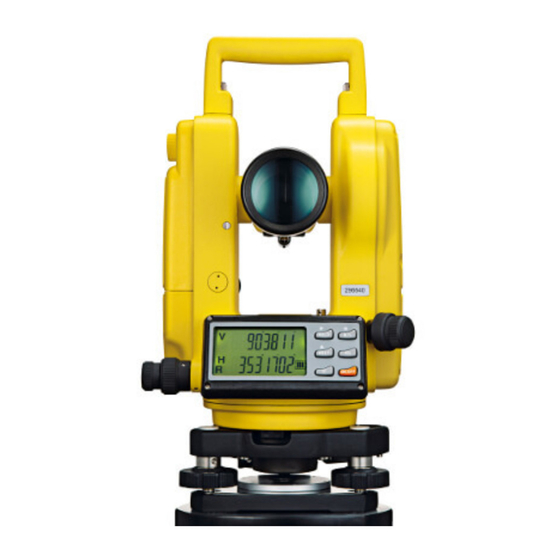
Description of the System Zipp02 | 8 1.2 Instrument Components 1. Screw of handle Instrument components part 2. Objective lens 1 of 2 3. LCD display I 4. Horizontal drive 5. Levelling screw 6. Handle 7. Laser plummet 8. Tribrach locking lever... - Page 9 1. Focusing knob Instrument components part 2. Eyepiece 2 of 2 3. Optical sight 4. LCD display II 5. Circular vial 6. Battery case 7. Vertical drive 8. Tubular vial Description of the System Zipp02 | 9...
-
Page 10: User Interface
User Interface Zipp02 | 10 2 User Interface 2.1 Function of Buttons 1. R/L button Description 2. HOLD button 3. V% button 4. 0SET button 5. ON/OFF button 6. Light button Buttons Button Function 1 Other ON/OFF Switch the instru- 1. - Page 11 1. Menu selection button in initial setting. left and right 2. One of the function buttons for entering increment of hori- into initial setting of the instrument. zontal angle 3. Plus number to change the time. reading User Interface Zipp02 | 11...
- Page 12 User Interface Zipp02 | 12 Button Function 1 Other Switch between 1. One of the function buttons for entering display of vertical into initial setting of the instrument. angle in angle unit 2. Button for confirmation after initial setting or as percentage of the instrument.
-
Page 13: Display
Date and time Shows the current date and time, according to the settings. Auto power off is displayed, when the auto power off function is "ON". Battery The battery symbol shows the current battery power level. User Interface Zipp02 | 13... -
Page 14: Preparation Before Measurement
Preparation before Measurement Zipp02 | 14 3 Preparation before Measurement 3.1 Preparation of Battery Checking electric Refer to "4.1 Start Up" on how to check the power status of the battery. quantity Before removal of any battery, the instrument must be switched off to avoid malfunction. - Page 15 2. Insert the plug of the charger to the charging port of the Ni-MH battery pack. The green light of the charger turns red, the charging process is started, after 3 to 4 hours when the red light turns green, it indicates that the charging process is finished. Preparation before Measurement Zipp02 | 15...
-
Page 16: Erection Of The Instrument
Preparation before Measurement Zipp02 | 16 3.2 Erection of the Instrument Erection of the 1. Stretch the tripod to a proper hight. instrument 2. Ensure that the measure point is exactly under the central hole of the tripod head. 3. Level up the tripod (this is very important when centering with plumb bob). -
Page 17: Centering
1. Turn the knob of the eyepiece of the optical plummet so that the reticle is in focus; turn the focusing knob so that the ground point a is in focus. Then, loosen the central screw to translate the whole instrument (be sure Preparation before Measurement Zipp02 | 17... -
Page 18: Collimation
Preparation before Measurement Zipp02 | 18 not to turn the instrument) so that the ground point coincides with the central point of the reticle. Retighten the central screw. 2. Perform precise leveling up of the instrument as described in "3.3 Leveling up of the Instrument"... -
Page 19: Initial Settings
3. Auto power off time 30 OFF NO OFF 4. Minimum display DSP 1 DSP 5 resulution 5. Tilt sensor switch TILT ON TILT OFF 6. Indication of position NO BEEP 90 BEEP of horizontal angle Preparation before Measurement Zipp02 | 19... - Page 20 Preparation before Measurement Zipp02 | 20 1. Press and hold HOLD button + 0SET button and Method of setting press ON/OFF button. 2. Release ON/OFF button when full character display appears and release HOLD + 0SET buttons when four beeps are heard.
- Page 21 • V TILT OFF: Turn off the tilt sensor 6. Inidication of horizontal angle • NO BEEP: Horizontal angle indicator disabled • 90 BEEP: Gives out beep when the instrument is close to 0°, 90°, 180° and 270° Preparation before Measurement Zipp02 | 21...
- Page 22 Preparation before Measurement Zipp02 | 22 Set Date & Time Press and hold LIGHT and 0SET button while turning on the instrument. The instrument shows ADJ2 and will switch automatically to the settings for date and time. Press HOLD to move between fields, R/L to increase, V% to...
-
Page 23: Operation Method
• If three bars are shown the battery is fully charged. • A flashing battery symbol indicates a low power status of the battery. Turn off the instrument and change to a new battery to avoid an automatic switch off by the instru- ment. Operation Method Zipp02 | 23... -
Page 24: Measurement Of Angle
Operation Method Zipp02 | 24 4.2 Measurement of Angle Observing in the The normal position of the telescope refers to observation with the object lens "Normal" and facing right ahead (the vertical encoder being on the left); the reverse position "Reverse"... - Page 25 ZEN==0 (Zenith 0°) ZEN==90 (Zenith 90°) 2. Compensation of the tilt sensor to vertical angle • The working range of the vertical tilt sensor is ±3’. Within this range the vertical read- ings will be corrected. Operation Method Zipp02 | 25...
- Page 26 Operation Method Zipp02 | 26 • If the inclination is greater than ±3’, the instrument will display as shown in the figure 3. Display of slope Press V% button, the vertical angle display is turned into slope display; press V% button, the vertical angle display is resumed.
- Page 27 • When HR is displayed, the angle increases with clockwise turning of the collimation unit. • When HL is displayed, the angle increases with counter-clockwise turning of the colli- mation unit. Operation Method Zipp02 | 27...
-
Page 28: Turning Off The Instrument
Operation Method Zipp02 | 28 3. Holding horizontal angle Press HOLD button, the horizontal angle will be held; the reading of the horizontal angle will remain unchanged even if the direction of colli- mation is changed. Press HOLD button again, the hold of hori- zontal angle is released. -
Page 29: Measuring Distance Using The Stadia Method
Stadia 2. Multiply reading l by 100, we obtain the actual distance L from the target method to the measured point. (100 is the multiplication constant error of the instrument, i.e., L = l×100) Operation Method Zipp02 | 29... -
Page 30: Installation And Removal Of The Base
Operation Method Zipp02 | 30 4.5 Installation and Removal of the Base 1. Turn the screw on knob a outward Remove of the using flat screw driver until it no base more limits position. 2. Turn knob a counter-clockwise, holding the base with one hand and take the main body of the instru- ment off the base. -
Page 31: Inspection And Adjustment
3. Repeat the steps in "Inspection" and "Adjustment" until the long water level is centered when the instrument is at any position. Inspection and Adjustment Zipp02 | 31... -
Page 32: Circle Vial
Inspection and Adjustment Zipp02 | 32 5.2 Circle Vial After making sure that the long water Inspection and level is correctly adjusted, check if Adjustment there is any off-center with the round water level. If there is no off-center, no adjustment is required;... - Page 33 2. Repeat the steps 2. to 5. in "Inspection" and step 1. in "Adjust- ment" until the laser point super- position. Inspection and Adjustment Zipp02 | 33...
-
Page 34: Perpendicular Of Vertical Hair Of Reticle Of Telescope
Inspection and Adjustment Zipp02 | 34 5.4 Perpendicular of Vertical Hair of Reticle of Telescope Inspection 1. Fix the instrument on the tripod and perform precise leveling up. 2. Set a target point A 50 m away from instrument. 3. Aim the telescope at target point A and adjust the vertical fine movement. -
Page 35: Collimation Error
2. Remove the protective cover of the reticle of the telescope and adjust both the left and right adjusting screws so that the vertical hair of the reticle coincides with object A. 3. Repeat the steps in "Inspection" and "Adjustment" until acceptable condi- tion is reached. Inspection and Adjustment Zipp02 | 35... -
Page 36: Index Error Of Vertical Circle
Inspection and Adjustment Zipp02 | 36 5.6 Index Error of Vertical Circle Inspection 1. Fix the instrument on the tripod and perform precise leveling up. 2. Aim the telescope at any object point P in the normal position and take the reading of vertical angle Vnorm. - Page 37 3. Aim the telescope in the reverse position at object P and press 0SET to confirm. With this, the compensation of index error is completed. Inspection and Adjustment Zipp02 | 37...
-
Page 38: Care And Transport
Always carry the product in its transport container and secure it. Shipping When transporting the product by rail, air or sea, always use the complete original GeoMax packaging, transport container and cardboard box, or its equivalent, to protect against shock and vibration. Shipping, trans-... -
Page 39: Storage
For alkaline batteries: • If the equipment is to be stored for a long time, remove the alkaline batteries from the product in order to avoid the danger of leakage. Care and Transport Zipp02 | 39... -
Page 40: Cleaning And Drying
Care and Transport Zipp02 | 40 6.3 Cleaning and Drying Objective, • Blow dust off lenses and prisms. eyepiece and • Never touch the glass with your fingers. reflectors • Use only a clean, soft, lint-free cloth for cleaning. If necessary, moisten the cloth with water or pure alcohol. - Page 41 Always close the transport container when using in the field. Cables and plugs Keep plugs clean and dry. Blow away any dirt lodged in the plugs of the connecting cables. Care and Transport Zipp02 | 41...
-
Page 42: Safety Directions
Safety Directions Zipp02 | 42 7 Safety Directions 7.1 General Description The following directions enable the person responsible for the product, and the person who actually uses the equipment, to anticipate and avoid operational hazards. The person responsible for the product must ensure that all users understand these directions and adhere to them. -
Page 43: Limits Of Use
7.3 Limits of Use Environment Suitable for use in an atmosphere appropriate for permanent human habita- tion: not suitable for use in aggressive or explosive environments. Safety Directions Zipp02 | 43... -
Page 44: Responsibilities
7.4 Responsibilities Manufacturer of GeoMax AG, CH-9443 Widnau, hereinafter referred to as GeoMax, is respon- the product sible for supplying the product, including the user manual and original acces- sories, in a safe condition. -
Page 45: Hazards Of Use
To be familiar with local regulations relating to safety and accident preven- tion. • To inform GeoMax immediately if the product and the application becomes unsafe. Warning The person responsible for the product must ensure that it is used in accord- ance with the instructions. - Page 46 Safety Directions Zipp02 | 46 Danger Because of the risk of electrocution, it is dangerous to use poles and extensions in the vicinity of electrical installations such as power cables or electrical rail- ways. Precautions: Keep at a safe distance from electrical installations. If it is essential to work in this environment, first contact the safety authorities responsible for the elec- trical installations and follow their instructions.
- Page 47 Precautions: Adhere to the instructions given by the computer manufacturer regarding field use with GeoMax products. Caution If the accessories used with the product are not properly secured and the product is subjected to mechanical shock, for example blows or falling, the product may be damaged or people can sustain injury.
- Page 48 Before transportation or shipping contact your local passenger or freight transport company. Warning Using a battery charger not recommended by GeoMax can destroy the batteries. This can cause fire or explosions. Precautions: Only use chargers recommended by GeoMax to charge the batteries.
- Page 49 Make sure that the battery terminals do not come into contact with metallic objects. Warning Batteries not recommended by GeoMax may be damaged if charged or discharged. They may burn and explode. Precautions: Only charge and discharge batteries recommended by GeoMax.
- Page 50 Always prevent access to the product by unauthorised personnel. Product specific treatment and waste management information is available from GeoMax AG. Warning Only GeoMax authorised service workshops are entitled to repair these prod- ucts.
- Page 51 • Touching live components • Using the product after incorrect attempts were made to carry out repairs. Precautions: Do not open the product. Only GeoMax authorised service workshops are enti- tled to repair these products. Safety Directions Zipp02 | 51...
-
Page 52: Laser Classification
Safety Directions Zipp02 | 52 7.6 Laser Classification 7.6.1 General General The following directions (in accordance with the state of the art - international standard IEC 60825-1 (2007-03) and IEC TR 60825-14 (2004-02)) provide instruction and training information to the person responsible for the product and the person who actually uses the equipment, to anticipate and avoid oper- ational hazards. -
Page 53: Laser Plummet
These products are safe for momentary exposures but can be hazardous for deliberate staring into the beam. Description Value Maximum radiant power 0.95 mW Pulse duration c.w. Pulse repetition frequency c.w. Wavelength 650 nm - 660 nm Safety Directions Zipp02 | 53... - Page 54 Safety Directions Zipp02 | 54 Warning From a safety perspective class 2 laser products are not inherently safe for the eyes. Precautions: Avoid staring into the beam or pointing the beam at other people. Labelling Type: Zipp02 Art.No.: ..Power: 4.8V ,60mA max.
-
Page 55: Electromagnetic Compatibility Emc
The term Electromagnetic Compatibility is taken to mean the capability of the product to function smoothly in an environment where electromagnetic radia- tion and electrostatic discharges are present, and without causing electromag- netic disturbances to other equipment. Safety Directions Zipp02 | 55... - Page 56 Although the product meets the strict regulations and standards which are in force in this respect, GeoMax cannot completely exclude the possibility that the product may be disturbed by intense electromagnetic radiation, for example, near radio transmitters, two-way radios or diesel generators.
- Page 57 Precautions: While the product is in use, connecting cables, for example product to external battery, product to computer, must be connected at both ends. Safety Directions Zipp02 | 57...
-
Page 58: Technical Data
Technical Data Zipp02 | 58 8 Technical Data 8.1 Technical Data of the Instrument Image: Erect Telescope Magnification ratio: Effective aperture of object lense: 45 mm Angle of view: 1°30’ Shortest visibility distance: 1.35 m Stadia multiplication constant: Stadia addition constant: Resolution: 3"... - Page 59 The effects of condensation are to be effectively counteracted by periodically drying out the instrument. Power Supply Type Voltage Operating time, typical Alkaline batteries 4.8 V 36 h (with alkaline batteries) Rechargeable Ni-MH batteries Dimensions Height [mm] Width [mm] Length [mm] Technical Data Zipp02 | 59...
-
Page 60: Conformity To National Regulations
Weight (with batteries) 8.2 Conformity to National Regulations Conformity to Hereby, GeoMax AG, declares that the instrument is in compliance with the essential requirements and other relevant provisions of national regula- applicable European Directives. The declaration of conformity is tions... -
Page 61: International Limited Warranty
This product is subject to the terms and conditions set out in the International Limited Warranty Limited Warranty which you can download from the GeoMax home page at http://www.geomax-positioning.com or collect from your GeoMax distributor. The foregoing warranty is exclusive and is in lieu of all other warranties, terms... -
Page 62: Accessories
Accessories Zipp02 | 62 10 Accessories List of accesso- • 1 set of plumb bob ries • 1 tool kit (containing a screw driver and 2 needles) • 2 bags of desiccant • 1 rain cover • 1 instruction manual •... -
Page 63: Error Information
Horizontal sensor II error, repair is needed. Vertical sensor error, repair is needed. TILT the tilt sensor out of range, level the insturment again, if invain, repair is needed. Set off the tilt sensor, the instrument can work also. Error Information Zipp02 | 63... - Page 64 GeoMax Zipp02 784192-1.1.0en, Original text © 2011 GeoMax AG, Widnau, Switzerland GeoMax AG www.geomax-positioning.com info@geomax-positioning.com...
Need help?
Do you have a question about the Zipp02 and is the answer not in the manual?
Questions and answers