
Related Manuals for AFL FlexScan FS300


Summary of Contents for AFL FlexScan FS300
- Page 1 Test & Inspection Test & Inspection FlexScan FS300 QUAD OTDR ® With SmartAuto and LinkMap ® ® User’s Guide www.AFLglobal.com...
-
Page 2: Table Of Contents
Warranty Terms and Conditions . . . . . . . . . . . . . . . . . . . . . . . . . . . . . . . . . . . . 37 ©2020 AFL, all rights reserved . FS300-00-1000 Revision AB, 2019-07-23... -
Page 3: Safety Information
• jumpers . Refer to your company’s safety procedures when working with optical systems . NOTICE: Except user replaceable battery, FlexScan OTDR contains no user-serviceable parts, it must be returned to AFL or authorized agents for repair and • calibration . -
Page 4: Hardware Overview
Hardware Overview Controls, Display, Interfaces Feature Description Power button Press to power FlexScan OTDR on/off . Power port (5 VDC) This is interface for the AC power adapter/charger . AC/Charger indicator Illuminates when AC is connected and indicates battery charging status . RED light = rechargeable battery is charging . -
Page 5: Battery Charging
Battery Charging You may charge the battery while your FlexScan is switched on or off by attaching the supplied AC charger . Plug the included AC charger into AC outlet . • Connect charger plug to the Power port . •... -
Page 6: User Interface Overview
User Interface Overview Home Screen Features The Home screen is the FlexScan’s Main screen that is displayed at startup . While in any other screen, return to Home by either pressing the Home button or touching and holding (if available) the Back soft key . -
Page 7: General Settings
General Settings While in the General Settings screen: Touch the desired setting field (e .g . Language) to display a sub-menu . • Touch Left / Right Arrows to display additional General Settings screen . • Touch Back to return to the previous menu . •... - Page 8 Speaker Volume: If disabled, touch the on/off control to turn the Speaker on . • Touch and/or touch and drag the adjustment slider right/left to increase/decrease the Speaker volume . • Or, press [-] / [+] controls for precise adjustments of 10% by step . •...
- Page 9 Screen Brightness and Auto-dim: Touch the on/off control to enable/disable the Auto Brightness feature . • When the Auto Brightness feature is disabled, you may adjust Brightness by touching and/or touching and dragging the adjustment slider right/left to increase/ • decrease the Brightness value .
- Page 10 Launch Quality Check: Touch the on/off control to enable/disable check of the OTDR connection quality at start of each OTDR test . Poor launch quality is reported when excess loss or excess reflection is detected at the OTDR connection . •...
- Page 11 Switch Mode: Touch to configure MPO switch settings . MPO Switch Control is available only when AFL MFS-12-SM/MM MPO switch is enabled and connected to FS300 via USB cable . • – Error message appears if Switch Mode selected with no MPO switch connected and enabled .
-
Page 12: Common Functions In Otdr Test Modes
Common Functions in OTDR Test Modes Live Fiber Detection To prevent service disruption on live PONs, FlexScan performs a Live Fiber check prior to every OTDR test . If a live fiber is detected, FS300 displays a warning screen and does not allow testing . Launch Quality Check An optional launch quality check enables users to detect dirty, damaged, poorly seated, or mismatched (UPC to APC) connectors . -
Page 13: Otdr Test Results Viewers
OTDR Test Results Viewers In SmartAuto OTDR and Expert OTDR test results may be displayed in four views . To display each view touch the associated tab . ® LinkMap View - displays an icon-based representation of the network . Event Table View - displays measurements for the currently selected Link Summary, Event, or Section . -
Page 14: Smartauto Otdr
SmartAuto OTDR ® SmartAuto OTDR Setup Summary Network Type Configure Network Type: Touch Network Type Select the network type: • – FTTH PON, Single-mode – Point-to-Point, Single-mode – Point-to-Point, Multimode Configure splitters if the FTTH PON option is selected . You may chose 'Auto -detect' option or select Split Ratio from the available options . •... -
Page 15: Fiber Type
Fiber Type Fiber Type settings depends on the selected Network Type option . Touch the Fiber Type field to display one of the following: Multimode OMx or User-MMF options • Single-mode G .65x or User-SMF options • Viewing and Configuring Fiber Type G.65x Fiber Settings may be viewed but NOT changed . -
Page 16: Launch & Tail Cords
Launch & Tail Cords Touching Launch & Tail Cords option displays the Launch & Tail Cords Setup screen that allows the user to configure the following settings: Enable Launch Quality Check . When Launch Quality Check is enabled, FlexScan checks loss and reflectance of FlexScan connection to the network enabling the •... -
Page 17: Viewing And Configuring Pass/Fail Rule
Viewing and Configuring Pass/Fail Rule ITU G.671 Pass/Fail Settings may be viewed but NOT changed . • TIA-568.3-D Pass/Fail Settings may be viewed but NOT changed . • User Pass/Fail Settings may be viewed and changed . • To view ITU G.671 or TIA-568.3-D Pass/Fail Rule Settings: While in the OTDR Setup screen, make sure the ITU G .671/TIA-568 .3-D Rule is displayed in the Pass/Fail Rule field . -
Page 18: To Start Smartauto Otdr Test
To view and edit User Pass/Fail Rule Settings: While in the OTDR Setup screen, make sure the User Rule label is displayed in the Pass/Fail Rule field . If not, touch the Pass/Fail Rule field to display the Rules • menu and touch the User option to select . -
Page 19: Understanding Linkmap ® View Features
Understanding LinkMap View Features ® LinkMap is an icon-based representation of the analyzed network . 1. File name: consists of cable name and fiber number, or “New Trace” if file has not been saved . 2. x/y or x1-x2/y, where x = number of the selected event •... -
Page 20: Understanding Event Table View Features
Understanding Event Table View Features Event Table View may be accessed from either LinkMap ® or Test Info View by touching the Event Table tab Event Table View displays measurements for the currently selected Link Summary, Event, or Section . Touch the desired Event icon (or Section) to learn more details about that Event (or Section) •... -
Page 21: Understanding Trace View Features
Understanding Trace View Features Trace View is accessed from any other results view by touching the Trace tab . Trace View displays OTDR trace(s), graph scale (dB/div & m/div), A/B cursor locations, A-to-B cursor distance, loss, reflectance and loss/distance measurements . Trace View –... - Page 22 Trace View – Zoom Control Enabled 1. Wavelengths: Touch the desired wavelength make it active . White background indicates active wavelength . Cursor measurements apply to active wavelength . 2. Graph scale (dB/div & distance/division (m/div, km/div, ft/div, kft/div, mi/div) . 3.
-
Page 23: Expert And Real-Time Otdr
Expert and Real-time OTDR Understanding Expert and Real-time OTDR Settings Parameter Description Network Type Available options to select from: Point-to-Point, SMF • FTTH PON, SMF • Point-to-Point, MMF • Fiber Type G .65x or User-SMF • OMx or User-MMF • See section "Viewing and Configuring Fiber Type"... -
Page 24: Expert And Real-Time Otdr Setup
Expert and Real-time OTDR Setup Expert or Real-time OTDR test mode is accessed from the Home screen by touching the Expert OTDR tab or Real-time OTDR tab . While in the Expert OTDR screen: Touch the desired test setup parameter to display a sub-screen . •... -
Page 25: Test Sequence In Expert Otdr Mode
Test Sequence in Expert OTDR Mode Initiate Expert OTDR test by touching Start or pressing the Start/Stop button . 1. FlexScan begins testing with the Live Fiber check and if a live fiber is NOT detected, proceeds to next step . For details, see section "Common Functions in OTDR Test Modes"... -
Page 26: Light Source And Power Meter Operation
Light Source and Power Meter Operation Light Source Settings and Features 1. Touch Laser field to enable/disable light source . RED Laser indicates that source is ON . 2. Touch Mode field to select test mode: Wave ID, CW, Tone (270 Hz, 330 Hz, 1 kHz, 2 kHz) . –... -
Page 27: Inspecting Fibers With Focis Series Inspection Probe And Flexscan
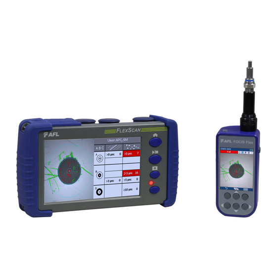
Inspecting Fibers with FOCIS Series Inspection Probe and FlexScan Optical connectors may be inspected using FOCIS Flex, FOCIS Duel, or FOCIS Lightning auto-focusing connector inspection probe with IEC pass/fail analysis . Captured fiber end-face images and pass/fail results are immediately displayed on the FOCIS probe display and on the paired FlexScan OTDR and may be saved in either FOCI or FlexScan . -
Page 28: Pairing Flexscan With Focis Flex Inspection Probe
Pairing FlexScan with FOCIS Flex Inspection Probe To transfer fiber-end images from the FOCIS Flex inspection probe and display inspection results on FlexScan, you must Bluetooth pair your FOCIS Flex probe with FlexScan . Enable Bluetooth on FlexScan From the Home screen, touch Settings . •... -
Page 29: Configuring Auto-Send
Configuring Auto-Send From the Main Menu, select Settings . • Select Capture to display the Capture settings screen . • Highlight and Select Auto-Send . • Use Arrow Keys to enable Auto-Send on 1st Capture key or on 2nd Capture key . •... -
Page 30: File Manager
File Manager Fiber test results may be stored in the FlexScan internal memory or external USB stick . Saved test results are organized into a Fiber Group sub-folder within a Project folder . The name of a saved result consists of several parameters, which are defined in the Save As screen . End 1_End 2_Cable_Fiber#_Wavelength S13 for 1310 nm Fiber Group Name... -
Page 31: Saving Results
Saving Results While in the Results view, touch Menu icon . • Touch Save As . • Edit Project, End1, End2, Cable and Fiber# names used to identify saved results: touch any field to edit it . Touch Done when finished . •... -
Page 32: Saving Results - Auto-Save & Auto-Send
Saving Results - Auto-Save & Auto-Send When a test completes, Auto-Save/Send allows users to automatically: • – Save test results to user-configured folders and file names – Optionally send test results via Bluetooth to the FlexScan App running on a mobile device Users may also manually save results or send saved results to FlexScan App by selecting the 3-bar Menu from any of the test results pages . -
Page 33: Viewing Saved Test Results
Viewing Saved Test Results To View Saved Test Results From the Home screen, touch My Projects . • Navigate through Project/Fiber Group/Fiber screens to locate the desired test record, then touch it to display test results . • – Touch up/down keys or swipe to scroll up/down through list of files . –... -
Page 34: Transferring Results To A Pc Via Usb
Transferring Results to a PC via USB To transfer files from your FlexScan to a PC using a USB cable, perform the following: Connect your FlexScan to a PC using the supplied micro-USB to USB cable . Make sure the micro-plug is fully seated in your FlexScan . •... -
Page 35: Printing Results To Pdf
Printing Results to PDF Saved test results may be organized into reports and printed to PDF file format as needed . Navigate to the desired test results and touch Menu from the results display . • Touch Print to PDF from the displayed menu . •... -
Page 36: How To View Device Information
How to View Device Information FlexScan software revision, serial number, and calibration date can be viewed from the Device Information screen, which is accessed from the Home screen . From the Home screen, touch the Menu soft key . • From the displayed sub-screen, touch Info . -
Page 37: General Information
AFL products are warranted against defective material and workmanship for a period of (1) one year from the date of delivery to the end user . Any product that is found defective within the warranty period will, at the discretion of AFL, be repaired or replaced . Warranty will be voided if the product has been repaired or altered by other than an authorized AFL product repair facility, if the void sticker has been compromised, or which have been subject to misuse, negligence, or accident . - Page 38 Test & Inspection Thank you for choosing AFL Test & Inspection! www.AFLglobal.com...
Need help?
Do you have a question about the FlexScan FS300 and is the answer not in the manual?
Questions and answers