Table of Contents
Advertisement
SELF-PROPELLED SCISSOR LIFTS
OPERATOR'S MANUAL
S06-HAE/ACE S0608-HAE/ACE S0808-HAE/ACE S0812-HAE/ACE
S1012-HAE/ACE S1212-HAE/ACE S1412-HAE/ACE
(Hydraulic Motor Drive / Electric Motor Drive)
Part Number: SM0120117A_Rev1.2
Zhejiang Dingli Machinery Co., Ltd.
with Maintenance Information
THE MANUFACTURER SHALL NOT BE HELD LIABLE IN CASE OF FAULTS
OR ACCIDENTS DUE TO NEGLIGENCE, INCAPACITY, INSTALLATION BY
UNQUALIFIED TECHNICIANS AND IMPROPER USE OF THE MACHINE
DO NOT OPERATE THIS MACHINE UNTIL YOU READ AND UNDERSTAND
ALL THE DANGERS,W ARNINGS AND CAUTIONS IN THIS MANUAL
WARNING
First Edition,
2021 Printing
July
Advertisement
Table of Contents

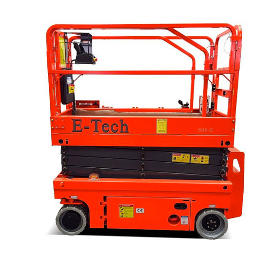
Summary of Contents for E-Tech S06-HAE
- Page 1 SELF-PROPELLED SCISSOR LIFTS OPERATOR’S MANUAL with Maintenance Information S06-HAE/ACE S0608-HAE/ACE S0808-HAE/ACE S0812-HAE/ACE S1012-HAE/ACE S1212-HAE/ACE S1412-HAE/ACE (Hydraulic Motor Drive / Electric Motor Drive) WARNING THE MANUFACTURER SHALL NOT BE HELD LIABLE IN CASE OF FAULTS OR ACCIDENTS DUE TO NEGLIGENCE, INCAPACITY, INSTALLATION BY...
- Page 2 OPERATOR’S MANUAL with Maintenance Information Version of the Record Version of the Record Version Number Create Date SM0120117A_Rev1.0 ………………………………………………………………………… 2021-03 SM0120117A_Rev1.1 ………………………………………………………………………… 2021-04 SM0120117A_Rev1.2 ………………………………………………………………………… 2021-07...
-
Page 4: Table Of Contents
OPERATOR’S MANUAL with Maintenance Information Owners, Users and operators: Important We appreciate your choice of our machine for Read, understand and obey these safety rules your application. Our number one priority is and operating instructions before operating user safety, which is best achieved by our joint this machine. -
Page 6: Safety Rules
OPERATOR’S MANUAL with Maintenance Information Safety Rules Danger Decal Legend Failure to obey the instructions and safety rules in this manual will DINGLI product decals use symbols, color coding and signal words to identify the result in death or serious injury. following: Do Not Operate Unless: Safety alert symbol —... - Page 7 Maximum capacity – S06-HAE Maximum occupants (Indoor use) Maximum occupants (Outdoor use) Platform allowable maximum load...
- Page 8 OPERATOR’S MANUAL with Maintenance Information Safety Rules Maximum occupants (Outdoor use) Platform allowable maximum load 380kg Platform allowable maximum load 380kg Extension deck allowable maximum load 113kg Maximum capacity – S0808-ACE Extension deck allowable maximum load 113kg Maximum capacity – S0808-HAE Maximum occupants (Indoor use ONLY) Maximum occupants (Indoor use ONLY) Platform allowable maximum load...
- Page 9 For outdoor use machine, do not raise the force occupants platform when wind speeds may exceed 12.5 Outdoor 200N m/s. If wind speeds exceed 12.5 m/s when the S06-HAE Indoor 400N platform is raised, lower the platform and do not continue to operate the machine. Outdoor 200N...
- Page 10 S1412-HAE/ACE). Outdoor 200N The lead-acid battery: Each battery must S1012-ACE weigh 28 kg. The batteries must weigh a Indoor 400N minimum of 112 kg. (For S06-HAE/ACE, S1212-ACE Indoor 400N S0608-HAE/ACE, S0808-HAE/ACE, S1412-ACE Indoor 400N S0812-HAE/ACE); Each battery must weigh 30 kg.
- Page 11 Maintain a firm footing on the platform floor at all times. Maximum side slope rating stowed Model Do not climb down from the platform when S06-HAE 25% (14°) 25% (14°) raised. Keep the platform floor clear of debris. S0608-HAE 25% (14°)
- Page 12 OPERATOR’S MANUAL with Maintenance Information Safety Rules charger. The lead-acid battery cannot by the lithium battery charger. Do not use the machine as a ground for welding. Explosion and Fire Hazard Be aware of crushing hazards when grasping the platform guard rail. Do not operate the machine or charge the batteries in hazardous locations where Operators must comply with employer, job site...
- Page 13 OPERATOR’S MANUAL with Maintenance Information Safety Rules The charger must match the battery. The Battery Safety lithium battery cannot by the lead-acid battery Burn Hazard charger. The lead-acid battery cannot by the lithium battery charger. Pressure relief valves are used as breathable plugs.
- Page 14 Transportation and storage Hazard The lithium battery: The battery must weigh a minimum of 50 kg. (For S06-HAE/ACE, Charge the battery as soon as receive the S0608-HAE/ACE, S0808-HAE/ACE, and machine or after long distance transportation S0812-HAE/ACE); The battery must weigh a When the battery is stored for a long time, it minimum of 62 kg.
-
Page 15: Legend
OPERATOR’S MANUAL with Maintenance Information Legend Legend 1 Platform extension 10 Lift cylinder 2 Manual storage container 11 Ground controls (on opposite side of machine) 3 Platform control 12 Entry ladder 4 Lanyard anchorage point 13 Brake release pump 5 Platform guard rails 14 Non-steer tire 6 Platform extension release pedal 15 Battery charger... -
Page 16: Decals
Decal, Warning-Charge warning 14 09410001 Decal, Danger-Explosion/burn hazard 15 09330001 Decal, Danger-Safety arm 09640109 Decal, Label-S06-ACE (S06-ACE) 09640110 Decal, Label-S06-HAE (S06-HAE) Decal, Caution-Max. manual force 400N (Indoor) 17 09440009 200N (Outdoor) 09940003 Decal, Label-E-Tech (S06-ACE) 09940004 Decal, Label-Summit (S06-HAE) 19 09410005... - Page 17 OPERATOR’S MANUAL with Maintenance Information Decals S06-HAE/ACE Safety tape...
- Page 18 OPERATOR’S MANUAL with Maintenance Information Decals S06-HAE/ACE...
- Page 19 OPERATOR’S MANUAL with Maintenance Information Decals S0608-HAE/ACE~ S1412-HAE/ACE Part No. Description Qty. Remark 09440011 Decal, Label-Lanyard anchorage point 09340001 Decal, Notice-Keep the manual with the machine 09440001 Decal, Danger-General safety rules 09440003 Decal, Danger-Tip-over hazard, tilt-alarm Decal, Instructions-Refer the operator to the 09340003 instructions for use 09440013...
- Page 20 09440009 Indoor200N Outdoor S1012-HAE/ACE S0808-HAE/ACE, S0812-HAE/ACE, 09440007 Decal, Caution-Max. manual force 400N S1212-HAE/ACE, S1412-HAE/ACE S0608-ACE,S0808-ACE, 09940003 Decal, Label-E-Tech S0812-ACE,S1012-ACE, S1212-ACE,S1412-ACE S0608-HAE,S0808-HAE 09940004 Decal, Label-Summit S0812-HAE,S1012-HAE S1212-HAE,S1412-HAE 20 09410005 Decal, Danger-Do not alter or disable limit switch 21 09310004 Decal, Instructions-Emergency lower...
- Page 21 OPERATOR’S MANUAL with Maintenance Information Decals Safety tape S0608-HAE/ACE~ S1412-HAE/ACE...
- Page 22 OPERATOR’S MANUAL with Maintenance Information Decals S0608-HAE/ACE~ S1412-HAE/ACE...
- Page 23 OPERATOR’S MANUAL with Maintenance Information Decals...
-
Page 24: Specifications
OPERATOR’S MANUAL with Maintenance Information Specifications Model: S06-HAE Height, working maximum 7.8 m Maximum hydraulic pressure 180 bar (functions) Height, platform maximum 5.8 m System voltage 24 V Height, stowed maximum 2.01 m Rails up Tire size Φ323×100 mm Height, stowed maximum 1.83 m... - Page 25 OPERATOR’S MANUAL with Maintenance Information Specifications Model: S0608-HAE Maximum hydraulic pressure 240 bar Height, working maximum (functions) Height, platform maximum System voltage 24 V Height, stowed maximum 2.23 m Tire size Φ381×127 mm Rails up Airborne noise emissions <70 dB Height, stowed maximum 1.87 m Rails folded...
- Page 26 OPERATOR’S MANUAL with Maintenance Information Specifications Model: S0808-HAE Maximum hydraulic pressure 240 bar Height, working maximum 10 m (functions) Height, platform maximum System voltage 24 V Height, stowed maximum 2.36 m Tire size Φ381×127 mm Rails up Airborne noise emissions <70 dB Height, stowed maximum 2.00 m...
- Page 27 OPERATOR’S MANUAL with Maintenance Information Specifications Model: S0812-HAE Maximum hydraulic pressure 240 bar Height, working maximum 10 m (functions) Height, platform maximum System voltage 24 V Height, stowed maximum 2.36 m Tire size Φ381×127 mm Rails up Airborne noise emissions <70 dB Height, stowed maximum 1.83 m...
- Page 28 OPERATOR’S MANUAL with Maintenance Information Specifications Model: S1012-HAE Maximum hydraulic pressure 240 bar Height, working maximum 12 m (functions) Height, platform maximum 10 m System voltage 24 V Height, stowed maximum 2.49 m Tire size Φ381×127 mm Rails up Airborne noise emissions <70 dB Height, stowed maximum 1.96 m...
- Page 29 OPERATOR’S MANUAL with Maintenance Information Specifications Model: S1212-HAE Maximum hydraulic pressure 240 bar Height, working maximum 13.8 m (functions) Height, platform maximum 11.8 m System voltage 24 V Height, stowed maximum 2.62 m Tire size Φ381×127 mm Rails up Airborne noise emissions <70 dB Height, stowed maximum 2.09 m...
- Page 30 OPERATOR’S MANUAL with Maintenance Information Specifications Model: S1412-HAE Maximum hydraulic pressure 240 bar Height, working maximum 15.7 m (functions) Height, platform maximum 13.7 m System voltage 24 V Height, stowed maximum 2.62 m Tire size Φ381×127 mm Rails up Airborne noise emissions <70 dB Height, stowed maximum 2.09 m...
- Page 31 OPERATOR’S MANUAL with Maintenance Information Specifications Model: S06-ACE Height, working maximum 7.8 m Maximum hydraulic pressure 180bar (functions) Height, platform maximum 5.8 m System voltage 24 V Height, stowed maximum 2.01 m Rails up Tire size Φ323×100 mm Height, stowed maximum 1.83 m Airborne noise emissions <70 dB...
- Page 32 OPERATOR’S MANUAL with Maintenance Information Specifications Model: S0608-ACE Maximum hydraulic pressure 240 bar Height, working maximum (functions) Height, platform maximum System voltage 24 V Height, stowed maximum 2.23 m Tire size Φ381×127 mm Rails up Airborne noise emissions <70 dB Height, stowed maximum 1.87 m Rails folded...
- Page 33 OPERATOR’S MANUAL with Maintenance Information Specifications Model: S0808-ACE Maximum hydraulic pressure 240 bar Height, working maximum 10 m (functions) Height, platform maximum System voltage 24 V Height, stowed maximum 2.36 m Tire size Φ381×127 mm Rails up Airborne noise emissions <70 dB Height, stowed maximum 2.00 m...
- Page 34 OPERATOR’S MANUAL with Maintenance Information Specifications Model: S0812-ACE Maximum hydraulic pressure 240 bar Height, working maximum 10 m (functions) Height, platform maximum System voltage 24 V Height, stowed maximum 2.36 m Tire size Φ381×127 mm Rails up Airborne noise emissions <70 dB Height, stowed maximum 1.83 m...
- Page 35 OPERATOR’S MANUAL with Maintenance Information Specifications Model: S1012-ACE Maximum hydraulic pressure 240 bar Height, working maximum 12 m (functions) Height, platform maximum 10 m System voltage 24 V Height, stowed maximum 2.49 m Tire size Φ381×127 mm Rails up Airborne noise emissions <70 dB Height, stowed maximum 1.96 m...
- Page 36 OPERATOR’S MANUAL with Maintenance Information Specifications Model: S1212-ACE Maximum hydraulic pressure 240 bar Height, working maximum 13.8 m (functions) Height, platform maximum 11.8 m System voltage 24 V Height, stowed maximum 2.62 m Tire size Φ381×127 mm Rails up Airborne noise emissions <70 dB Height, stowed maximum 2.09 m...
- Page 37 OPERATOR’S MANUAL with Maintenance Information Specifications Model: S1412-ACE Maximum hydraulic pressure 240 bar Height, working maximum 15.7 m (functions) Height, platform maximum 13.7 m System voltage 24 V Height, stowed maximum 2.62 m Tire size Φ381×127 mm Rails up Airborne noise emissions <70 dB Height, stowed maximum 2.09 m...
- Page 38 OPERATOR’S MANUAL with Maintenance Information Specifications Battery Specifications Lead-acid battery S1012-ACE, S1012-HAE optional S06-ACE, S06-HAE, standard S0608-ACE, S0608-HAE, Voltage 6VDC S0808-ACE, S0808-HAE, Type T-125 Plus S0812-ACE, S0812-HAE Quantity Voltage 6VDC Battery capacity, maximum 240Ah Type 6TB170 Maintenance-free Quantity S1212-ACE, S1212-HAE,...
- Page 39 OPERATOR’S MANUAL with Maintenance Information Specifications Lithium battery S06-ACE, S06-HAE, optional S0608-ACE, S0608-HAE, S0808-ACE, S0808-HAE, S0812-ACE, S0812-HAE Voltage 24VDC Type TFL24-180-DL3 Quantity Battery capacity, maximum 180AH Maintenance-free S1012-ACE, S1012-HAE, optional S1212-ACE, S1212-HAE, S1412-ACE, S1412-HAE Voltage 24VDC Type TFL24-220-DL2 Quantity Battery capacity, maximum...
-
Page 40: Control Panel
OPERATOR’S MANUAL with Maintenance Information Control Panel Ground Control Panel 1 Menu escape button 9 Platform up button 10 Red Emergency Stop button 2 LED readout screen Push in the red Emergency Stop button to 3 Menu up button the off position to stop all functions. Pull out the red Emergency Stop button to the 4 Menu down button on position to operate the machine. - Page 41 OPERATOR’S MANUAL with Maintenance Information Control Panel Platform Control Panel Function enable switch Drive function select button Thumb rocker switch Drive speed button Proportional control handle 8 LED readout screen Horn button 9 Red Emergency Stop button Lift function select button...
- Page 42 OPERATOR’S MANUAL with Maintenance Information Control Panel Platform Control Panel Horn Button Function enable switch Push the horn button and the horn will Press and hold the function enable switch sound. Release the horn button and the to enable the drive/lift function. horn will stop.
-
Page 43: Pre-Operation Inspection
OPERATOR’S MANUAL with Maintenance Information Pre-operation Inspection Do Not Operate Unless: Fundamentals It is the responsibility of the operator to √ You learn and practice the principles of perform a pre-operation inspection and routine safe machine operation contained in this maintenance. - Page 44 OPERATOR’S MANUAL with Maintenance Information Pre-operation Inspection Pre-operation Inspection Check entire machine for: Be sure that the operator’s manual are complete, legible and in the storage Cracks in welds or structural container located in the platform. components Be sure that all decals are legible and in ...
-
Page 45: Workplace Inspection
OPERATOR’S MANUAL with Maintenance Information Workplace Inspection Fundamentals Do Not Operate Unless: The workplace inspection helps the operator √ You learn and practice the principles of determine if the workplace is suitable for safe safe machine operation contained in this machine operation. -
Page 46: Function Tests
OPERATOR’S MANUAL with Maintenance Information Function Tests Fundamentals Do Not Operate Unless: The function tests are designed to discover √ You learn and practice the principles of any malfunctions before the machine is put safe machine operation contained in this into service. - Page 47 OPERATOR’S MANUAL with Maintenance Information Function Tests Select a test area that is firm, level and 11 Press the platform up or platform down free of obstruction. button. Be sure the battery pack is connected. ⊙ Result: No function should operate. Pull out the main power switch to “on”...
- Page 48 OPERATOR’S MANUAL with Maintenance Information Function Tests At the Platform Controls descent alarm should sound while the platform is lowering. Test Emergency Stop Test the Steering 20 Push in the platform red Emergency Stop Note: When performing the steer and drive button to the off position.
- Page 49 OPERATOR’S MANUAL with Maintenance Information Function Tests 38 Slowly move the control handle in the The platform controls LED readout should direction indicated by the yellow down display LL. arrow on the control panel until the 45 Press the drive function select button. machine begins to move, then return the 46 Press and hold the function enable switch handle to the center position.
- Page 50 OPERATOR’S MANUAL with Maintenance Information Function Tests screen readout should display 18. 53 Press the drive function select button. 54 Press and hold the function enable switch on the control handle. 55 Move the control handle in the direction indicated by the blue up arrow, and then move the control handle in the direction indicated by the yellow down arrow.
- Page 51 OPERATOR’S MANUAL with Maintenance Information Function Tests 62 Try to raise the platform. ⊙ Result: The platform will continue to raise, the alarm should continue to beeps 110 ⊙ Result: The platform can be raised the times per minute, and the platform LED alarm should beep 50 times per minute and display shows "0b".(Obstacle) continue, the platform LED display shows...
-
Page 52: Operating Instructions
OPERATOR’S MANUAL with Maintenance Information Operating Instructions Do Not Operate Unless: The Operating Instructions section provides instructions for each aspect of machine √ You learn and practice the principles of operation. safe machine operation contained in this It is the operator's responsibility to follow all operator's manual. - Page 53 OPERATOR’S MANUAL with Maintenance Information Operating Instructions Emergency Stop To Steer Press the drive function select button. Push in the red Emergency Stop button to the off position at the ground controls or the Press and hold the function enable switch platform controls to stop all machine functions.
- Page 54 OPERATOR’S MANUAL with Maintenance Information Operating Instructions Maximum slope rating, stowed position 25%, Be aware of the direction the machine will maximum side slope rating, stowed position travel when using the controller. 25%. Note: Slope rating is subject to ground Battery Level Indicator conditions and adequate traction.
- Page 55 OPERATOR’S MANUAL with Maintenance Information Operating Instructions platform extension. Fully lower the platform and retract the platform extension. Remove the platform controls. Remove the platform controls. From inside the platform, remove the two front extension deck wire lock pins. From inside the platform, remove the two front extension deck wire lock pins.
- Page 56 OPERATOR’S MANUAL with Maintenance Information Operating Instructions extension deck by foot. ultrasonic sensor and the wiring harness connected to the platform control to relieve the Push the platform extension guardrail to limit. extend the platform to the desired position. Do not stand on the platform extension while trying to extend it.
- Page 57 OPERATOR’S MANUAL with Maintenance Information Operating Instructions Error indicator readout The LED readout screen displays fault codes that provide information about the machine operating status and about malfunctions. The fault codes listed in the following charts describe malfunctions and can aid in troubleshooting the machine by pinpointing the area or component affected.
- Page 58 OPERATOR’S MANUAL with Maintenance Information Operating Instructions Display Description Lift Reaction 56 Steer Right Coil Fault Disable Lifting and Driving 57 Steer Left Coil Fault Disable Lifting and Driving 59 Parallel Coil Fault Disable Lifting and Driving Battery Low Voltage Disables All Motion Platform Load is over 80% Warning Only...
- Page 59 OPERATOR’S MANUAL with Maintenance Information Operating Instructions Display Description Lift Reaction 1018, 2018, 3018 LOGIC FAILURE #2 Controller Dependent 1019, 2019, 3019 LOGIC FAILURE #1 Controller Dependent 1028, 2028, 3028 PUMP VMN LOW Controller Dependent 1029, 2029, 3029 PUMP VMN HIGH Controller Dependent 1030, 2030, 3030 VMN LOW...
- Page 60 OPERATOR’S MANUAL with Maintenance Information Operating Instructions Display Description Lift Reaction 1160, 2160, 3160 SENS BAT TEMP KO Controller Dependent 1161, 2161, 3161 RPM HIGH Controller Dependent 1162, 2162, 3162 BUMPER STOP Controller Dependent 1163, 2163, 3163 ED SLIP MISMATCH Controller Dependent 1164, 2164, 3164 PWM ACQ.
- Page 61 OPERATOR’S MANUAL with Maintenance Information Operating Instructions Display Description Lift Reaction 1193, 2193, 3193 SMARTDRIVER KO Controller Dependent 1194, 2194, 3194 AUX BATT. SHORT. Controller Dependent 1195, 2195, 3195 POS. EB. SHORTED Controller Dependent 1196, 2196, 3196 MOT.PHASE SH. Controller Dependent 1197, 2197, 3197 WRONG SLAVE VER.
- Page 62 OPERATOR’S MANUAL with Maintenance Information Operating Instructions Display Description Lift Reaction 1223, 2223, 3223 COIL SHOR.MC Controller Dependent 1224, 2224, 3224 WAITING FOR NODE Controller Dependent 1224, 2224, 3224 WAITING FOR NODE Controller Dependent 1224, 2224, 3224 WAITING FOR NODE Controller Dependent 1226, 2226, 3226 VACC OUT RANGE...
- Page 63 OPERATOR’S MANUAL with Maintenance Information Operating Instructions Display Description Lift Reaction 1249, 2249, 3249 CHECK UP NEEDED Controller Dependent 1250, 2250, 3250 THERMIC SENS. KO Controller Dependent 1251, 2251, 3251 WRONG SET BAT. Controller Dependent 1253, 2253, 3253 FIELD ORIENT. KO Controller Dependent 1254, 2254, 3254 EB.
- Page 64 OPERATOR’S MANUAL with Maintenance Information Operating Instructions Display Description Lift Reaction 4020 Discharge total voltage low 3 Disables All Motion 4021 Charge total voltage high 2 Lift and Drive speed limit 4022 Charge total voltage high 3 Disables All Motion 4023 High charge current 2 Lift and Drive speed limit...
- Page 65 OPERATOR’S MANUAL with Maintenance Information Operating Instructions Battery and Charger Instructions To Charge Battery Be sure the batteries are connected before Observe and Obey: charging. √ Do not use an external charger or booster Open the battery compartment. The battery. compartment should remain open for the entire charging cycle.
- Page 66 OPERATOR’S MANUAL with Maintenance Information Operating Instructions pack should be in good contact. If discharged state. This also applies to batteries something goes wrong, it needs to be fixed in a state of deep discharge. Otherwise, the before it can be charged. service life of the battery will be significantly reduced.
-
Page 67: Transport And Lifting Instructions
OPERATOR’S MANUAL with Maintenance Information Transport and Lifting Instructions Observe and Obey: Brake Release Operation For the Hydraulic Motor Drive Model √ Common sense and planning must be applied to control the movement of the Chock the wheels to prevent the machine machine when lifting it with a crane or from rolling. - Page 68 OPERATOR’S MANUAL with Maintenance Information Transport and Lifting Instructions released!" Release all brakes Securing to Truck or Trailer for Transit If you want to close the brake release, just turn off the key switch in “ground” position. Always chock the machine wheels in Towing the Hydraulic Drive Model is not preparation for transport.
- Page 69 OPERATOR’S MANUAL with Maintenance Information Transport and Lifting Instructions Lifting the Machine with a Observe and Obey: Forklift √ Only qualified riggers should rig and lift the machine. Be sure the extension deck, controls and component trays are secure. Remove all loose √...
- Page 70 Fully lower the platform. Be sure the extension Model X Axis Y Axis decks, controls and covers are secure. Remove all loose items on the machine. S06-HAE 60 cm 59.1cm S06-ACE Determine the center of gravity of your machine using the table and the picture on this S0608-HAE 90.5 cm...
-
Page 71: Storage
OPERATOR’S MANUAL with Maintenance Information Storage How to store the batteries Observe and Obey: When storing the machine for a long time √ The storage of the machine shall be as (one month to six months) be sure to turn follows, Incorrect storage may affect the off the main power switch, key switch and performance and service life of the machine... - Page 72 OPERATOR’S MANUAL with Maintenance Information Storage negative pole of the battery should be removed and the lithium battery should be charged regularly once a month Lithium batteries should be stored in a dry, frost-free room. Avoid contact between lithium batteries and corrosive objects, and keep away from places with fire sources and heat sources.
-
Page 73: Maintenance
OPERATOR’S MANUAL with Maintenance Information Maintenance Pre-delivery Preparation Report Observe and Obey: The pre-delivery preparation report contains √ Only routine maintenance items specified in checklists for each type of scheduled this manual shall be performed by the inspection. operator. Make copies of the Pre-delivery Preparation √... - Page 74 OPERATOR’S MANUAL with Maintenance Information Maintenance Pre-delivery Preparation Report Fundamentals Instructions It is the responsibility of the dealer to perform Use the operator’s manual on your machine. the Pre-delivery Preparation. The Pre-delivery Preparation consists of The Pre-delivery Preparation is performed completing the Pre-operation Inspection, the prior to each delivery.
- Page 75 OPERATOR’S MANUAL with Maintenance Information Maintenance Maintenance Inspection Report Checklist A Y N R Model A-1 Inspect the manuals and decals Serial number A-2 Pre-operation inspection Date A-3 Check the Batteries Hour meter A-4 Check the Hydraulic Oil Level Machine owner A-5 Function tests Inspected by (print) Perform after 40 hours:...
- Page 76 OPERATOR’S MANUAL with Maintenance Information Maintenance Checklist A Procedures Inspect the Manuals and Decals Maintaining the operator’s manual in good ⊙ Result: The machine is equipped with all condition is essential to safe machine required decals, and all decals are legible operation.
- Page 77 OPERATOR’S MANUAL with Maintenance Information Maintenance Perform Pre-operation Inspection Check the Batteries Completing a Pre-operation Inspection is essential to safe machine operation. The Pre-operation Inspection is a visual inspection Proper battery condition is essential to good performed by the operator prior to each work machine performance and operational safety.
- Page 78 ⊙ Result: The hydraulic oil level should be at the mark of the fuel tank. (Refer to the following table). Scale line(L) Model S06-HAE/ACE S0608-HAE/ACE Perform 30 Day Service S0808-HAE/ACE S0812-HAE/ACE S1012-HAE/ACE 17.5...
- Page 79 OPERATOR’S MANUAL with Maintenance Information Maintenance Checklist B Procedures Inspect the Batteries Models without maintenance-free or sealed DINGLI requires that this procedure be batteries: performed every 250 hours or quarterly, whichever comes first. Remove the battery vent caps and check the specific gravity of each battery cell with Proper battery condition is essential to good a hydrometer.
- Page 80 OPERATOR’S MANUAL with Maintenance Information Maintenance fully charged. Proceed to step 11. ¤ Result: The difference in specific gravity readings between cells is greater than 0.1 OR the specific gravity of one or more cells is less than 1.177. Replace the battery. 11 Check the battery acid level.
- Page 81 OPERATOR’S MANUAL with Maintenance Information Maintenance All models: 18 Check each battery pack and verify that Inspect the Electrical Wiring the batteries are wired correctly. 19 Inspect the battery charger plug and pigtail for damage or excessive insulation wear. DINGLI requires that this procedure be Replace as required.
- Page 82 OPERATOR’S MANUAL with Maintenance Information Maintenance Lift the upper safety arm, move it to the center of the scissor arm and rotate down Inspect the Tires and Wheels to a vertical position. (for S1212-HAE/ACE, (including castle nut torque) S1412-HAE/ACE). Lower the platform until the safety arm rests securely on the link.
- Page 83 OPERATOR’S MANUAL with Maintenance Information Maintenance Test the Emergency Stop Test the Key Switch DINGLI requires that this procedure be DINGLI requires that this procedure be performed every 250 hours or quarterly, performed every 250 hours or quarterly, whichever comes first. whichever comes first.
- Page 84 OPERATOR’S MANUAL with Maintenance Information Maintenance Test the Automotive-style Horn (if Test the Drive Brakes equipped) DINGLI requires that this procedure be DINGLI requires that this procedure be performed every 250 hours or quarterly, performed every 250 hours or quarterly, whichever comes first.
- Page 85 OPERATOR’S MANUAL with Maintenance Information Maintenance ¤ Result: The machine does not stop within the specified braking distance. Test the Drive Speed - Stowed Note: The brakes must be able to hold the Position machine on any slope it is able to climb. Replace the brakes and repeat this procedure beginning with step 1.
- Page 86 OPERATOR’S MANUAL with Maintenance Information Maintenance B-10 Test the Drive Speed - Raised Test the Slow Drive Speed Position DINGLI requires that this procedure be performed every 250 hours or quarterly, DINGLI requires that this procedure be whichever comes first. performed every 250 hours or quarterly, whichever comes first.
- Page 87 OPERATOR’S MANUAL with Maintenance Information Maintenance B-11 B-12 Perform Hydraulic Oil Analysis Inspect the Hydraulic Tank Cap Venting System DINGLI requires that this procedure be performed every 250 hours or quarterly, DINGLI requires that this procedure be whichever comes first. performed quarterly or every 250 hours, whichever comes first.
- Page 88 OPERATOR’S MANUAL with Maintenance Information Maintenance B-13 B-14 Check the Module Tray Latch Test the Pothole Limit Switches and Components the Level Sensor DINGLI requires that this procedure be DINGLI requires that this procedure be performed every 250 hours or quarterly, performed every 250 hours or quarterly, whichever comes first.
- Page 89 OPERATOR’S MANUAL with Maintenance Information Maintenance deployed. Adjust or replace the level machine is functioning properly. sensor. ¤ Result: The LED readout screen does not Press the drive function select button. show code 18, the alarm does not sound Standing on the up-hill side of the machine, and the steer and drive functions operate.
- Page 90 OPERATOR’S MANUAL with Maintenance Information Maintenance Checklist C Procedures Test the Platform Overload System (if equipped) Perform this procedure with DINGLI requires that this procedure be the machine on a firm, level surface. performed every 500 hours or six months, whichever comes first or when the machine Turn the key switch to platform controls.
- Page 91 OPERATOR’S MANUAL with Maintenance Information Maintenance Turn the key switch to ground control. Test all machine functions from the ground Replace the Hydraulic Tank Breather controls ⊙ Result: All ground control functions should not operate. Lift the test weight off the platform floor DINGLI requires that this procedure be using a suitable lifting device.
- Page 92 Perform this procedure with the platform in the end of the machine. stowed position. For S06-HAE/ACE: Measure the distance between the number one arm cross tube and the chassis deck ⊙ Result: The measurement is 23mm or more.
- Page 93 OPERATOR’S MANUAL with Maintenance Information Maintenance Replace the Hydraulic Tank Return Filter Element DINGLI requires that this procedure be performed every 1000 hours or annually, whichever comes first. Replacement of the hydraulic tank return filter is essential for good machine performance and service life.
- Page 94 OPERATOR’S MANUAL with Maintenance Information Maintenance Checklist E Procedure Test or Replace the Hydraulic Oil Tag and disconnect the hydraulic pump DINGLI requires that this procedure be inlet line and remove the line from the tank. performed every 2000 hours or every two Cap the fitting on the pump.
- Page 95 OPERATOR’S MANUAL with Maintenance Information Maintenance 13 Install the hydraulic pump inlet line into the tank. Install the fitting onto the pump and torque. 14 Install the hydraulic pump return line into the tank. Install the fitting onto the hydraulic filter head and torque. 15 Fill the tank with hydraulic oil until the fluid is full in the hydraulic tank.
-
Page 96: Schematic
OPERATOR’S MANUAL with Maintenance Information Schematic Hydraulic Schematic S06-HAE... - Page 97 OPERATOR’S MANUAL with Maintenance Information Schematic Hydraulic Schematic S0608-HAE S0808-HAE S0812-HAE...
- Page 98 OPERATOR’S MANUAL with Maintenance Information Schematic Hydraulic Schematic S1012-HAE S1212-HAE S1412-HAE...
- Page 99 OPERATOR’S MANUAL with Maintenance Information Schematic Hydraulic Schematic S06-ACE Platform loading (Option) Sensor Steer cylinder Lift cylinder Lower valve 80bar 150bar Function valve Pump Filter Filter Tank...
- Page 100 OPERATOR’S MANUAL with Maintenance Information Schematic Hydraulic Schematic S0608-ACE S0808-ACE S0812-ACE Platform loading (Option) Sensor Steer cylinder Lift cylinder Lower valve 120bar RV1=130bar(JCPT0808AC) (S0608-ACE) RV1=160bar(JCPT1008AC) (S0808-ACE) RV1=210bar(JCPT1012AC) (S0812-ACE) Function valve Pump Filter Filter Tank...
- Page 101 OPERATOR’S MANUAL with Maintenance Information Schematic Hydraulic Schematic S1012-ACE S1212-ACE S1412-ACE Platform loading (Option) Sensor Steer cylinder Lower lift Upper lift cylinder cylinder Lower valve Lower valve 120bar RV1=150bar(S1012-ACE) RV1=150bar(JCPT1212AC) RV1=190bar(S1212-ACE) RV1=190bar(JCPT1412AC) RV1=200bar(JCPT1612AC) RV1=200bar(S1412-ACE) RV1=210bar(JCPT1612ACS) Function valve Pump Filter Filter Tank...
- Page 102 OPERATOR’S MANUAL with Maintenance Information Schematic Electrical Schematic S06-HAE (Lead-acid battery)
- Page 103 OPERATOR’S MANUAL with Maintenance Information Schematic Electrical Schematic S0608-HAE~S1412-HAE (Lead-acid battery)
- Page 104 OPERATOR’S MANUAL with Maintenance Information Schematic Electrical Schematic S06-HAE (Lithium battery)
- Page 105 OPERATOR’S MANUAL with Maintenance Information Schematic Electrical Schematic S0608-HAE~S1412-HAE (Lithium battery)
- Page 106 OPERATOR’S MANUAL with Maintenance Information Schematic Electrical Schematic S06-ACE (Lead-acid battery)
- Page 107 OPERATOR’S MANUAL with Maintenance Information Schematic Electrical Schematic S0608-ACE~S1412-ACE (Lead-acid battery)
- Page 108 OPERATOR’S MANUAL with Maintenance Information Schematic Electrical Schematic S06-ACE (Lithium battery)
- Page 109 OPERATOR’S MANUAL with Maintenance Information Schematic Electrical Schematic S0608-ACE~S1412-ACE (Lithium battery)
-
Page 110: Inspection And Repair Log
OPERATOR’S MANUAL with Maintenance Information Schematic Inspection and Repair Log Date Comments...
Need help?
Do you have a question about the S06-HAE and is the answer not in the manual?
Questions and answers