
Related Manuals for Room essentials 430238


Summary of Contents for Room essentials 430238
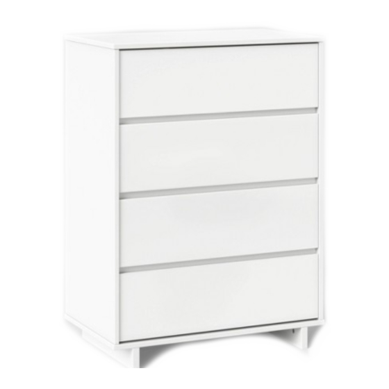
- Page 1 4-drawer chest style # 430238 (white) dpci # 249 - 05 - 0003 >> assembly instructions...
-
Page 2: Before You Begin
1. Check for damaged or missing parts. Visit www.sauder.com/services to order missing supplies. 2. Use the carton as a working surface to prevent product damage during assembly. 3. Gather all tools prior to assembly. tools needed tip shown actual size 430238... - Page 3 United States and Canada (except holidays) replacement parts, please visit our web site. Consumer Services 1-800-523-3987 Lot #: 560425 Most replacement parts ship from our facility in one or two business days. Date Purchased:______________ 02 / 04 / 21 430238...
-
Page 4: Part List
4 (1 with label) D182 drawer back D988 drawer bottom bottom side skirt skirt upper drawer front D182 lower drawer front lower back D988 upper back drawer brace (Hidden part using recycled material. Color may vary.) D182 D988 430238... - Page 5 Using a screw that is too long will cause damage. Before beginning assembly, separate each type of screw. Carefully study the screw diagrams (SHOWN ACTUAL SIZE). Pay close attention to the color of each screw. You may receive extra hardware with your unit. 430238...
- Page 6 Assemble your unit on a carpeted fl oor or on the empty carton to avoid scratching your unit or the fl oor. Fasten the UNIVERSAL CABINET RAILS* (35AA) to the ENDS (A and B). Use sixteen GOLD 5/16" FLAT HEAD SCREWS (3S) through holes #1 and #3. *patent pending glide system 430238...
- Page 7 (2F) x 8 hidden cam cam dowel Arrow Metal end Push eight HIDDEN CAMS (1F) into the ENDS (A and B) and LOWER BACK (K). Then, insert the metal end of a CAM DOWEL (2F) into each HIDDEN CAM. 430238...
- Page 8 To completely tighten: Start Tighten r f a Maximum Arrow h o u Arrow 210 degrees w i t Minimum H I D 190 degrees Fasten the ENDS (A and B) to the LOWER BACK (K). Tighten four HIDDEN CAMS. 430238...
- Page 9 Insert twelve WOOD DOWELS (15F) into the BRACES (D). Insert the WOOD DOWELS in the BRACES (D) into the ENDS (A and B). NOTE: You will need to gently fl ex the ENDS out slightly to insert the WOOD DOWELS into the holes in the ENDS. 430238...
- Page 10 Open the FURNITURE TIPPING RESTRAINT KIT (97), and fasten the SAFETY STRAP to the TOP (C). Use the short screw provided. NOTE: Position the SAFETY STRAP exactly as shown. Fasten the TOP (C) to the ENDS (A and B). Tighten four HIDDEN CAMS. 430238...
- Page 11 Push six HIDDEN CAMS (1F) into the SKIRTS (F and G). Then, insert the metal end of a CAM DOWEL (2F) into each HIDDEN CAM. Fasten two METAL BRACKETS (4G) to the SKIRT (G) exactly as shown. Use two BLACK 9/16" LARGE HEAD SCREWS (1S). NOTE: Be sure the BRACKETS are even with the edge of the SKIRT. 430238...
- Page 12 Fasten the SIDE SKIRTS (F) to the SKIRT (G). Tighten two HIDDEN CAMS. Fasten the SIDE SKIRTS (F) to the BOTTOM (E). Tighten four HIDDEN CAMS. Fasten the BRACKETS on the SKIRT (G) to the BOTTOM (E). Use two BLACK 9/16" LARGE HEAD SCREWS (1S). 430238...
- Page 13 Fasten the BOTTOM (E) to the ENDS (A and B). Use four BLACK 1-15/16" FLAT HEAD SCREWS (113S). NOTE: You should start each SCREW a few turns before completely tightening any of them. NOTE: Be sure the WOOD DOWELS in the ENDS insert into the BOTTOM. 430238...
-
Page 14: Safety Strap
Fasten the bottom edge of the UPPER BACK (L) to the LOWER BACK (K). Use eight BLACK 9/16" LARGE HEAD SCREWS (1S). Fasten the UPPER BACK (L) to the ENDS (A and B) and TOP (C) using the NAILS (1N). 430238... -
Page 15: Installation Instructions
4. Turn the screw until it is fl ush against the wall and you feel a fi rm resistance. 5. Continue to turn until the screw starts spinning freely. NOTE: Before moving your unit to a diff erent location, unscrew the SAFETY DRYWALL ANCHOR from your wall. The nylon sheath will remain behind your wall. 430238... -
Page 16: Drawer Bottom
Fasten the DRAWER FRONT BRACKETS (8G) to the UPPER DRAWER FRONT (H). Use four BLACK 9/16" LARGE HEAD SCREWS (1S). Slide a DRAWER BOTTOM (D988) into the grooves in the DRAWER SIDES (D44 and D45) and UPPER DRAWER FRONT (H). 430238... -
Page 17: Hidden Cam
Fasten a DRAWER BACK (D182) to the DRAWER SIDES (D44 and D45) and DRAWER BRACE (M67). Use fi ve BLACK 1-9/16" FLAT HEAD SCREWS (30S). NOTE: You should start each SCREW a few turns before completely tightening any of them. Repeat Steps 11-12 for the lower drawers. The angled edge of the lower drawer front will be opposite from the upper drawer front. 430238... - Page 18 Fasten a DRAWER RIGHT (35AC) to the RIGHT DRAWER SIDE (D44) and a DRAWER LEFT (35AD) to the LEFT DRAWER SIDE (D45). Use four GOLD 5/16" FLAT HEAD SCREWS (3S) through holes #1 and #2. NOTE: The glides are not intended to rotate. Repeat this step for the other drawers. 430238...
- Page 19 To insert the drawer into your unit, tip the front of the drawer down and drop the glides on the drawer behind the glides on the unit. Lift the front of the drawer up and slide it into the unit. 430238...
- Page 20 Tighten the SCREW. Adjust the drawer up or down. Open the drawer. Loosen these SCREWS. Adjust the DRAWER FRONT up or down as needed. Tighten the SCREWS. If further adjustments are needed, go to diagram 2. 430238...
- Page 21 • NE at a time t item vies • Pla 526119 1/19 25 lbs. each NOTE: Please read the back pages of the instruction booklet for important safety information. This completes assembly. Clean with a damp cloth. Wipe dry. 430238...
-
Page 22: Year Limited Warranty
6. For Warranty inquiries or claims, please visit our website www.sauder.com. You can also contact Sauder at 1.800.523.3987. Sauder may require Warranty claims to be submitted in writing to: Sauder Woodworking Co., 502 Middle Street, Archbold, OH 43502 USA. Please include your sales receipt or other proof of purchase and a specifi c description of the product defect. 430238... - Page 23 Moving furniture that is not designed to be moved or equipped with casters may result in injury or damage to furnishings or personal property. ALWAYS unload shelves and drawers, starting with the top surfaces, before moving. NEVER push or pull furniture on carpet. Have a friend help lift properly to move and/or reposition it. Date of Manufacture: ________________ 430238...
-
Page 25: Instrucciones De Montaje
4 cajones estilo n.º 430238 (blanco) dpci n.º 249 - 05 - 0003 >> instrucciones de montaje... -
Page 26: Antes De Comenzar
1. Compruebe si faltan piezas o están dañadas. Visite www.sauder.com/services para pedir las piezas que falten. 2. Use la caja como superfi cie de trabajo para evitar dañar el producto durante el montaje. 3. Reúna todas las herramientas necesarias antes de comenzar el montaje. herramientas necesarias punta a tamaño real 430238... - Page 27 La mayoría de las piezas de repuesto se envían desde nuestra Lote n.º: 560425 instalación en uno o dos días hábiles. Fecha de compra:______________ 02 / 04 / 21 430238...
-
Page 28: Lista De Piezas
D988 fondo del cajón fondo falda lateral falda frente del cajón superior D182 frente del cajón inferior parte trasera inferior D988 parte trasera superior soporte del cajón (Pieza oculta hecha con material reciclado. El color puede variar.) D182 D988 430238... -
Page 29: Accesorios De Instalación
Usar un tornillo demasiado largo causará daños. Antes de comenzar el ensamblaje, separe cada tipo de tornillo. Estudie con detenimiento los diagramas de los tornillos (SE MUESTRAN EN TAMAÑO REAL). Preste mucha atención al color de cada tornillo. Puede recibir accesorios de instalación adicionales con su unidad. 430238... - Page 30 Ensamble la unidad sobre un piso con alfombra o sobre el cartón vacío para evitar rayar la unidad o el piso. Sujete los RIELES UNIVERSALES DE GABINETE* (35AA) a los EXTREMOS (A y B). Utilice dieciséis TORNILLOS DORADOS DE CABEZA PLANA DE 5/16" (3S) en los orifi cios 1 y 3. *sistema de deslizamiento de patente pendiente 430238...
- Page 31 Empuje ocho ROSCAS DE SUJECIÓN OCULTAS (1F) en los EXTREMOS (A y B) y la PARTE TRASERA INFERIOR (K). A continuación, inserte el extremo de metal de un PASADOR DE MONTAJE DE ROSCA DE SUJECIÓN (2F) en cada ROSCA DE SUJECIÓN OCULTA. 430238...
- Page 32 Máximo 210 Flecha Flecha grados fi c i Mínimo L T A p e r 190 grados C I Ó Sujete los EXTREMOS (A y B) a la PARTE TRASERA INFERIOR (K). Apriete las cuatro ROSCAS DE SUJECIÓN OCULTAS. 430238...
- Page 33 Inserte los PASADORES DE MADERA colocados en los SOPORTES (D) en los EXTREMOS (A y B). NOTA: Necesitará fl exionar con suavidad los EXTREMOS ligeramente hacia afuera para insertar los PASADORES DE MADERA en los orifi cios de los EXTREMOS. 430238...
- Page 34 Abra el KIT ANTIVUELCO DEL MUEBLE (97), y sujete la CORREA DE SEGURIDAD a la PARTE SUPERIOR (C). Use el tornillo corto suministrado. NOTA: Posicione la CORREA DE SEGURIDAD exactamente como se muestra. Sujete la PARTE SUPERIOR (C) a los EXTREMOS (A y B). Apriete las cuatro ROSCAS DE SUJECIÓN OCULTAS. 430238...
- Page 35 ROSCA DE SUJECIÓN (2F) en cada ROSCA DE SUJECIÓN OCULTA. Sujete dos SOPORTES DE METAL (4G) a la FALDA (G) exactamente como se muestra. Utilice dos TORNILLOS NEGROS DE CABEZA GRANDE DE 9/16" (1S). NOTA: Asegúrese de que los SOPORTES estén uniformes respecto al borde de la FALDA. 430238...
- Page 36 Sujete las FALDAS LATERALES (F) a la FALDA (G). Apriete las dos ROSCAS DE SUJECIÓN OCULTAS. Sujete las FALDAS LATERALES (F) al FONDO (E). Apriete las cuatro ROSCAS DE SUJECIÓN OCULTAS. Sujete los SOPORTES de la FALDA (G) al FONDO (E). Utilice dos TORNILLOS NEGROS DE CABEZA GRANDE DE 9/16" (1S). 430238...
- Page 37 Sujete la PARTE INFERIOR (E) a los EXTREMOS (A y B). Utilice cuatro TORNILLOS NEGROS DE CABEZA PLANA 1-15/16" (113S). NOTA: Debe apretar cada TORNILLO algunas vueltas antes de apretar cualquiera de ellos por completo. NOTA: Asegúrese de que los PASADORES DE MADERA en los EXTREMOS se inserten en el FONDO. 430238...
- Page 38 Sujete el borde inferior de la PARTE TRASERA SUPERIOR (L) a la PARTE TRASERA INFERIOR (K). Utilice ocho TORNILLOS NEGROS DE CABEZA GRANDE DE 9/16" (1S). Sujete la PARTE TRASERA SUPERIOR (L) a los EXTREMOS (A y B) y la PARTE SUPERIOR (C) con los CLAVOS (1N). 430238...
-
Page 39: Instrucciones De Instalación
5. Siga enroscando hasta que el tornillo comience a girar libremente. NOTA: Antes de mover la unidad a otra ubicación, desatornille el TACO DE SEGURIDAD PARA YESO de la pared. La funda de nailon permanecerá detrás de la pared. 430238... - Page 40 Sujete los SOPORTES DELANTEROS DEL CAJÓN (8G) al FRENTE DEL CAJÓN SUPERIOR (H). Use cuatro TORNILLOS NEGROS DE CABEZA GRANDE DE 9/16" (1S). Deslice un FONDO DEL CAJÓN (D988) por las ranuras en los LADOS DEL CAJÓN (D44 y D45) y el FRENTE DEL CAJÓN SUPERIOR (H). 430238...
- Page 41 NOTA: Debe apretar cada TORNILLO algunas vueltas antes de apretar cualquiera de ellos por completo. Repita los pasos 11-12 para los cajones inferiores. El borde en ángulo del frente del cajón inferior estará opuesto al frente del cajón inferior. 430238...
- Page 42 Sujete una GUÍA DERECHA DE CAJÓN (35AC) al LADO DERECHO DEL CAJÓN (D44) y una GUÍA IZQUIERDA DE CAJÓN (35AD) al LADO IZQUIERDO DEL CAJÓN (D45). Utilice cuatro TORNILLOS DORADOS DE CABEZA PLANA DE 5/16" (3S) en los orifi cios 1 y 2. NOTA: Los deslizadores no están diseñados para que giren. Repita este paso para los otros cajones. 430238...
- Page 43 Para insertar el cajón en la unidad, incline el frente del cajón hacia abajo y coloque los deslizadores del cajón detrás de los deslizadores de la unidad. Levante el frente del cajón hacia arriba y deslícelo por la unidad. 430238...
- Page 44 ó n Ajuste el cajón hacia arriba o abajo. Abra el cajón. Afl oje estos TORNILLOS. Ajuste el FRENTE DEL CAJÓN hacia arriba o abajo según sea necesario. Apriete los TORNILLOS. Si se requieren más ajustes, vaya al diagrama 2. 430238...
- Page 45 • Pla 526119 1/19 25 lb cada uno NOTA: Lea las hojas posteriores del folleto de instrucciones, ya que contienen información importante de seguridad. Con esto concluye el ensamblaje. Limpie con un paño húmedo. Seque. 430238...
-
Page 46: Garantía Limitada De 1 Año
Sauder Woodworking Co., 502 Middle Street, Archbold, OH 43502 USA. Incluya el recibo de venta u otro comprobante de compra y una descripción específi ca del defecto del producto. 430238... - Page 47 SIEMPRE descargue los estantes y cajones, comenzando por los superiores, antes de moverlo. NUNCA empuje o jale el mueble sobre una alfombra. Pida a un amigo que le ayude a levantarlo para moverlo y/o reposicionarlo adecuadamente. Fecha de manufactura: ________________ 430238...
Need help?
Do you have a question about the 430238 and is the answer not in the manual?
Questions and answers